Ariens 921025 User manual

Operator’s Manual
Manuel de l'utilisateur
04955400 •8/15
Printed in USA
ENGLISH
FRANÇAIS
E10
Power Brush 28
Model
921025 – Power Brush 28
(SN 055,000 +)

WELCOME . . . . . . . . . . . . . . . . . . . . . . 1
SAFETY. . . . . . . . . . . . . . . . . . . . . . . . . 2
Practices & Laws . . . . . . . . . . . . . . . . . . 2
Emission Control System. . . . . . . . . . . . 2
Required Operator Training. . . . . . . . . . 2
Safety Alert Symbol . . . . . . . . . . . . . . . . 2
Signal Words . . . . . . . . . . . . . . . . . . . . . 2
Safety Decals. . . . . . . . . . . . . . . . . . . . . 3
Safety Rules. . . . . . . . . . . . . . . . . . . . . . 4
ASSEMBLY. . . . . . . . . . . . . . . . . . . . . . 8
Unpack Unit . . . . . . . . . . . . . . . . . . . . . . 8
CONTROLS & FEATURES. . . . . . . . . . 10
Engine Switch . . . . . . . . . . . . . . . . . . . . 11
Fuel Valve . . . . . . . . . . . . . . . . . . . . . . . 11
Electric Start Button. . . . . . . . . . . . . . . . 11
Choke Control Lever . . . . . . . . . . . . . . . 11
Throttle Control Lever . . . . . . . . . . . . . . 11
Speed Selector Lever . . . . . . . . . . . . . . 11
Attachment Clutch Lever (Right Side) . . 11
Traction Drive Clutch Lever
(Left Side). . . . . . . . . . . . . . . . . . . . . . . 12
Brush Lock Trigger. . . . . . . . . . . . . . . . . 12
Dual Handle Interlock. . . . . . . . . . . . . . . 12
OPERATION . . . . . . . . . . . . . . . . . . . . . 12
Emergency Stopping . . . . . . . . . . . . . . . 12
Before Operating Unit . . . . . . . . . . . . . . 12
Start The Engine . . . . . . . . . . . . . . . . . . 12
Operate Unit. . . . . . . . . . . . . . . . . . . . . . 13
Stop the Engine . . . . . . . . . . . . . . . . . . . 13
Set Brush Height . . . . . . . . . . . . . . . . . . 13
Set Brush Angle. . . . . . . . . . . . . . . . . . . 14
Transport Unit . . . . . . . . . . . . . . . . . . . . 14
MAINTENANCE . . . . . . . . . . . . . . . . . . 15
Service Position. . . . . . . . . . . . . . . . . . . 15
Return Unit to Operating Position . . . . . 17
Maintenance Schedule . . . . . . . . . . . . . 18
Service Parts . . . . . . . . . . . . . . . . . . . . . 18
Check Dual Handle Interlock . . . . . . . . . 18
Check Fasteners . . . . . . . . . . . . . . . . . . 18
Check Clutch Cable Adjustments . . . . . 18
Check Tire Pressure . . . . . . . . . . . . . . . 18
Check Engine Oil. . . . . . . . . . . . . . . . . . 18
Change Engine Oil. . . . . . . . . . . . . . . . . 18
Clean Recoil Guard Foam Cover. . . . . . 18
Lubricate Unit. . . . . . . . . . . . . . . . . . . . . 19
ADJUSTMENTS . . . . . . . . . . . . . . . . . . 20
Adjust Speed Selector Lever . . . . . . . . . 20
Adjust Attachment Clutch & Brake. . . . . 21
Adjust Traction Drive Clutch . . . . . . . . . 23
STORAGE. . . . . . . . . . . . . . . . . . . . . . . 24
Short Term. . . . . . . . . . . . . . . . . . . . . . . 24
Long Term . . . . . . . . . . . . . . . . . . . . . . . 24
Start-of-Season Fuel Preparation . . . . . 24
ACCESSORIES. . . . . . . . . . . . . . . . . . . 24
TROUBLESHOOTING . . . . . . . . . . . . . 25
SPECIFICATIONS. . . . . . . . . . . . . . . . . 27
WARRANTY . . . . . . . . . . . . . . . . . . . . . 28
TABLE OF CONTENTS

EN - 1
WELCOME
Congratulations on your purchase and welcome to the Ariens family! Every power brush in the
Ariens lineup is designed for long-lasting and unsurpassed performance. We are confident your
machine will be part of your family for many years to come.
PRODUCT REGISTRATION
You or the dealer you purchased the unit from
must register the product at the time of
purchase. Know the model and serial numbers
of your unit and register online at
www.ariens.com or return the registration card
to Ariens Company. See Figure 1 for label
location.
Record model number here.
Record serial number here.
Figure 1
Model & Serial Number Label
MANUALS
Before operating or servicing the unit, carefully
and completely read the manuals provided with
the unit. They contain safety instructions and
important information about unit controls.
The engine on this unit is covered by a separate
manual. Refer to the engine manual for engine
service recommendations. Contact the engine
manufacturer for a replacement manual if
necessary.
It is your responsibility to read and understand
all safety precautions and instructions in the
manuals. If you do not understand or have
difficulty following the instructions, contact your
Ariens dealer for assistance. To locate your
nearest Ariens dealer, go to
www.ariensstore.com
DISCLAIMER
Ariens reserves the right to discontinue, make
changes to, and add improvements upon its
products at any time without public notice or
obligation. The descriptions and specifications
contained in this manual were in effect at
printing. Equipment described in this manual
may be optional. Some illustrations may not be
applicable to your unit.
Have Questions or Need Assistance?
ariens.custhelp.com • ariensstore.com
A parts manual for your unit is available for free download or purchase at
www.ariens.com.

EN - 2
Read these safety rules and follow them
closely. Failure to follow these rules could
lead to loss of control of unit, severe personal
injury or death to you or bystanders, or result
in damage to property or the unit.
PRACTICES & LAWS
Practice usual and customary safe working
precautions. Learn applicable rules and laws
in your area. ALWAYS follow the practices set
forth in this manual.
EMISSION CONTROL SYSTEM
This equipment and/or its engine may include
exhaust and evaporative emissions control
system components required to meet U.S.
Environmental Protection Agency (EPA)
and/or California Air Resources Board
(CARB) regulations. Tampering with emission
controls and components by unauthorized
personnel may result in severe fines or
penalties. Emission controls and components
can only be adjusted by an Ariens Company
dealer or an authorized engine
manufacturer's service center. Contact your
Ariens Company Equipment Retailer
concerning emission controls and component
questions.
REQUIRED OPERATOR
TRAINING
The original purchaser of this unit was
instructed by the seller on safe and proper
operation. If unit is to be used by someone
other than the original purchaser, loaned,
rented, or sold, ALWAYS provide this manual
and any needed safety training before
operation.
SAFETY ALERT SYMBOL
SIGNAL WORDS
The safety alert symbol above and signal
words below are used on decals and in this
manual. Read and understand all safety
messages.
1. Danger
2. Warning
3. Caution
4. Notice
NOTICE: Indicates information or procedures
that are considered important but not hazard
related. If not followed, property damage
could result.
5. Important
IMPORTANT: Indicates general reference
information worthy of special attention.
SAFETY
WARNING: AVOID INJURY.
This unit is capable of crushing
or amputating body parts.
Failure to observe the safety
instructions in the manuals and
on decals could result in serious
injury or death.
ALWAYS stop unit and engine,
remove key and allow moving
parts to stop before leaving
operator’s position.
This is the safety alert symbol. It
means:
• ATTENTION!
• YOUR SAFETY IS
INVOLVED!
When you see this symbol:
• BECOME ALERT!
• OBEY THE MESSAGE!
DANGER: Indicates an
IMMINENTLY HAZARDOUS
SITUATION! If not avoided,
WILL RESULT in death or
serious injury.
WARNING: Indicates a
POTENTIALLY HAZARDOUS
SITUATION! If not avoided,
COULD RESULT in death or
serious injury.
CAUTION: Indicates a
POTENTIALLY HAZARDOUS
SITUATION! If not avoided, MAY
RESULT in minor or moderate
injury. It may also be used to
alert against unsafe practices.

EN - 3
SAFETY DECALS
The safety decals on your unit are visual
reminders of the important safety information
in this manual. All messages on your unit
must be fully understood and carefully
followed. Safety decals on the unit are
explained below.
ALWAYS replace missing or damaged safety
decals. Replacement decal information is in
the parts manual for your unit. Decals can be
ordered from your dealer.
See Figure 2 for safety decal locations.
Safety Decal Locations
Safety Decal Descriptions
1. WARNING!
WARNING!
NEVER direct discharge
towards persons or property
that may be injured or
damaged by thrown objects.
Keep people away from unit
while operating. Keep
children out of work area
and under watchful care of a
responsible adult.
07800330
07800331
12
Figure 2
3
4
2
1
5
Stop engine, remove key,
and read manual before
making any repairs or
adjustments.
Read operator’s manual.
Wear appropriate hearing
and eye protection.
Wear a dust particle mask
while operating in dusty
conditions.
2. CAUTION!
CAUTION!
Be sure to engage the
traction drive clutch first.
Engaging the attachment
clutch before traction drive
clutch can cause the unit to
travel backwards.
3. DANGER!
DANGER!
Keep clear of brush while
engine is running.
1
2

EN - 4
SAFETY RULES
The following safety instructions are based
on the B71.3 specifications of the American
National Standards Institute in effect at the
time of production.
NEVER use your hands to
clear blockages.
Operating on irregular
terrain could cause the
brush to dig in and drive the
machine rearward.
Read operator’s manual.
4. DANGER!
DANGER!
Avoid injury - Stay clear of
rotating parts.
5. HOT SURFACES!
DO NOT touch parts which
are hot from operation.
ALWAYS allow parts to cool.
Training
Read, understand and follow all instructions
on the unit and in the manual(s) before
operating this unit. Be thoroughly familiar
with the controls and the proper use of the
equipment. Know how to stop the unit and
disengage the controls quickly.
NEVER allow children to operate or play on
or near the equipment. NEVER allow adults
to operate the equipment without proper
instruction.
Keep the area of operation clear of all
persons, particularly small children. Be alert
and shut off unit if children enter area.
Exercise caution to avoid slipping or falling,
especially when operating in reverse.
ALWAYS remove key and/or wire from spark
plug before assembly, maintenance or
service. Unintentional engine start up can
cause death or serious injury.
Complete a walk-around inspection of the
unit to understand the unit, your work area
and all safety decals.
Understand how to operate all controls, the
functions of all controls and how to STOP in
an emergency.
Preparation
ALWAYS check overhead and side
clearances carefully before operation.
ALWAYS be aware of traffic when operating
near streets or along curbs.
Thoroughly inspect the area where the
equipment is to be used and remove all
doormats, sleds, boards, toys, wires and
other foreign objects.
Disengage all clutches and shift into neutral
before starting the engine.
Use extension cords and receptacles as
specified by the manufacturer for all units
with electric drive motors or electric starting
motors.

EN - 5
Handle fuel with care; it is highly flammable.
• Use an approved fuel container.
• NEVER add fuel to a running engine or
hot engine.
• Fill fuel tank outdoors with extreme care.
NEVER fill fuel tank indoors.
• NEVER fill containers inside a vehicle or
on a truck or trailer bed with a plastic
liner. ALWAYS place containers on the
ground, away from your vehicle, before
filling.
• When practical, remove gas-powered
equipment from the truck or trailer and
refuel it on the ground. If this is not
possible, then refuel such equipment on
a trailer with a portable container, rather
than from a gasoline dispenser nozzle.
• Keep the nozzle in contact with the rim of
the fuel tank or container opening at all
times, until refueling is complete. DO
NOT use a nozzle lock-open device.
• Replace gasoline cap securely and wipe
up spilled fuel.
• If fuel is spilled on clothing, change
clothing immediately.
NEVER attempt to make any adjustments
while the engine is running (except when
specifically recommended by manufacturer).
ALWAYS allow unit and engine to adjust to
outdoor temperature before operating.
Operation
Disengage all controls before starting
engine.
Adjust brush height before operating.
Engage traction drive clutch before
attachment clutch. If brush is set too low or if
terrain is irregular, brush can drive machine
rearward.
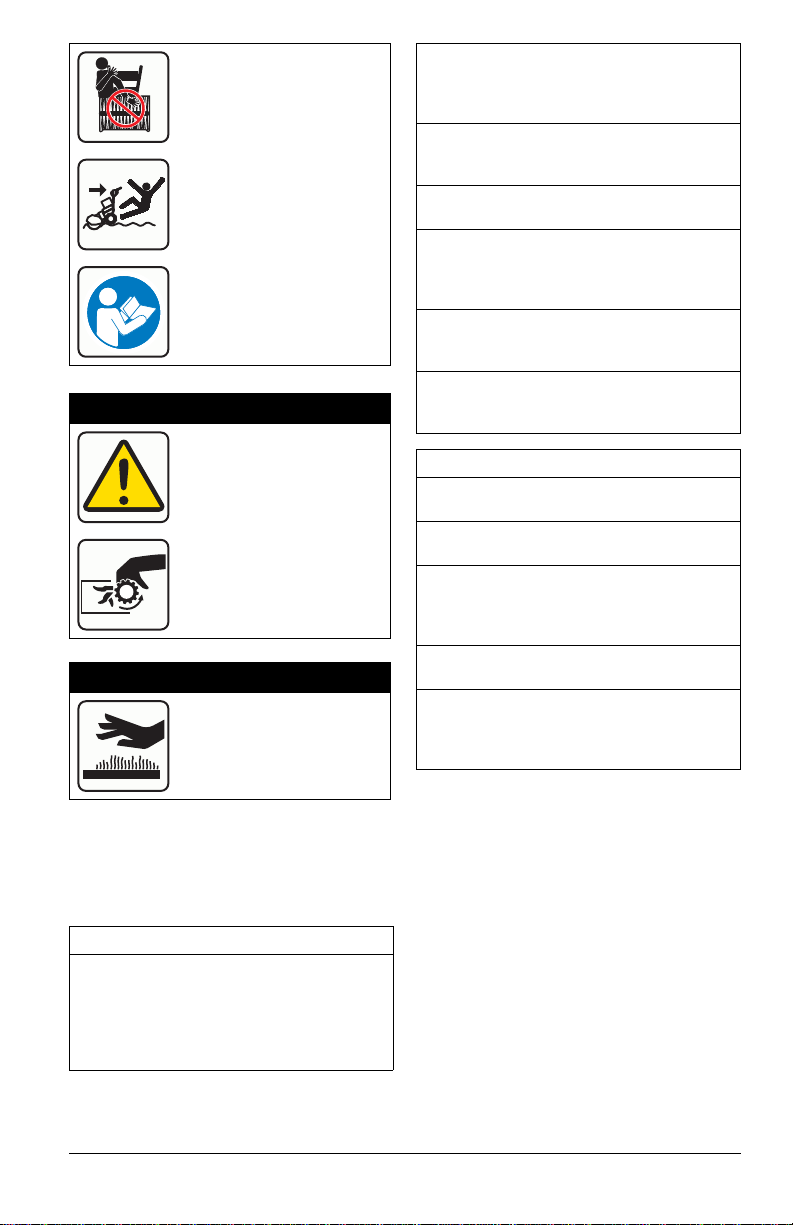
NEVER leave a running unit unattended.
ALWAYS stop engine and remove key
before leaving unit to prevent unauthorized
use.
DO NOT put hands or feet near or under
rotating parts. Keep clear of the discharge
area at all times.
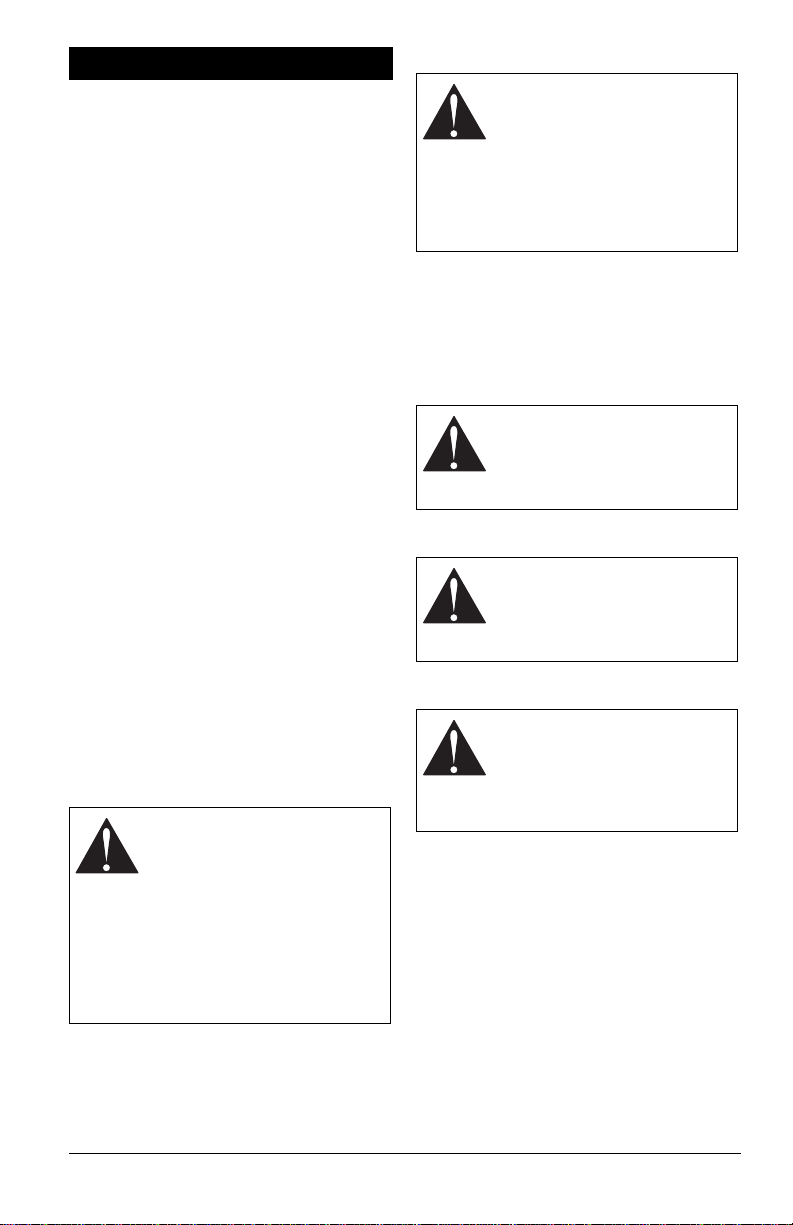
Moving and/or rotating parts can cut off body
parts such as fingers or a hand. NEVER
place your hands, other body part or clothing
near any moving parts while unit is running.
ALWAYS keep hands away from all pinch
points.
DO NOT touch parts which might be hot
from operation. Allow parts to cool before
attempting to maintain, adjust or service.
Thrown objects can cause injury. Check for
weak spots on docks, ramps or floors. Avoid
uneven work areas and rough terrain and
stay alert for hidden hazards.
Exercise extreme caution when operating on
or crossing gravel drives, walks or roads.
Stay alert for hidden hazards or traffic.
After striking a foreign object, stop the
engine, remove the wire from the spark plug,
disconnect the cord on electric motors,
thoroughly inspect the unit for any damage,
and repair the damage before restarting and
operating the unit.
If the unit should start to vibrate abnormally,
stop the engine and check immediately for
the cause. Vibration is generally a warning
of trouble.
Stop the engine whenever you leave the
operating position and when making any
repairs, adjustments or inspections.
When cleaning, repairing or inspecting the
unit, stop the engine and make certain that
all moving parts have stopped. Disconnect
the spark plug wire and keep the wire away
from the plug to prevent someone from
accidentally starting the engine.
DO NOT run the engine indoors, except
when starting the engine and for
transporting the unit in or out of the building.
Open the outside doors; exhaust fumes are
dangerous.
NEVER operate the unit without proper
guards, and other safety protective devices
in place and working.
ALWAYS stand clear of the discharge area
when operating this unit.
NEVER direct the discharge toward people
or areas where injury or property damage
can occur from thrown objects. Keep
children and others away.
DO NOT overload the unit capacity by
attempting to operate at too fast a rate.
NEVER operate the unit at high transport
speeds on slippery surfaces. Look behind
and use care when operating in reverse.
DO NOT operate in reverse unless
absolutely necessary. ALWAYS back up
slowly and look down and behind before and
while backing.
DO NOT carry passengers.

EN - 6
Disengage attachment when not in use and
when traveling from one work area to
another.
Disengage power to the attachment when
unit is transported or not in use.
Use only attachments and accessories
approved by the manufacturer of the unit
(such as wheel weights, counterweights or
cabs).
This product is equipped with an internal
combustion engine. DO NOT use unit on or
near any unimproved, forest-covered or
brush-covered land unless exhaust system
is equipped with a spark arrester meeting
applicable local, state or federal laws. A
spark arrester, if used, must be maintained
in effective working order by operator.
NEVER operate the unit without good
visibility or light. ALWAYS be sure of your
footing, and keep a firm hold on the handles.
Walk; NEVER run.
NEVER operate unit after or during the use
of medication, drugs or alcohol. Safe
operation requires complete and unimpaired
attention at all times.
NEVER allow anyone to operate this unit
when their alertness or coordination is
impaired.
NEVER touch a hot engine or muffler.
Avoid contact with sharp edges; sharp
edges can cut.
Maintenance and Storage
Secure unit so it will not tip over during
maintenance.
Before cleaning, removing obstructions or
making any inspections, repairs, etc.,
disengage clutch(es), stop engine, remove
key, allow moving parts to stop and hot parts
to cool.
Check hardware at frequent intervals for
proper tightness to be sure the unit is in safe
working condition.
Check clutch and brake operation
frequently.
DO NOT change engine governor settings
and DO NOT over-speed engine.
Adjust and service as required. Motion of
drive wheels and attachment must stop
quickly when clutch levers are released.
ALWAYS maintain unit in safe operating
condition. Damaged or worn out muffler can
cause fire or explosion.
Keep unit free of ice or other debris. Clean
up oil or fuel spills.
ALWAYS keep protective structures, guards,
and panels in good repair and secured in
place. NEVER modify or remove safety
devices.
NEVER store the unit with fuel in the fuel
tank inside a building where ignition sources
are present such as hot water heaters,
space heaters or clothes dryers. Close fuel
valve and allow the engine to cool
completely before storing in any enclosure
or covering the unit.
ALWAYS refer to operator's manual for
important details if the unit is to be stored for
an extended period.
Maintain or replace safety and instruction
labels as necessary.
Run the unit a few minutes after removing
snow to prevent freeze-up.
Personal Protection
DO NOT operate the equipment without
wearing adequate clothing. Avoid loose
fitting clothing that can get caught in moving
parts. Wear footwear that will improve
footing on slippery surfaces.
Wear adequate safety gear, including safety
glasses with side shields and protective
gloves.
DO NOT wear loose clothing or jewelry, and
tie back hair that may get caught in rotating
parts.
NEVER attempt to clear obstructions or
clean unit while engine is running. Rotating
attachments can cause serious injury.
Protect eyes, face and head from objects
that may be thrown from unit. Wear
appropriate hearing protection.
ALWAYS wear safety glasses or eye shields
during operation or while performing an
adjustment or repair to protect eyes from
foreign objects that may be thrown from the
unit.
Slope Operation
Exercise extreme caution when operating on
slopes. DO NOT operate on steep slopes.
DO NOT operate across the face of slopes;
go up and down. Keep all movement on
slopes slow and gradual.

EN - 7
Use a slow speed to avoid stops or shifts on
slopes. Avoid starting or stopping on a
slope. DO NOT park unit on a slope unless
absolutely necessary. When parking on a
slope ALWAYS block the wheels.
DO NOT operate near drop-offs, ditches, or
embankments. Unit can suddenly turn over if
a wheel is over the edge of a cliff or ditch, or
if an edge caves in.
Fuel
Remove fuel before separating brush
attachment from frame. Ensure unit is
secure and will not tip during maintenance.
DO NOT run engine in an enclosed area.
ALWAYS provide good ventilation. Fumes
from engine exhaust can cause injury or
death.
Fuel is highly flammable and its vapors are
explosive. Handle with care. Use only an
approved gasoline container with an
appropriately-sized dispensing spout.
No smoking, no sparks, no flames. ALWAYS
allow engine to cool before servicing.
NEVER fill fuel tank when engine is running
or hot from operation.
NEVER fill or drain fuel tank indoors.
Replace fuel cap securely and clean up
spilled fuel.
NEVER fill fuel containers inside a vehicle or
on a truck or trailer bed with a plastic liner.
ALWAYS place containers on the ground
away from your vehicle before filling.
When practical, remove gas-powered
equipment from the truck or trailer and refuel
it on the ground. If this is not possible, then
refuel on a trailer with a portable container,
rather than from a gasoline dispenser
nozzle.
Keep the nozzle in contact with the rim of
the fuel tank or container opening at all
times until fueling is complete. DO NOT use
a nozzle lock-open device.
If fuel is spilled on clothing, change clothing
immediately.
Properly remove fuel before tipping unit to
avoid spills.
Towing/Transporting
ALWAYS stop engine, remove key and close
fuel valve or drain fuel when transporting
unit on a truck or trailer.
Use extra care when loading or unloading
unit onto trailer or truck. Secure unit chassis
to transport vehicle. NEVER secure from
rods or linkages that could be damaged. DO
NOT transport unit while engine is running.
Accessories
Use only Ariens Company-recommended
attachments or accessories that are
designed for your unit and that are
appropriate to your use and can be used
safely in your application.

EN - 8
UNPACK UNIT
Tools Required:
• Tire Gauge
•Pliers
• 13 mm (1/2"), 10 mm (3/8"), 12 mm (7/16")
and 15 mm (9/16") wrench or adjustable
wrench
Unfold Handlebars
See Figure 3.
1. Remove lower handlebar hardware sets
from handlebars.
2. Loosen, but DO NOT remove upper
handlebar hardware.
3. Loosen, but DO NOT remove shift rod
hardware.
4. Place the speed selector lever in the sixth
forward position.
5. Rotate the handlebars into operating
position.
NOTICE: Be careful not to damage cable
spring hooks when rotating handlebars
upward.
See Figure 4.
6. Reinstall lower handlebar hardware and
tighten all handlebar hardware.
7. Make sure shift rod is correctly aligned
and tighten hardware.
ASSEMBLY
WARNING: Read and
understand the Safety section
before proceeding.
WARNING: Dropping or tipping
over boxed unit could result in
personal injury or damage to
unit.
Figure 3
1. Lower Hardware
2. Upper Hardware
3. Shift Rod Hardware
4. Speed Selector Lever
1
3
4
2
Figure 4
1. Shift Rod
2. Hex Bolt
3. Locking Nut
4. Spacer
5. Shift Rod Hardware
1
5
2
4
3

EN - 9
Install Brush Lock Cable
See Figure 5.
1. Remove zip-tie around right handlebar to
release brush lock trigger.
See Figure 6.
2. Guide lock cable through notch in lock
arm bracket.
3. Insert brush lock cable end snap into lock
arm bracket.
Figure 5
Figure 6
1. Lock Cable
2. Cable End Snap
3. Lock Arm Bracket
1
2
3

EN - 10
1. Traction Drive Clutch Lever
2. Attachment Clutch Lever
3. Speed Selector Lever
4. Brush Lock Trigger
5. Brush Guard
6. Brush
7. Caster Wheels & Height Adjustment
8. Fuel Tank and Cap
9. Recoil Starter Handle
10. Choke Control Lever
11. Throttle Control Lever
12. Fuel Valve
13. Engine Switch
14. Electric Start Button
15. Oil Fill / Dipstick
16. Oil Drain
17. Recoil Guard Foam Cover
18. Belt Cover
CONTROLS & FEATURES
13
4
2
10
11
9
16 15
13
6
5
18
8
17
7
12
Figure 7
14

EN - 11
See Figure 7 for all controls and features
locations.
ENGINE SWITCH
See Figure 8.
Controls power to the engine.
FUEL VALVE
See Figure 9.
Controls fuel flow to the engine.
ELECTRIC START BUTTON
Starts a correctly choked engine.
CHOKE CONTROL LEVER
See Figure 10.
Controls airflow to the engine.
THROTTLE CONTROL LEVER
See Figure 11.
Controls engine speed.
SPEED SELECTOR LEVER
See Figure 12.
Controls the speed of forward and reverse
travel.
ATTACHMENT CLUTCH LEVER
(RIGHT SIDE)
See Figure 13.
Controls brush rotation.
WARNING: Read and
understand the Safety section
before proceeding.
Figure 8
Stop Run
Figure 9
Figure 10
Off
On
Figure 11
Run
Idle
Figure 12
Figure 13

EN - 12
TRACTION DRIVE CLUTCH
LEVER (LEFT SIDE)
See Figure 14.
Allows unit to travel forward and in reverse.
BRUSH LOCK TRIGGER
See Figure 15.
Unlocks and locks brush to change cleaning
angle.
DUAL HANDLE INTERLOCK
Allows brush to rotate without holding
attachment clutch lever continuously. Brush
continues to turn until both clutch levers are
released.
IMPORTANT: All references to left, right, front
or rear are given from the perspective of
operator in operator’s position, facing the
direction of forward travel.
EMERGENCY STOPPING
1. Release both clutch levers.
2. Turn engine switch to off position.
3. Wait for all moving parts to stop before
leaving operator’s position.
BEFORE OPERATING UNIT
1. During Winter Operation: Check for
frozen components.
a. Set engine switch to stop position.
b. Engage attachment clutch lever and
pull recoil starter handle.
c. If handle does not pull, move unit to a
warm area to thaw.
2. Check fuel level and add fuel if needed.
IMPORTANT: Use fresh unleaded fuel with
an octane rating of at least 87. DO NOT use
E85 blended fuels; the engine is not E20 /
E30 / E85 compatible. The maximum
recommended ethanol content is 10%.
3. Check engine oil level and add oil if
needed. Refer to engine manual.
4. Check function of controls.
• Attachment Clutch Lever
• Traction Drive Clutch Lever
• Dual Handle Interlock
5. Know how to stop in an emergency. See
Emergency Stopping on page 12.
START THE ENGINE
1. Electric Start Models Only: Connect
power cord to starter and then into 120V
3-wire grounded outlet.
IMPORTANT: Use a power cord that is UL
listed or CSA certified, rated for a minimum of
13 amps, grounded and labeled as suitable
for outdoor use.
All Models
2. Turn fuel valve to on position.
3. Set engine switch to run position.
4. Move choke control lever to on position.
Figure 14
Figure 15
OPERATION
WARNING: AVOID INJURY.
Read and understand the Safety
section before proceeding.

EN - 13
5. Move throttle control lever one-third of the
way toward full-throttle.
6. Electric Start Models Only: Press electric
start button.
NOTICE: DO NOT run starter more than 10
times at intervals of 5 seconds on / 5 seconds
off or overheating and damage may occur.
7. Recoil Start Models Only: Pull recoil
starter handle.
a. Grasp handle and pull rope out slowly
until it pulls harder.
b. Pull handle firmly and quickly with a
rapid, continuous full-arm stroke.
Repeat until engine starts. If engine
does not start, see Troubleshooting
on page 25.
c. Let handle rewind slowly after engine
starts. DO NOT let handle snap
against engine.
8. Gradually turn choke off as engine
warms.
9. Electric Start Models Only: Disconnect
power cord from outlet and then from
starter.
OPERATE UNIT
1. Select desired speed.
2. Engage traction drive clutch.
3. Engage attachment clutch.
NOTICE: Stop brush when traveling between
work areas.
NOTICE: Release both clutch levers before
changing speed.
STOP THE ENGINE
1. Release attachment drive clutch lever.
2. Release traction clutch lever.
3. Move throttle control lever to the idle
position.
4. Turn engine switch to off position.
5. Turn fuel valve to off position.
SET BRUSH HEIGHT
Check Brush Clearing Width
See Figure 16.
1. Move brush to a dusty, flat surface.
2. Start brush at slow speed and run in a
stationary position for 30 seconds.
3. Lift brush head and move unit backward.
4. Stop engine. See Stop the Engine on
page 13.
5. Check width of swept area. Brush pattern
should be 5 – 7.6 cm (2 – 3") wide along
brush length.
• If clearing width is too wide, raise brush.
• If clearing width is too narrow, lower
brush.
Adjust Brush Height
See Figure 17.
Adjust height so brush rests 3 – 6 mm
(1/8 – 1/4”) above delicate surfaces. For hard
surfaces, adjust height so brush lightly
touches surface.
IMPORTANT: Spacers on each caster wheel
must be adjusted equally.
1. Lower brush:
a. Remove lynch pins from caster shaft
tops.
b. Turn desired amount of height
adjuster clips to be removed so they
align with flat side of caster shaftsand
remove clips.
c. Install spacers onto caster shaft tops
and reinstall lynch pins.
2. Raise brush:
a. Remove lynch pins from caster shaft
tops.
b. Remove desired amount of height
adjuster clips from caster shaft tops
and install onto lower caster shaft
ends.
c. Turn height adjuster clips so they DO
NOT align with flat side of caster
shafts.
d. Reinstall lynch pins.
CAUTION: AVOID INJURY. If
brush height is too low, brush
can drive machine rearward
when attachment clutch is
engaged.
Figure 16

EN - 14
SET BRUSH ANGLE
See Figure 18.
1. Squeeze brush lock trigger to unlock
brush position.
2. Move handlebars left or right until brush is
in desired position.
3. Release trigger to lock brush position.
TRANSPORT UNIT
1. Stop engine and close fuel valve.
2. Secure unit chassis to transport vehicle.
NOTICE: NEVER secure from rods or
linkages that could be damaged.
For Best Sweeping Results
• Run in an overlapping series of paths.
• Start in the middle of large areas and
sweep debris to each side.
• ALWAYS direct discharge with wind
direction.
• Snow is most easily removed as soon as
snow falls.
For Best De-Thatching Results
IMPORTANT: Front caster kit is required for
de-thatching. See Accessories on page 24.
• De-thatch in spring to clear winter
undergrowth.
• Adjust brush height so it just touches the
grass.
• Set brush angle full left or right so thatch
gets cleared only once.
• De-thatch dry grass.
• Use a slow speed to clear thatch to avoid
damage to lawn.
Figure 17
1. Lynch Pin
2. Caster Shaft
3. Height Adjuster Clip
1
2
3
Figure 18

EN - 15
Your Ariens dealer can provide service and
adjustments to keep your unit operating at
peak efficiency. Contact an authorized engine
manufacturer’s service center for engine
service.
SERVICE POSITION
IMPORTANT: DO NOT tip unit onto brush.
Remove brush attachment if maintenance
requires tipping unit forward. Ensure unit is
secure and will not tip.
Place Unit in Service Position
1. Move unit to a flat, level surface.
2. Stop engine and allow moving parts to
stop and hot parts to cool.
3. Loosen, but DO NOT remove hardware
securing belt cover and remove belt
cover.
See Figure 19.
4. Remove hardware securing belt finger
and remove belt finger.
5. Remove attachment drive belt from
attachment sheave.
See Figure 20.
6. Disconnect brush lock cable from J-clamp
on engine mount.
MAINTENANCE
WARNING: Read and
understand the Safety section
before proceeding.
Figure 19
1. Belt Finger
2. Hex Bolt
3. Locking Washer
4. Flat Steel Washer
5. Attachment Drive Belt
6. Attachment Sheave
1
2
43
6
5
Figure 20
1. J-Clamp
2. Brush Lock Cable
1
2

EN - 16
See Figure 21.
7. Remove hardware securing brush lock
trigger to handlebar and allow trigger to
rest on brush attachment.
IMPORTANT: Support tractor / frame so it will
not tip when disconnected from brush
attachment in next step.
See Figure 22.
8. Remove hardware securing brush
attachment to tractor / frame.
9. Rotate brush attachment apart from
tractor / frame on mount rod and remove
from frame.
See Figure 23.
10. Slowly rotate tractor / frame forward so it
rests on attachment sheave. Protect
attachment sheave so it does not incur
damage.
11. Remove hardware securing bottom cover
and remove bottom cover.
WARNING: ALWAYS support
unit frame and brush attachment
when loosening hardware
holding them together.
Figure 21
1
1. Machine Screw
2. Lock Washer
3. Brush Lock Trigger
2
3
WARNING: AVOID INJURY.
Before rotating unit, close fuel
valve and drain fuel from tank
and fuel system. (Refer to
engine manual for instructions.)
Make sure unit is secure and will
not tip.
CAUTION: AVOID ENGINE
DAMAGE. Do not leave unit in
service position for longer than
30 minutes. Allow 30 minutes for
oil to return to crankcase before
starting engine.
Figure 22
1. Tapping Screw
2. Mount Rod
3. Mount Bracket
1
2
3

EN - 17
RETURN UNIT TO OPERATING
POSITION
1. Reinstall bottom cover and secure with
six tapping screws.
2. Return tractor / frame to operating
position and onto a support.
3. Lift brush attachment rear and lower into
frame so mount brackets rest on mount
rod.
4. Secure brush attachment to frame with
four tapping screws, but DO NOT tighten
hardware.
5. Reinstall attachment belt onto attachment
sheave.
6. Reinstall belt finger and secure with two
flat steel washers, two locking washers
and two hex bolts. Tighten hardware.
7. Torque hardware installed in step 4 to
22.8 – 34.1 N•m (16.8 – 25.2 lb-ft).
8. Check belt finger clearance:
• Engage attachment clutch lever and
make sure belt finger located opposite
belt idler is less than 3.2 mm (1/8") from
belt, but not touching the belt. See
Figure 24.
• If needed, adjust clearance by
loosening hex bolts, repositioning belt
finger, and tightening bolts.
9. Reinstall belt cover and tighten hardware.
10. Reinstall brush lock trigger onto
handlebars and route brush lock cable
through J-clamp on engine mount.
11. Adjust attachment clutch / brake. See
Adjust Attachment Clutch & Brake on
page 21.
12. Reconnect spark plug wire and fill fuel
tank.
IMPORTANT: Check all adjustments after
first use.
Figure 23
1. Bottom Cover
2. Engine Sheave
3. Engine
1
2
3
CAUTION: AVOID ENGINE
DAMAGE. Allow unit to rest in
operating position for 30 minutes
before starting engine.
3.2 mm (1/8")
Figure 24

EN - 18
MAINTENANCE SCHEDULE
SERVICE PARTS
See your Ariens dealer to purchase service
parts for your unit.
CHECK DUAL HANDLE
INTERLOCK
1. Stop engine.
2. Engage traction drive clutch and then the
attachment drive clutch.
3. Release the attachment clutch lever. The
attachment clutch should stay engaged
until the traction drive clutch lever is
released.
CHECK FASTENERS
Check for loose hardware.
CHECK CLUTCH CABLE
ADJUSTMENTS
Brush must stop within 5 seconds when
attachment clutch lever is released.
Wheels must stop quickly when traction drive
clutch lever is released.
If clutches do not engage or disengage
correctly, see Adjust Attachment Clutch &
Brake on page 21 or See Adjust Traction
Drive Clutch on page 23.
CHECK TIRE PRESSURE
Keep tires inflated to pressure listed on tire
sidewall.
CHECK ENGINE OIL
NOTICE: Engine oil level must be maintained
at correct level or engine damage may occur.
Refer to engine manual.
CHANGE ENGINE OIL
Refer to engine manual.
CLEAN RECOIL GUARD FOAM
COVER
The recoil guard foam cover must be kept
clean and free of snow and debris.
If cover becomes clogged, remove and gently
vacuum or wash with warm water.
IMPORTANT: Cover MUST be installed when
using unit in winter conditions. The cover
prevents snow from entering the recoil guard
and freezing the recoil pawls. Cover is not
necessary for operation during non-winter
months.
IMPORTANT: If cover is clogged with snow,
remove it and allow foam to thaw or rinse with
warm water. Allow cover to dry before
reinstalling.
Service Performed
Each Use
Every 5 hrs.
Every 25 hrs.
Annually
Check Clutch Lever
Operation •
Check Dual Handle
Interlock •
Check Fasteners •
Clean Recoil Guard Foam
Cover •
Check Engine Oil •
Check Clutch Cable
Adjustments * •
Check Tire Pressure •
Change Engine Oil **
General Lubrication • •
* After first use.
** Refer to engine manual for instructions.
Description Part No.
Ariens Hi-Temp Grease
• 3 oz. cartridges (3)
• 14 oz. cartridge (1) 00036800
00036700
Fuel Stabilizer (4 oz.) 04730400
04742500 (for
Canada Only)
Spark Plug 21530400
Ariens 5W-30 Engine Oil
• 16 oz. 00091000
• 32 oz. 00067600
WARNING: AVOID INJURY.
Explosive separation of tire and
rim parts is possible.
• DO NOT inflate tires above
the recommended pressure.
• DO NOT inflate tires with a
compressor; use a hand
pump.
• DO NOT stand in front of tire
assembly when inflating. Use
a clip-on chuck and extension
hose long enough to allow you
to stand to one side.
• DO NOT mount a tire without
proper equipment and
experience.
This manual suits for next models
1
Table of contents
Other Ariens Blower manuals