Arista AP-3500-E01 User manual

This manual is a user guide for AP-3500-E01 Oce Thin Client. It includes
detailed description about how to install and operate the product. Arista
Corporation recommends users to read through the entire manual and
follow instructions to avoid any kind of obscurity in using the product.
For any questions or support, please call us at 1.877.827.4782 Monday
through Friday 8:00am to 5:00PM Pacic Time.
Publication date: 2016/10/25
Version No.: V2.2
AP-3500-E01 Oce Thin Client
USER MANUAL
Talk to us. We listen.

2
Product safety precautions
Important: Read all the contents of this instruction manual carefully before
using the AP-3500-E01 Oce Thin Client.
It is recommended to follow the instructions and safety precautions listed below. This
manual should be saved for future references and use.
• Relative humidity: 25%~80%
• Storage temperature: -20oC to 60oC(-4F to 140F)
• Operation temperature: 0~50oC(32F to 122F)
• Unplug the unit when not in use for an extended period of time.
• Consult a service technician if the unit does not operate normally when you have
followed the instructions in this manual.
• Do not attempt to repair this product yourself. Always get a qualified service
technician to carry out adjustments or repairs.
• Do not place heavy objects on the unit.
• Always use the power cord supplied with this unit. For any reason a different
powercordhastobeusedwiththisunit,itshouldbecertiedbylocalandnational
standards and used under guidance of authorized technician.
• Never use a faulty power cord with this unit. Please contact the manufacturer or
nearest authorized repair service right away for a replacement if damaged power
cord is received.
• The power supply cord is used as the main disconnect device. Ensure that the socket
outlet is easily accessible after installation.
• Overloaded AC outlets, extension cords, frayed power cords, and broken plugs are
extremelydangerous.Theymay,andcan,resultinanelectricalshockorrehazard.
Call an authorized service technician for any replacements.
• Hands must be dry when plugging the power cord into an AC outlet to prevent
electrical shock. Do not damage the power cord by disassembling, bending, pulling
orexposingittoheatasitmaycauseareorelectricalshock.
• Make sure to completely insert the power plug into an AC outlet. Insecure
connectionscancauseare.
• Ensure that the power source is grounded correctly.
• Unplug the unit if cleaning is needed. The unit may be wiped down with a dry or
slightlydampclothwhenthepoweriso.

3
Contents
Product safety precautions ................................................................................................2
Contents...............................................................................................................................3
Chapter 1 Welcome .........................................................................................................4
Features..........................................................................................................................4
Product specications..................................................................................................5
Unpacking ......................................................................................................................6
Chapter 2 Basics.................................................................................................................7
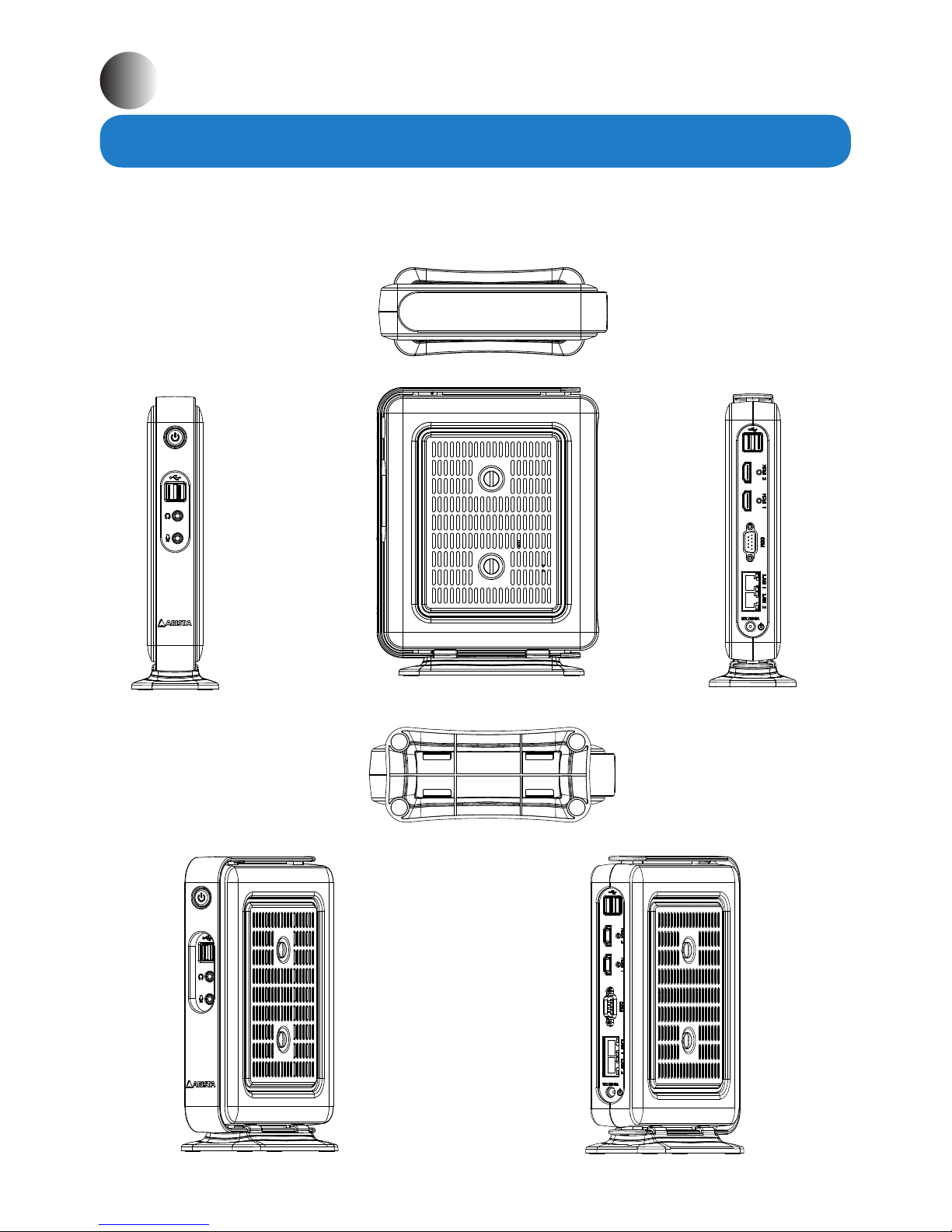
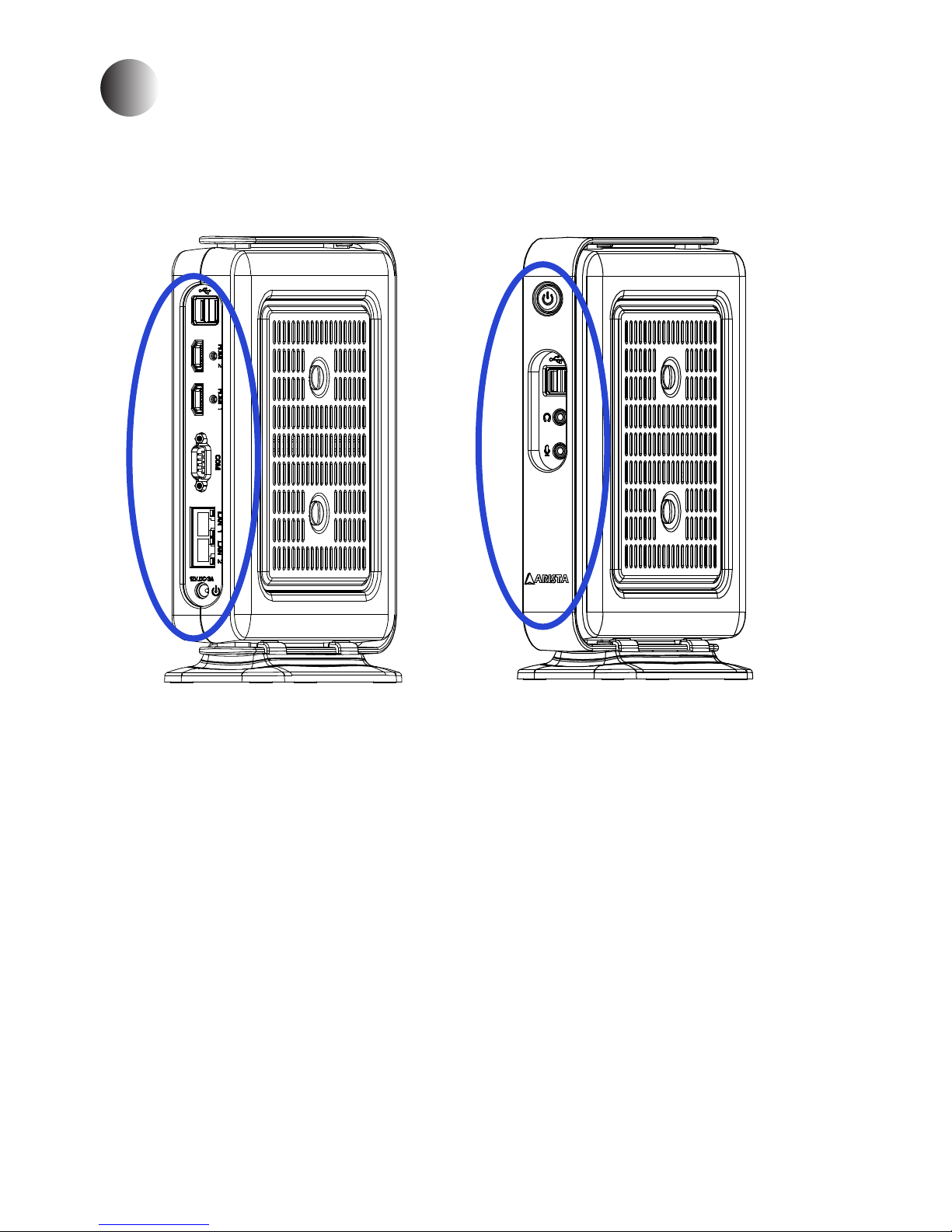
Product overview.......................................................................................................7
Physical dimensions ....................................................................................................9
Chapter 3 Connections ...................................................................................................10
Pins in the Serial port (COM1)...................................................................................11
Mounting the Thin Client............................................................................................12
Connecting to a display............................................................................................15
Connecting to keyboard or mouse..............................................................................15
Connecting to network............................................................................................16
Connecting earphones or speaker..............................................................................16
Connecting the power supply.............................................................................17
Installing memory module/expansion card..........................................................18
Clearing CMOS data....................................................................................................22
Chapter 4 BIOS Setup.......................................................................................................23
Introduction....................................................................................................23
Entering the setup..............................................................................................24
Main Menu..........................................................................................26
Advanced Menu............................................................................................27
Chipset Menu....................................................................................33
Security Menu................................................................................................37
Boot Menu................................................................................................38
Save&Exit Menu.........................................................................................39
Chapter 5 Appendix.........................................................................................................40
Care and Maintenance ...............................................................................................40
Product Limited Warranty..........................................................................................41
Disposal and Recycling Information.....................................................................46
Disclaimer and Copyright Notice..............................................................................46
Contents

4
Features
• Intel E3845 1.91GHz ATOM CPU
• Up to 8GB DDR3 SO-DIMM Memory
• Dual Gigabit LAN
• SATA DOM for Storage Option
• Mini PCIe Expansion Slot
• ACP Enabled, PXE Boot
• Desktop or VESA Mount Available
Arista AP-3500-E01 thin client is a lightweight computer that is purpose-built for remote
access to a server (typically cloud or desktop virtualization environments). Thin clients
occur as components of a broader computing infrastructure, where many clients share
their computations with a server or server farm. The server-side infrastructure makes use
of cloud computing software such as application virtualization, hosted shared desktop
(HSD) or desktop virtualization (VDI). This combination form is known as cloud based
system,wheredesktopresourcesarecentralizedintooneormoredatacenters.Benets
of centralized access are optimization of hardware resources, reduced maintenance and
more security.

5
Product specications
System
CPU Intel E3845 1.91GHz ATOM CPU
Chipset (By CPU)
Memory Up to 8GB DDR3 SO-DIMM
Video controller Intel Gen7 Intel Graphics DX 11, OGL3.2
Video interface Dual HDMI
Storage option SATA DOM, 2.5" HDD, 2.5" SSD
Compactash N/A
Keyboard/Mouse USB
Audio Mic In, Line Out
Watchdog Timer N/A
Remote Boot ACP, PXE
Expansion Slot Mini PCIe x 1, CFast card connector x1
I/O Communication
USB port 1 x USB 3.0, 3 x USB 2.0
Serial port 1 x RS-232/422/485
IEEE 1394 N/A
LAN 2 x Gigabit
Parallel N/A
Power button 1 x Power button
Power 1x DC-IN power(12V, 1.05A)
Operating system
OS Support Windows 7 & up
Power / Thermal Specs.
Power requirement ( Max ) 12VDC/1.05A
Power consumption 13W
Recommended power
supply
18W
Heat dissipation 43 BTU/hr
Physical information
Mounting
Desktop, VESA Mount option
Net Weight 2.75Lbs / 1.2 Kg
Physical Dimension
(W x H x D)
2.80 x 9.30 x 7.17 inch
70.5 x 236.5 x 182.0 mm
Environmental information
Operating temperature 0~35°C (32~95°F)
Storage temperature -20~60OC [-4~140F]
Relative humidity 10% to 95% (non-condensing)
IP/NEMA Rating N/A
Certication FCC, CE, UL 60950-1

6
AP-3500-E01 Thin Client x1 AC/DC power adapter x1 AC power cable x1
Unpacking
AC/DC power adapter x1
AC power cable x1
Ordering Information
Options AP-3500-E01-003 AP-3500-E01-P03
CPU E3845 ATOM CPU E3845 ATOM CPU
Memory 4GB DDR 4GB DDR
Storage N/A N/A
Remote Boot ACP Enabled PXE
Power Supply 110/220VAC Input 110/220VAC Input
Operating System N/A N/A
The unit is shipped with items listed below, inspect them carefully to make sure there is no
damage and all the items are available with your shipment.

7
Product overview
Chapter 2 Basics
Side
Side
Bottom
Top
Front
AP-3500-E01 Oce Thin Client

8
Speed LED Activity LED
LED Indications on the LAN port
Status Description
Activity
LED
O No network connection
On Data transmission activity
Speed
LED
O Data transmission at the rate of 10Mbps
Orange Data transmission at the rate of 1Gbps
Green Data transmission at the rate of 100Mbps
1
2
3
4
5
6
7
8
9
10
1. Power button 6. 2 x HDMI ports
2. 2 x USB ports 7. COM port
3. Earphone/Headphone jack 8. 2 x RJ45 LAN ports
4. Microphone jack 9. DC 12V/3A power jack
5. 2 x USB ports 10. Desktop stand base(removable)

9
ThediagramsbelowshowthephysicalandspecicdimensionsoftheAP-3500-E01Thin
Client.
Physical dimension
222.0mm
8.74"
236.5mm
9.31"
152.2mm
5.99"
32.0mm
1.26"
182.0mm
7.17"
70.5mm
2.77"
AP-3500-E01 Oce Thin Client
44.6mm
1.76"

10
Connectors are located on the side of AP-3500-E01 Thin Client.
Chapter 3 Connections
This section describes the connections/connectors available on the AP-3500-E01OceThin
Client.

11
Pins in the serial port (COM1)
6789
1 2 3 4 5
Pin NO. Denition(RS-232 mode) Denition(RS-422/RS-485 mode)
1 DCD, data carrier detect TX-, Transmit data ground (RS-422/RS-485)
2 RXD, Receive data TX+, Transmit data(RS-422/RS-485)
3TXD, Transmit data RX+, Receive data (RS-422)
4 DTR, Data terminal ready RX-, Receive data ground (RS-422)
5 GND, Signal ground GND, Signal ground
6 DSR, Data set ready N.C.
7 RTS, Request to send N.C
8 CTS, Clear to send N.C
9 Ring-IN, Ring indicator N.C.
Note: COM1 port is available for RS-232/RS-422/RS-485 Mode.

12
Desktop Stand base
Mounting clip
Mounting the Thin Client
Desktop mounting
The AP-3500-E01 Office Thin Client can be directly placed on a shelf or table by using
desktop stand base(supplied with the unit).
Please follow the steps shown in the diagram below:
Step1. Place the bottom side ofAP-3500-E01 OceThin Client within the place on the
desktop stand base where there are four mounting clips.
Step2. SlidetheDesktopstandbasealongwiththeAP-3500-E01OceThinClientbottom
sideuntilthefourmountingclipsonthestandbasermlylocktheunit.

13
Mounting
screw
Display back panel
VESA
bracket
VESA mounting
You can also mount the AP-3500-E01OceThinClient onto a display. For display mount,
VESA mounting brackets and screws are available (sold separately).
Please follow the steps shown in the diagram below:
Step1. Asshowninthegurebelow,ndthefourscrewholespredrilledatthebackofthe
display.
Screw holes
Step2. Align the four mounting screw holes on the AP-3500-E01 VESA bracket with the
screw holes on the display.Tighten the four screws with a screw driver to x the VESA
bracket onto the display.

14
Spring hook
Spring hook
Step3. If the AP-3500-E01OceThinClient is desktop mounted, please slide the desktop
stand base out to remove it from the unit.
Step4. Snag the white bottom base of the AP-3500-E01 OceThin Client with the two
Spring hooks on the VESA bracket installed on the display. Make sure the AP-3500-E01
OceThinClientiscorrectlyandsecurelyseatedontothedisplay.

15
Connecting to a display
AP-3500-E01
AP-3500-E01
HDMI port
Display
HDMI port
HDMI cable(not supplied)
• ConnectoneendoftheHDMIcabletotheHDMIportoftheAP-3500-E01OceThin
Client. Connect the other end of the HDMI cable to the HDMI port of a display.
Connecting to a display through HDMI port
Mouse
Keyboard
USB port
Connecting to keyboard and mouse
•InsertaUSBkeyboardandaUSBmouse(not supplied) to AP-3500-E01OceThinClient
for controlling on the computer.

16
Modem
Connecting to network
Connecting earphones or speaker
• ConnectoneendoftheRJ45LANcabletotheLANportoftheAP-3500-E01Oce
Thin Client. Connect the other end of the RJ45 LAN cable to the LAN port of a modem.
• Connect the earphone end of the audio cable to the Earphone jack of the AP-3500-E01
OceThinClient.ConnectthemicrophoneendoftheaudiocabletotheMicrophone
jack of the AP-3500-E01 Office Thin Client. Also, you can connect to a speaker by
connectingtotheEarphonejackoftheAP-3500-E01OceThinClient.
LAN port
3.5mm audio cable(not supplied)
earphone/headpone
Speaker
LAN port
RJ45 LAN cable(not supplied)
AP-3500-E01
AP-3500-E01

17
DC power connector AC outlet
AP-3500-E01
• Connect one end of the 12V AC/DC power adapter to the DC-in(12V) power connector
of the AP-3500-E01 Office Thin Client. Connect the other end of 12V AC/DC power
adapter to an AC outlet.
Connecting the power supply
Follow the steps below to connect the power supply.

18
Installing memory module/expansion card
Before you install the memory module or expansion card, please follow the instructions
below to open the bottom cover of theAP-3500-E01OceThinClient.
1. Asshowninthegurebelow,remove the two screws at the center of the bottom cover.
2. Then remove the bottom cover of the AP-3500-E01 Office Thin Client and a metal
protectionbase,youwillndtheDDR3SO-DIMMslot,MINI_PCIEslotandCFastcard
slot on the motherboard.
TheAP-3500-E01OceThinClientcomeswiththeB048motherboard,andtheDDR3SO-
DIMM slot, MINI-PCIE slot and CFast card slot all are built on the motherboard.
The B048 motherboard provides one SO-DIMM slot for DDR3 1333MHz SDRAM memory
modules and supports memory size up to 8GB.
The DIMM1 slot is intended for a memory module.
You may install 64 MB, 128 MB, 256
MB, 512 MB, 1GB, 2GB, 4GB and 8GB DDR DIMM
into the SO-DIMM slot.
Note: Make sure to unplug the power supply before adding or removing DIMM or other
system components. Failure to do so may cause severe damage to both the motherboard
and the components.
Installing the DIMM

19
Follow the steps outlined below to install the SO-DIMM.
1. Locate the DIMM on the SO-DIMM slot and align the notch on the DIMM with the key on
the slot.
Note: DO NOT force a DIMM into a slot to avoid damaging the DIMM.
2. Insert the DIMM into the slot at 45-degree angle, then pushitinuntilthegoldennger
on the DIMM is deeply inserted into the DIMM slot.
3. Firmly press the DIMM down to lock the module in place.
Follow these steps to remove the DIMM.
1.Useyourngertosimplypushawaytheretainingclipsonbothsidesofthe
DIMM
slot outward to unlock the DIMM.
Removing the memory module
The notch on
the DIMM
DIMM
Goldenngeron
the DIMM
The key on
the slot

20
Installing CFast card
Removable memory storage is available on computer with Arista B048 motherboard.
The storage is in the form of a CFast memory card( a compact SATA SSD that comply
with CFast. CFast card slot supports CFast TypeI/II card. Orient the CFast card so that
the notch on the card aligns with the key on the slot(See Figure1 and Figure2).
CFast card slot
CFast card
Figure1 Figure2
2. Then, the retaining clip will release, and gently remove the DIMM from the
module.
Note: Make sure to unplug the power supply before adding or removing DIMM
or other
system components. Failure to do so may cause severe damage to both
motherboard and
the components.
Table of contents
Other Arista Desktop manuals