manuals.online logo
Brands
  1. Home
  2. •
  3. Brands
  4. •
  5. SilverStone
  6. •
  7. Desktop
  8. •
  9. SilverStone LCD 13 User manual

SilverStone LCD 13 User manual

Other SilverStone Desktop manuals

SilverStone GD04 Grandia Series Assembly instructions

SilverStone

SilverStone GD04 Grandia Series Assembly instructions

SilverStone Grandia GD01 Series User manual

SilverStone

SilverStone Grandia GD01 Series User manual

SilverStone SST-LC20M User manual

SilverStone

SilverStone SST-LC20M User manual

SilverStone RVZ03 Reference manual

SilverStone

SilverStone RVZ03 Reference manual

SilverStone Fortress SFTZ01-E User manual

SilverStone

SilverStone Fortress SFTZ01-E User manual

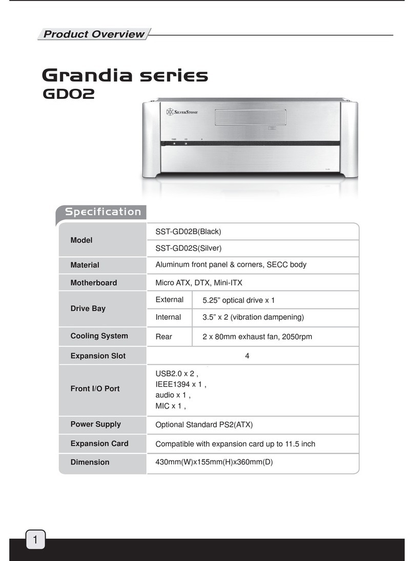
SilverStone SST-GD02B Grandia Sereis GD02 Operating and safety instructions

SilverStone

SilverStone SST-GD02B Grandia Sereis GD02 Operating and safety instructions

Popular Desktop manuals by other brands

StarTech.com ARMSTSL manual

StarTech.com

StarTech.com ARMSTSL manual

Dell Inspiron 5720 quick start guide

Dell

Dell Inspiron 5720 quick start guide

GÜDE WERKBANK GW 6/2 XL Translation of the original instructions

GÜDE

GÜDE WERKBANK GW 6/2 XL Translation of the original instructions

Lenovo ThinkCentre M62z Vodič za uporabnika

Lenovo

Lenovo ThinkCentre M62z Vodič za uporabnika

Lenovo ThinkCentre M71z user guide

Lenovo

Lenovo ThinkCentre M71z user guide

Fujitsu ESPRIMO C7xx operating manual

Fujitsu

Fujitsu ESPRIMO C7xx operating manual

Bosch DCU 130 operating instructions

Bosch

Bosch DCU 130 operating instructions

Zotac VR GO quick start guide

Zotac

Zotac VR GO quick start guide

HP 260 G2 DM Product End-of-Life Disassembly Instructions

HP

HP 260 G2 DM Product End-of-Life Disassembly Instructions

Sony VAIO VGC-LS21 Specifications

Sony

Sony VAIO VGC-LS21 Specifications

HP ProOne 400 G1 specification

HP

HP ProOne 400 G1 specification

IBM PS/2 60 Hardware maintenance service

IBM

IBM PS/2 60 Hardware maintenance service

Acer Aspire SA60 Service guide

Acer

Acer Aspire SA60 Service guide

Lenovo ThinkCentre M71z Uživatelská příručka

Lenovo

Lenovo ThinkCentre M71z Uživatelská příručka

IBM Aptiva 2198 reference guide

IBM

IBM Aptiva 2198 reference guide

Sony PCV-LX810 - Vaio Slimtop Computer System reference manual

Sony

Sony PCV-LX810 - Vaio Slimtop Computer System reference manual

Dell Precision U3525 Quick reference guide

Dell

Dell Precision U3525 Quick reference guide

MicroTouch IC-215P-AW2 user guide

MicroTouch

MicroTouch IC-215P-AW2 user guide

manuals.online logo
manuals.online logoBrands
  • About & Mission
  • Contact us
  • Privacy Policy
  • Terms and Conditions

Copyright 2025 Manuals.Online. All Rights Reserved.

Disassemble Chart
Product Overview
Specification:
NO:11400110
SST-LC13
Material: Aluminum front panel, 1.0mm SECC body
Color: Black & Silver
Motherboard: Extended ATX*, ATX, Micro ATX
Drive Bay: External - 5.25" x 2 / 3.5" x 2
Internal - 3.5" x 2
Cooling System: Front - 92mm intake, 2100rpm, 21dBA
Rear - 2 x 60mm exhaust, 3000rpm, 25dBA
Expansion Slot: 7
Front I/O Port: USB2.0 x 2, IEEE1394 x 1, audio x 1, MIC x 1
Power Supply: Optional standard PS2 (ATX)
Net Weight: 9 kg
Dimension: 430 mm (W) x 163 mm (H) x 430 mm (D)
February , 2005
e
cification:
S
T-L
C
1
3
Ma
t
e
ri
a
l:
Aluminum front
pan
el,
1.0mm SECC bod
y
EC
b
Color: Black & Silver
3.5 BAY * 2
3.5 BAY * 1(HIDDEN)
STANDARD ATX M/B
9225 FAN
FRONT IO (USB * 2+1394 + AUDIO)
POWER SW
DOOR
5.25 BAY * 2
5.25 BAY * 2
PS2 POWER SUPPLY
6025 FAN* 2
TOP PANEL
3.5 BAY * 1 ( HIDDEN )
LC13
* LC13 has mounting holes for extended ATX motherboards, but it does not fully support all available extended ATX motherboards
on the market. The use of extended ATX motherboard will also require the removal of 3.5" drive bay
ation
1. Unscrew four case screws to remove case
cover
13. Line up optical drive with the front panel
and secure it with screws
19. Use included 3pin to 4pin adapter to
connect a case fan if your motherboard
does not support enough 3pin fan headers
20. After installing all other system components,
place the case cover back onto the case
and secure with screws to complete installation
14. After optical drives are installed, place
the 3.5" drive bracket back into the case
and secure with screws
15. Asecond 3.5" drive bracket is located
beneath the 5.25" drive bays with room for
one more hard drive. It can be taken out
of the case easily with a screw removed
16. After installing hard drive into the bracket,
slide it back underneath the 5.25" drive bays 17. Secure reinstalled bracket with screw 18. For extra EMI protection, route front panel
cables through the included wire ring
7. Remove front 3.5" drive bay covers as
needed depending on how many external
3.5" drive bay device is required
8. Use #6-32 x 6 screws to install hard
drive into the 3.5" drive bracket 9. Install floppy drive or other 3.5" drive bay
device into the drive bracket. Use the
drive bay cover as a guide for lining up
the drive or installed device
10. If one of the external 3.5" drive bay isn't
used, the extra space can be used for
an additional hard drive
11. Optical drive installation- Remove screws
holding the 5.25" drive bay cover 12. Insert optical drive into the 5.25" drive bay
from the front of the case
2. Check for included accessories (screw bag,
3pin to 4pin adapater, and EMI wire ring) 3. Power Supply Installation- Insert power
supply into the case, secure with four
#6-32 x 6 screws
6. Hard Drive and 3.5" bay Installation-
Remove 3.5" drive bracket from the case
5. Place motherboard into the case and
secure with screws
4. Motherboard Installation- Insert included
motherboard standoffs into holes on the
bottom of the case that will lineup with
your motherboard