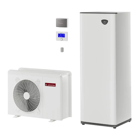
Ariston COMPACT M NET R32 Owner's manual

3301721
3301722
3301723
3301724
420000590201
COMPACT M NET R32
TECHNICAL INSTRUCTIONS FOR INSTALLATION AND MAINTENANCE
EN

2 / EN
Introduction
Dear Madam,
Dear Sir,
thank you for choosing the COMPACT M NET R32 ARISTON
system.
This manual was drawn up with the aim of informing you on
how to install, use and maintain the COMPACT M NET R32 sys-
tem, in order to enable you to optimally use all the functions.
Store this booklet, as it contains all the necessary information
regarding the product following its initial installation.
To find your nearest Technical Assistance Service, please see
our Internet website www.Ariston.com.
Please also refer to the Warranty Certificate that you will find
inside the packaging, or which was handed to you by the in-
staller.
Symbols used throughout this manual
and their meaning
i
WARNING Indicates important information
and particularly delicate operations.
a
WARNING: DANGER Indicates actions that,
if not performed correctly, can lead to gener-
al injuries or malfunctions or material dam-
ages to the appliance; they therefore require
special attention and adequate training.
Warranty
The ARISTON product is covered by a conventional warranty,
which takes effect from the date of purchase of the appliance.
For the warranty conditions, refer to the warranty certificate ac-
companying the product.
Compliance
The CE marking applied to the appliance certifies that it con-
forms with the essential requirements of the following Europe-
an Directives:
–2014/30/EU Electromagnetic Compatibility Directive
–2014/35/EU Low Voltage Directive
–RoHS 3 2015/863/EU on restrictions regarding the use
of certain hazardous substances in electrical and elec-
tronic appliances (EN 50581)
–Regulation (UE) no. 813/2013 relative to ecodesign (no.
2014/C 207/02 - transitional methods of measurement
and calculation)
–2014/68/EU PED
Disposal
PRODUCT CONFORMING TO EU DIREC-
TIVE 2012/19/EU and to Italian Legisla-
tive Decree 49/2014 pursuant to Art. 26
of Legislative Decree no. 49 of 14 March
2014, “Implementation of Directive
2012/19/UE on waste of electrical and
electronic equipment (WEEE)”.
The barred wheeled bin symbol appearing on the appliance or
on its packaging indicates that the product must be collected
separately from other waste at the end of its useful life.
The user must therefore deliver the decommissioned product
to an appropriate local facility for separate collection of electro-
technical and electronic waste. Alternatively, the appliance to
be scrapped can be delivered to the dealer when purchasing a
new equivalent appliance.
Proper separated collection of the decommissioned appliance
for its subsequent recycling, treatment and eco-compatible
disposal helps to prevent negative effects on the environment
and human health, besides encouraging reuse and/or recy-
cling of its constituent materials.

3 / EN
Contents
1. Safety advices
1.1 General warnings and safety instructions 4
1.2 Use of the R32 refrigerant 5
1.3 Symbols affixed to the appliance 6
2. Description of the system
2.1 Outdoor unit 8
2.1.1 Structure 8
2.1.2 Dimensions and weights 9
2.1.3 Hydraulic fittings 10
2.1.4 Accessories 10
2.2 Indoor unit 11
2.2.1 Structure 11
2.2.2 Dimensions and weights 13
2.2.3 Hydraulic fittings 13
2.3 Operational limits 15
2.3.1 Compressor frequency table 15
2.4 Identification 15
2.5 System interface SENSYS HD 16
2.5.1 Description 16
2.5.2 Technical data 17
2.6 Outdoor Sensor 17
3. Installation
3.1 Preliminary warnings 18
3.2 Receiving the product 19
3.3 Installing the outdoor unit 19
3.3.1 Place of installation 19
3.3.2 Noise level 20
3.3.3 Handling 20
3.3.4 Installation 21
3.3.5 Arranging the connections 22
3.3.6 Installing the accessory kit 22
3.4 Installing the indoor unit 23
3.4.1 Place of installation 23
3.4.2 Handling 24
4. Hydraulic connections
4.1 Indoor unit hydraulic connections 25
4.1.1 Safety valve drain 26
4.1.2 Minimum water content 26
4.1.3 Expansion vessel 26
4.1.4 Rated and minimum flow rate 26
4.1.5 Available pressure 27
4.1.6 Characteristics of the supply water 28
4.1.7 Filling the system 28
4.2 Schematic hydraulic diagram 29
5. Electrical connections
5.1 Outdoor unit electrical connections 33
5.2 Indoor unit electrical connections 35
5.3 Example of electrical connection between
indoor and outdoor units 38
5.4 Outdoor unit overview 39
5.5 Indoor unit overview 44
5.6 Installing the system interface 45
5.6.1 Wall installation 45
5.6.2 On-board installation 45
5.7 Installing the Light Gateway 47
6. Commissioning
6.1 Checking for electrical dispersions and gas
leakages 49
6.1.1 Electrical safety checks 49
6.1.2 Check for gas leakages 49
6.2 Preliminary checks 49
6.3 Initial start-up 50
6.3.1 Start-up procedure 50
6.4 Basic functions 51
6.5 Access to technical area 51
6.6 Technical parameters 52
6.7 Temperature adjustment 58
6.8 Standard SG ready 60
6.9 Parameter table 61
7. Service
7.1 Cleaning and inspecting the indoor unit 79
7.2 Cleaning and inspecting the outdoor unit 79
7.3 Error list 80
8. Decommissioning
8.1 Draining the circuit and recovering the
refrigerant 84
8.2 Disposal 85
9. Technical information
9.1 Data plate 86
9.2 Technical data table for refrigerant 86
10. Annexes

Safety advices
4 / EN
1. Safety advices
1.1 General warnings and safety instructions
i
This manual is the property of ARISTON and it
is forbidden to reproduce or transfer to third
parties the contents of this document. All
rights reserved. This document is an integral
part of the product; make sure that it always
accompanies the appliance, also when the
latter is sold/transferred to another owner, so
that it can be consulted by the user or by per-
sonnel authorised to perform maintenance
and repairs.
i
Read the information and warnings given in
this manual in full; they are essential to the
safe installation, use and maintenance of the
product.
i
Do not use the product for any purpose other
than that specified in this manual. The man-
ufacturer is not liable for damage resulting
from improper use of the product or failure
to install it as instructed herein.
i
All routine and extraordinary maintenance
operations must be carried out exclusively by
qualified personnel exclusively using original
spare parts. The manufacturer is not liable for
damage resulting from failure to observe this
instruction, which may compromise the safe-
ty of the installation.
i
Product dismantling and recycling opera-
tions must be carried out by qualified tech-
nical personnel.
a
When connecting the cooling system, avoid
substances or gases other than the speci-
fied refrigerant from entering the unit. The
presence of other gases or substances in the
unit can reduce its performances and relia-
bility, and also cause an abnormal pressure
increase during the cooling cycle. This could
lead to possible explosions and the resulting
injuries.
a
The appliance must be installed in a well-ven-
tilated room having adequate dimensions as
specified for the appliance’s operation.
a
The Heat pump can be used by children old-
er than 8 years and by people with reduced
physical, sensory or mental abilities, or who
lack adequate experience and the necessary
knowledge, provided they are supervised or
have been instructed on the safe use of the
appliance and on the potential risks connect-
ed with it. Children must not play with the
appliance. Any cleaning and maintenance
which should be performed by the user must
not be done by unsupervised children.
a
For electrical interventions, observe the pro-
visions of the national electrical standard,
local rules, applicable regulations, and the
instructions of the installation manual. It is
necessary to use an independent circuit and
a single power outlet. Do not connect oth-
er appliances to the same power outlet. An
insufficient electrical capacity or defective
electrical installation may lead to potential
electrocution or fire.
a
During the appliance installation phases, be
careful not to damage the power cables or
any existing piping.
a
Perform all electrical connections using suit-
ably-sized cables.
a
Protect connection piping and cables so as
to prevent damage to them.
i
Make sure the installation site and any sys-
tems to which the appliance must be con-
nected comply with applicable regulations.

Safety advices
5 / EN
a
During all work procedures, wear individual
protective clothing and equipment. Do not
touch the installed product if barefoot and/
or with any wet part of the body.
a
Reset all safety and control functions affected
by any work carried out on the appliance and
make sure that they operate correctly before
restarting it.
a
If you notice a burnt smell or see smoke com-
ing out of the device, disconnect it from the
power supply, open all windows and contact
the technician.
a
Do not climb the outdoor unit.
a
It is forbidden to leave the outdoor unit open,
without its casing, for longer than strictly nec-
essary for installation or maintenance.
a
Do not leave flammable material in the vi-
cinity of the system. Make sure that all com-
ponents of the system are positioned as re-
quired by regulations.
a
Do not start up the system if steam or dan-
gerous powders are present in the installa-
tion room.
a
Do not place fluid containers and other for-
eign objects on the indoor or outdoor units.
a
Do not use the outdoor unit for treating
water from industrial processes, swimming
pools or domestic water. In such cases, to use
the outdoor unit install a heat exchanger in
an intermediate position.
a
The removal of the product’s protective pan-
els and all operations involving maintenance
and connection of electrical equipment must
be performed by qualified personnel.
1.2 Use of the R32 refrigerant
FLAMMABLE MATERIAL
i
The R32 refrigerant is odourless.
a
This system contains fluorinated refrigerant.
For specific information on the type and
quantity of refrigerant, refer to the data plate.
Always observe the national regulations on
the use of refrigerant.
a
Interventions on the refrigeration circuit must
only be carried out by operators possessing
a valid certification, issued by an accredited
body, certifying their expertise in manipulat-
ing refrigerants safely and in accordance with
the specifications in force in the sector.
a
The refrigerant used within this heat pump
is flammable. A loss of refrigerant exposed to
an external source of ignition may cause the
risk of fire.

Safety advices
6 / EN
1.3 Symbols affixed to the appliance
The appliance has the following symbols affixed to it:
Outdoor unit
8
9
10
11
7
Fig. 1
Reference Description
7Danger moving parts
8Danger flammable refrigerant
9Normative symbols for R32 gas
10
000000000000
Serial number
11 Electrical precautions
Indoor unit
4
3
5
5
2
1
3
6
4
7
7
Fig. 2
Reference Description
1Danger hot surface
2Do not touch
3Danger flammable refrigerant
4It is mandatory to read the man-
ual
5Earthing symbol
6Tighten using 2 spanners
7The panel must be in place for the
appliance’s intended operation. (*)
(*) The inner label is only present for the 2-ZONE model

Description of the system
7 / EN
2. Description of the system
Composition of the system
The COMPACT M NET R32 system is made up of:
–An indoor unit
–An outdoor unit
–An outdoor temperature sensor
–Master User Interface
–Connectivity package
For further information on the accessories available, please see the Product Catalogue.
6
7
1 2 3 4 5
B
C
DE
F
G
A
8
9
10
Fig. 3
AFinned heat exchanger
BCompressor
C4-way valve
DExpansion valve
EPlate heat exchanger
FMotor-driven 3-way valve
GStorage active
1 R32 refrigerant circuit
2 Domestic cold water inlet
3 System/DHW flow
4 System return
5 Recirculation (if present)
6 Outdoor unit
7 Indoor unit
8 Master User Interface
9 Gateway
10 Outdoor Sensor
i
The images appearing in this manual are purely for illustration purposes. The appliance you have may differ
slightly from the illustrations shown here. Always refer to the unit’s actual characteristics.

Description of the system
8 / EN
2.1 Outdoor unit
2.1.1 Structure
The outdoor unit supplied is one of the following models:
–NIMBUS 35 M EXT R32
–NIMBUS 50 M EXT R32
–NIMBUS 80 M EXT R32
–NIMBUS 80 M-T EXT R32
–NIMBUS 120 M EXT R32
–NIMBUS 150 M EXT R32
–NIMBUS 120 M-T EXT R32
–NIMBUS 150 M-T EXT R32
2 3 4
5
8
9
7
6
1
Fig. 4
1 Fan
2 Compressor
3 Safety valve
4 Plate heat exchanger
5 Circulation pump
6 Flowmeter
7 Expansion valve
8 4-way valve
9 Deaerator

Description of the system
9 / EN
2.1.2 Dimensions and weights
Outdoor unit Weight [kg]
NIMBUS EXT R32 35 M - 50 M 66
NIMBUS EXT R32 80 M 91
NIMBUS EXT R32 80 M-T 104
NIMBUS EXT R32 120 M - 150 M 124
NIMBUS EXT R32 120 M-T - 150 M-T 131
35 M - 50 M
1016 mm 350 mm
383 mm
670 mm
756 mm
Ø10 mm
Fig. 5
80 M & M-T
Ø10 mm
1106 mm
383 mm
1016 mm
670 mm
374 mm
Fig. 6
120 M & M-T 150 M & M-T
Ø10 mm
670 mm
374 mm
1506 mm
383 mm
1016 mm
Fig. 7

Description of the system
10 / EN
2.1.3 Hydraulic fittings
71 mm
72 mm
403 mm
513 mm
89 mm
G 1”F
G 1”F
Fig. 8
1
2
Fig. 9
1 Plumbing connections
2 Electrical connections passage
2.1.4 Accessories
The outdoor unit can be equipped with the following acces-
sories:
–anti-freeze kit
–condensate collection tray
–condensate collection tray heating element
For the installation of the accessories, refer to the paragraph “
Installing the accessory kit”

Description of the system
11 / EN
2.2 Indoor unit
2.2.1 Structure
The indoor unit supplied is one of the following models:
–NIMBUS FS M R32
–NIMBUS FS M 2Z R32
–NIMBUS FS-L M R32
–NIMBUS FS-L M 2Z R32
General structure
1
13
14
15
16
19
20
22
21
18
17
10
7
811
9
12
2
3
6
5
4
Fig. 10
1 Expansion vessel
2 Heating element
3 Automatic air relief valve (heating element)
4 Immersion temperature sensor (flow)
5 Manual reset safety thermostat
6 Space heating flow
7 Multifunctional magnetic filter
8 Pressure gauge
9 Safety valve
10 Pressure transducer
11 Automatic air relief valve (filter)
12 Coil discharge
13 Return from system
14 Passive anode
15 Indirect cylinder temperature sensor
16 DHW heating element configuration
17 Indirect cylinder drainage valve with hose connector
18 Active anode
19 Storage active
20 DHW flow
21 Return to outdoor unit
22 Manual air relief valve

Description of the system
12 / EN
Structure of the hydraulic part
Mod. 1Z
Mod. 2Z
2
1
3
2
4
10
79
6
8
5
Fig. 11
1 Space heating flow
2 Motor-driven three-way valve
3 Separator flow
4 Automatic deaerator
5 Non-return valve
6 Zone 1 circulation pump
7 Zone 2 circulation pump
8 Zone controller
9 Motor-driven mixing valve
10 Hydraulic separator

Description of the system
13 / EN
2.2.2 Dimensions and weights
Indoor unit Weight [kg]
NIMBUS FS M R32 127
NIMBUS FS M 2Z R32 134
NIMBUS FS-L M R32 127
NIMBUS FS-L M 2Z R32 134
600 mm 612 mm
1818 mm
Fig. 12
2.2.3 Hydraulic fittings
1-ZONE configuration
A
C
D E F
G
H
OUT
B
Z1
OUT
IN
Z1 IN
A
B
Fig. 13
Label Description Ø of fittings
[inches]
A
Z1
OUT
System flow 1
BSafety valve drain 1
C
B
Return to heat pump 1
D - DHW recirculation 3/4
E
IN
Domestic hot water inlet 3/4
F
OUT
Domestic hot water flow 3/4
G
Z1 IN
System return 1
H
A
Delivery from heat pump 1
C
E
F
G
H
B
A
Fig. 14
1426 mm
1305 mm
1361 mm
211 mm
240 mm
300 mm
360 mm
552 mm
1476 mm
Fig. 15

Description of the system
14 / EN
2-ZONE configuration
OUT
A
G H I
L
B
C
D
E
F
Z2
OUT
IN
Z1 IN
Z2 IN
Z1
OUT A
B
Fig. 16
Label Description Ø of
fittings
[inches]
A
Z1
OUT
Zone 1 system flow 1
B
Z2
OUT
Zone 2 system flow 1
C
Z1 IN
Zone 1 system return 1
D
Z2 IN
Zone 2 system return 1
ESafety valve drain 1
F
B
Return to heat pump 1
G - DHW recirculation 3/4
H
IN
Domestic hot water inlet 3/4
I
OUT
Domestic hot water flow 3/4
L
A
Delivery from heat pump 1
A
B
H
I
F
L
E
DC
Fig. 17
1425 mm
1305 mm
1361 mm
211 mm
240 mm
300 mm
360 mm
435 mm
552 mm
1501 mm
1561 mm
130 mm
1620 mm
1381 mm
1441 mm
Fig. 18

Description of the system
15 / EN
2.3 Operational limits
The following diagrams show the limits of the heat pump. The
temperature difference between the delivery and return of the
plate heat exchanger must be between 5°C and 8°C.
Operating limits for space heating
Output water temperature (°C)
Outdoor air temperature (°C)
-30-35 -20-25 -10-15 0-5 1052015 3025 4035
50
45
0
5
10
15
20
25
30
35
40
45
50
55
60
65
70
75
3
1
2
Fig. 19
1 Operation without restrictions
2 Operation of the outdoor unit with possible capacity re-
duction
3 Operation with back-up heating element necessary
Operating limits for cooling
Output water temperature (°C)
Outdoor air temperature (°C)
0
5
10
15
20
25
0 5 10 15 20 25 30 35 40 45
50
(43;23)
(43;5)(10;5)
(10;23)
FC
UF
Fig. 20
UF: underfloor heating
FC: fan coil
Operating limits for indoor unit
The indoor unit is designed for being installed only in indoor
environments in which the following conditions occur:
–Minimum temperature: 5°C
–Maximum temperature: 30°C - R.H. 65%
2.3.1 Compressor frequency table
The maximum allowed frequency varies with the outdoor tem-
perature.
The values shown in the table refer to the following conditions:
–Heating: air temperature < 0°C
–Cooling: air temperature >30°C
NIMBUS EXT R32
35 M 50 M 80 M
& M-T
120 M
& M-T
150 M
& M-T
Min frequency [Hz] 18 18 18 18 18
Max frequency
(heating) [Hz]
80 100 90 75 90
Max frequency
(cooling) [Hz]
65 80 70 57 70
2.4 Identification
The indoor and outdoor units can be identified through the
product identification plate marked with the serial number,
model and main technical-performance characteristics.
Indoor unit
1
Fig. 21
1 Identification plate
Outdoor unit
1
Fig. 22
1 Identification plate

Description of the system
16 / EN
2.5 System interface SENSYS HD
2.5.1 Description
30
21°
SALOTTO
,5
°C
5
18
,0
°
Ve 4-GIU 12:30
1,5 bar
10°
ABC
D I
L
E F G H
Fig. 23
AMenu button
BSelector (turn to select / press to confirm)
CEsc button (back)
DFunction icons
EWeather and outdoor temperature
FRoom temperature
GRequired temperature
HTime and date
IOperation icons
LPressure indication
i
The SENSYS HD interface is compatible with
Ariston NET when used with an ARISTON Wi-Fi
module. Find out more on www.ariston.com/it/
ariston-net
SYMBOLS
Wi-Fi module update in progress
AP
Access Point Opening in progress
Wi-Fi Off or not connected
Wi-Fi connected but internet access failed
Wi-Fi active
Outside air temperature
Flame present
Optimum boiler efficiency
Solar heating module connected
Photovoltaic contact enabled
Photovoltaic contact active
SG
Smart Grid system enabled
Supplementary heating elements not enabled
Number of heating element stages active
Heat pump active
Room set-point extension active
CH
Heating active
SYMBOLS
Domestic hot water
Domestic hot water active
Cooling service enabled
Cooling service active
90% Relative humidity index
Time program
Manual
Temperature regulation function active
Holiday function active
Domestic hot water Boost function enabled
Hot water comfort enabled in electricity reduced
band rate
HC 40
Hot water comfort enabled in electricity reduced
band rate and domestic hot water set-point at 40°C
in electricity full band rate
Test mode active
Thermal sanitation function active
Anti-frost function active
Dehumidification function active
Silent mode active (only for heat pumps)
Error in progress

Description of the system
17 / EN
2.5.2 Technical data
TECHNICAL DATA
Dimensions 134 mm x 96 mm x 21 mm
Power supply BUS BridgeNet® 8 to 24V max
Current draw ≤35mA
Operating temperature 0 ÷ 50°C
Storage temperature -10 ÷ 45°C
Humidity 20% RH ÷ 80% RH
Temperature reading preci-
sion
+/- 0,5°C
Buffer memory duration min. 2h
Bus cable length and
cross-sectional area
max. 50 m ø min. 0.5 mm²
Note: in order to avoid interference problems, use a shielded
cable or twisted-pair cable.
PRODUCT TECHNICAL SHEET
Supplier name ARISTON
Supplier identification model SENSYS HD
Temperature control class V
Energy efficiency contribution % for
space heating
+3%
Addition of an ARISTON outdoor sensor:
Temperature control class VI
Energy efficiency contribution % for
space heating
+4%
In a system with 3 zones with 2 ARISTON room Sensors:
Temperature control class VIII
Energy efficiency contribution % for
space heating
+5%
134 mm17,8 mm
95,6 mm
Fig. 24
2.6 Outdoor Sensor
PRODUCT TECHNICAL SHEET
Supplier name ARISTON
Supplier identification model OUTDOOR SENSOR
Temperature control class II
Energy efficiency contribu-
tion % for space heating
+2%
A B C
Fig. 25
–Position the outdoor sensor on the north-facing wall of
the building, at least 2.5 m from the ground and away
from direct sunlight.
–Remove the cover (A) and install the sensor using the
rawl plug and screw provided (B).
–Make the connection using a 2x0.5 mm2cable. Maxi-
mum connection length 50 m.
–Connect the wire to the terminal (C) by introducing it
from the lower part after creating a suitable passage.
–Place the sensor cover back in the correct position.

Installation
18 / EN
3. Installation
3.1 Preliminary warnings
i
The appliance must be installed exclusively by
the Technical Service or by professionally qual-
ified personnel who MUST wear adequate acci-
dent-prevention protective equipment.
The outdoor unit uses a HFC R-32 (GWP 675) type eco-friend-
ly liquid refrigerant, which does not deplete the ozone layer.
Make sure that all the materials used for maintenance and for
filling the components can be used with the R-32 refrigerant.
Refrigerant GWP (*)
R-32 675
(*) Global warming potential
This unit is filled in the factory with the amount of refrigerant
shown on the data plate.
If the circuit must be filled after maintenance or repairs, see the
information appearing in this manual.
The appliance must be filled with the refrigerant specified,
namely R-32.
a
To prevent damages to the compressor, do not
fill the circuit with a quantity of refrigerant ex-
ceeding the amount specified by the manufac-
turer.
The canisters containing the R-32 refrigerant are equipped with
a dip tube which allows liquid to flow out only when placed in
a vertical position with the valve on top.
The R-32 refrigerant, as occurs with all HFC fluids, is compatible
only with oils recommended by the compressor manufacturer.
The vacuum pump might not be sufficient for fully eliminating
moisture from the oil.
POE-type oils rapidly absorb moisture. Do not expose the oil
to the air.
a
Never open the appliance when it is under a vacuum.
a
Do not disperse the R-32 refrigerant into the en-
vironment.
–Ensure that all applicable national safety standards are
observed throughout the course of the installation.
–Ensure that the system is adequately earthed.
–Check that the power supply voltage and frequency
match those required by the outdoor unit, and that the
installed power is sufficient for its operation.
–Check that the power circuit impedance matches
the electrical power absorbed by the outdoor unit,
as shown on the rating plate of the outdoor unit (EN
61000-3-12).
–Check that adequately sized residual-current devices
and safety switches are connected to the outdoor and
indoor units.
a
Never use equipment other than that recom-
mended by the manufacturer to speed up de-
frosting or for cleaning purposes.
The appliances must be stored in a room without ignition
sources operating continuously (for example: open flames, a
running gas-fired device or a running electric heater).
During tests, never raise the appliance’s pressure beyond the
level recommended by the manufacturer.
a
In the event of leakages, immediately ventilate
the area.
a
Do not perforate or give fire to the appliance.
Potential risks linked to leakages:
–Reduction of the oxygen in the installation zone
–If the R-32 refrigerant comes into contact with flames, it
can generate toxic gases.

Installation
19 / EN
3.2 Receiving the product
The COMPACT M NET R32 system is supplied in multiple items
protected by a cardboard pack:
1 outdoor unit
2 indoor unit
The following material is supplied in a plastic bag contained in
the packaging:
–Instruction manual
–Warranty certificate
–Energy label
Remove the packaging with suitable equipment taking care
not to damage the appliance.
1 Outdoor unit
1
Fig. 26
1 Packaging label
2 Indoor unit
1
Fig. 27
1 Packaging label
i
Upon receiving the product, make sure that its
contents are intact and complete and, if they do
not match the order, contact the branch that sold
the appliance.
i
IT IS FORBIDDEN to disperse the packaging ma-
terial in the environment or leave it within reach
of children, as it may be potentially dangerous.
i
The appliance must be lifted exclusively using
suitable lifting equipment, such as, for example,
hoists or forklift trucks with adequate load-bear-
ing capacity in relation to the weight to be lifted.
3.3 Installing the outdoor unit
3.3.1 Place of installation
–Avoid positioning the outdoor unit in places which are
difficult to access for subsequent installation and main-
tenance operations.
–Avoid positioning the units close to heat sources.
–Do not position the outdoor unit in places subject to
continuous vibrations.
–Do not position the outdoor unit on load-bearing struc-
tures that are not designed to withstand its weight.
–Avoid positioning the appliance close to combustible
gas tanks or pipes.
–Avoid positions exposed to oil vapours.
–Choose a position where the noise and air emitted by
the outdoor unit will not disturb the neighbours.
–Choose a position sheltered from wind.
–Choose a position that guarantees the necessary instal-
lation distances.
–Avoid positioning the appliance in a spot preventing
access to doors and/or corridors.
–The floor supporting the appliance must be able to sus-
tain the outdoor unit’s weight and minimise all possible
vibrations.
–If the outdoor unit is installed in a location normally
subject to heavy snowfall, it must be positioned at least
200 mm above the usual level of snowfall, or else an
adequate supporting structure must be mounted.

Installation
20 / EN
Minimum installation distances
D
d
A
a
B
C
E
b
c
e
eD
eB
Fig. 28
a
[mm]
b
[mm]
c
[mm]
d
[mm]
e
[mm]
e
D
[mm]
and
B
[mm]
ABC ≥150 ≥150 ≥300
B ≥150
D ≥500
BE ≥150 ≥500 ≥150
BD ≥150
≥1000
DE
≥1000 ≥1000 ≥1000
a
Do not install the outdoor unit in tight spaces as
this may cause abnormal noise levels and reduce
its performances.
a
Ensure an adequate distance between the front
part of the appliance and any nearby walls
a
The height of any barriers or walls must be lower
than the height of the outdoor unit.
We recommend paying careful attention to where the product
is installed, so as to avoid causing inconveniences to the user
and to the neighbours. It is necessary to take into account the
distance from the property’s boundaries, the presence of any
windows and the proximity to the bedroom area.
3.3.2 Noise level
To limit noise pollution and the transmission of vibrations:
–Install the outdoor unit on a metal frame or on a vibra-
tion-damping base. Vibration dampers must be mount-
ed to reduce the transmission of vibrations.
–Install a wall-mounted vibration absorber on the wall
behind the unit;
–Install a sound shield. The shield must have a surface
area larger than the outdoor unit, it must be positioned
as close as possible to the unit itself, while ensuring that
air can nonetheless circulate freely, and must be made
of suitable material (acoustic bricks or cement blocks
lined with sound-absorbing material).
3.3.3 Handling
Once the packaging has been removed, the outdoor unit can
be handled with suitable equipment in relation to the unit’s
weight.
a
Observe the maximum weight that can be lifted
per person.
a
Handling operations may potentially cause per-
sonal injuries or damages to the appliance or to
the surrounding area. Identify the risky area and
check that it is free of people or objects during
lifting operations.
This manual suits for next models
4
Table of contents
Other Ariston Air Conditioner manuals

Ariston
Ariston NEMUS CONSOLE R32 Operating manual

Ariston
Ariston PRO tech KYRIS 30 MD0 User manual

Ariston
Ariston A-MW07-EX User manual

Ariston
Ariston KYRIS PROtech 30 MD0 User manual

Ariston
Ariston NEVIS PLUS 25 MD0-O Operating manual

Ariston
Ariston DUAL 50 XC4-O User manual

Ariston
Ariston NIMBUS HYBRID S NET R32 User manual

Ariston
Ariston CONTROLLO A FILO User manual

Ariston
Ariston NIMBUS AQUASLIM WH Owner's manual

Ariston
Ariston A-MW07-HBX User manual