ARJAY ENGINEERING 2852-FCS User manual

MODEL 2852-FCS
Foam Control Switch
User Manual
Technical Support
Continental North America Toll Free 1-(800) 387-9487
Ph: +1 (905) 829-2418 Fx: +1 (905) 829-4701
A Product of Arjay Engineering Ltd.
Oakville, Ontario, Canada
www.ArjayEng.com
MODEL:
HARDWARE NO.:
SOFTWARE NO.:
SERIAL NO.:

Model: 2852-FCS User Manual Rev: 1.0
2
TABLE OF CONTENTS
1.0INSTRUMENT OVERVIEW .............................................................................. 3
1.1Features ................................................................................................ 3
1.2Model Number vs. Voltage Input ........................................................... 3
1.3Specifications ........................................................................................ 4
2.0INSTALLATION................................................................................................. 6
2.1Controller Installation............................................................................. 6
2.1.1Permanent Power Connection (AC Powered Models only)...... 6
2.2Probe Installation................................................................................... 7
2.3Electrical Installation.............................................................................. 9
2.3.1Input / Output Terminal Specification ....................................... 10
2.4Glossary of Symbols ............................................................................. 11
3.0STARTUP AND CALIBRATION........................................................................ 12
3.1Startup................................................................................................... 12
3.2Menu Flow Chart Background Information............................................ 12
3.2.1Menu Description ..................................................................... 12
3.2.2Menu Description ..................................................................... 12
3.2.3Data Entry ................................................................................ 13
3.32852 Controller Calibration.................................................................... 13
13
3.3.1Site Calibration......................................................................... 13
4.0SETUP and ALARM.......................................................................................... 15
4.12852 Controller Setup ........................................................................... 15
4.22852 Controller Alarms.......................................................................... 15
4.32852 Controller Network........................................................................ 17
4.3.1Modbus Configuration .............................................................. 17
4.3.22800 Series Modbus Register Mapping ................................... 18
5.0MAINTENANCE ................................................................................................ 19
6.0TROUBLESHOOTING ...................................................................................... 20
7.0FLOW CHARTS ................................................................................................ 21
TABLE OF FIGURES
Figure 1 – Probe Installation.........................................................................................................8
Figure 2 – Typical Application.......................................................................................................8
Figure 3 – Electrical Installation Overview ....................................................................................9
Figure 4 – No Differential Application – High Level ....................................................................16
Figure 5 – No Differential Application – Low Level .....................................................................16

Model: 2852-FCS User Manual Rev: 1.0
3
1.0 INSTRUMENT OVERVIEW
The Arjay Model 2852-FCS Foam Control Switch provides two independent alarm relays for
monitoring and control of foam in tanks, sumps and vessels.
The Arjay system has an active capacitance probe that is inserted into the vessel. As the foam
level approaches or changes around the probe, the capacitance reading of the probe increases or
decreases. The controller relays are calibrated to alarm at user determined levels of product on
the probe.
The remote mounted Arjay 2852 controller monitors the capacitance change of the probe and
activates the relay contacts for use with alarms, pumps, valves, etc.
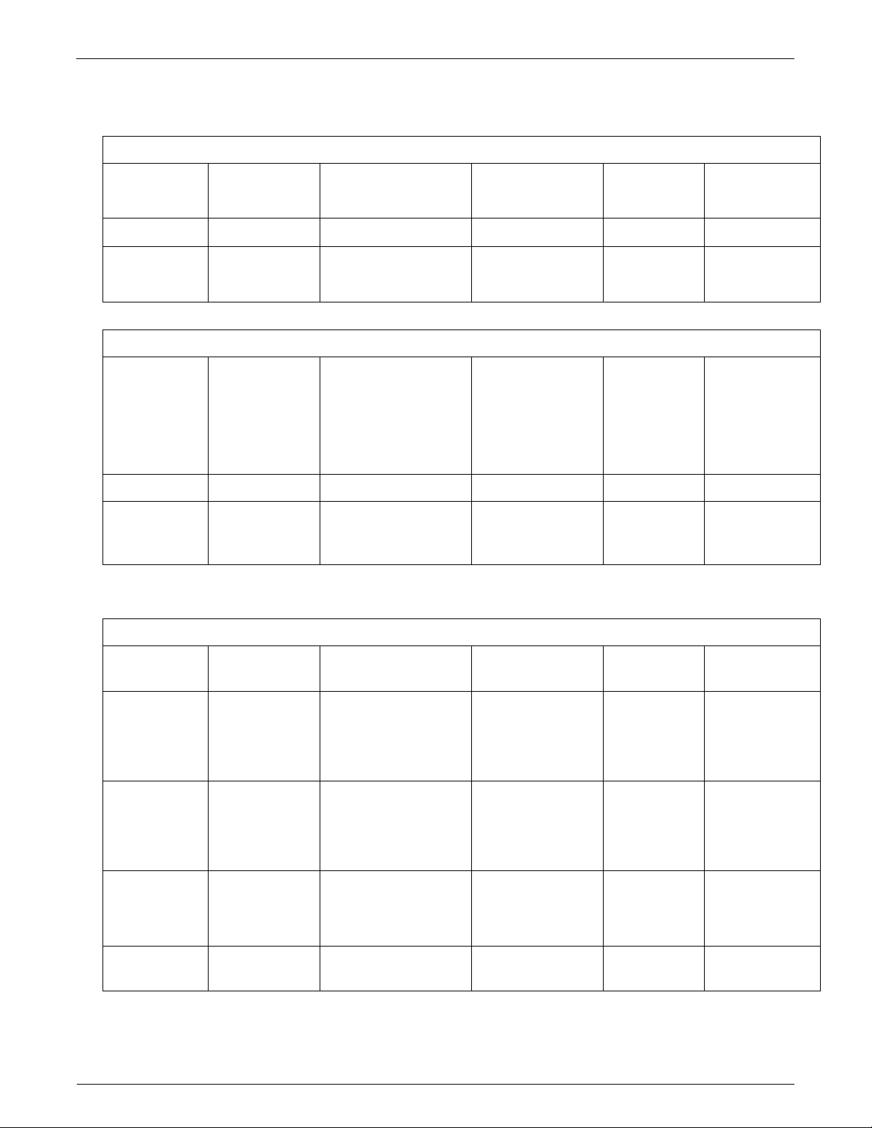
The complete 2852-FCS system consists of the probe, the PMC card, and the 2852 controller.
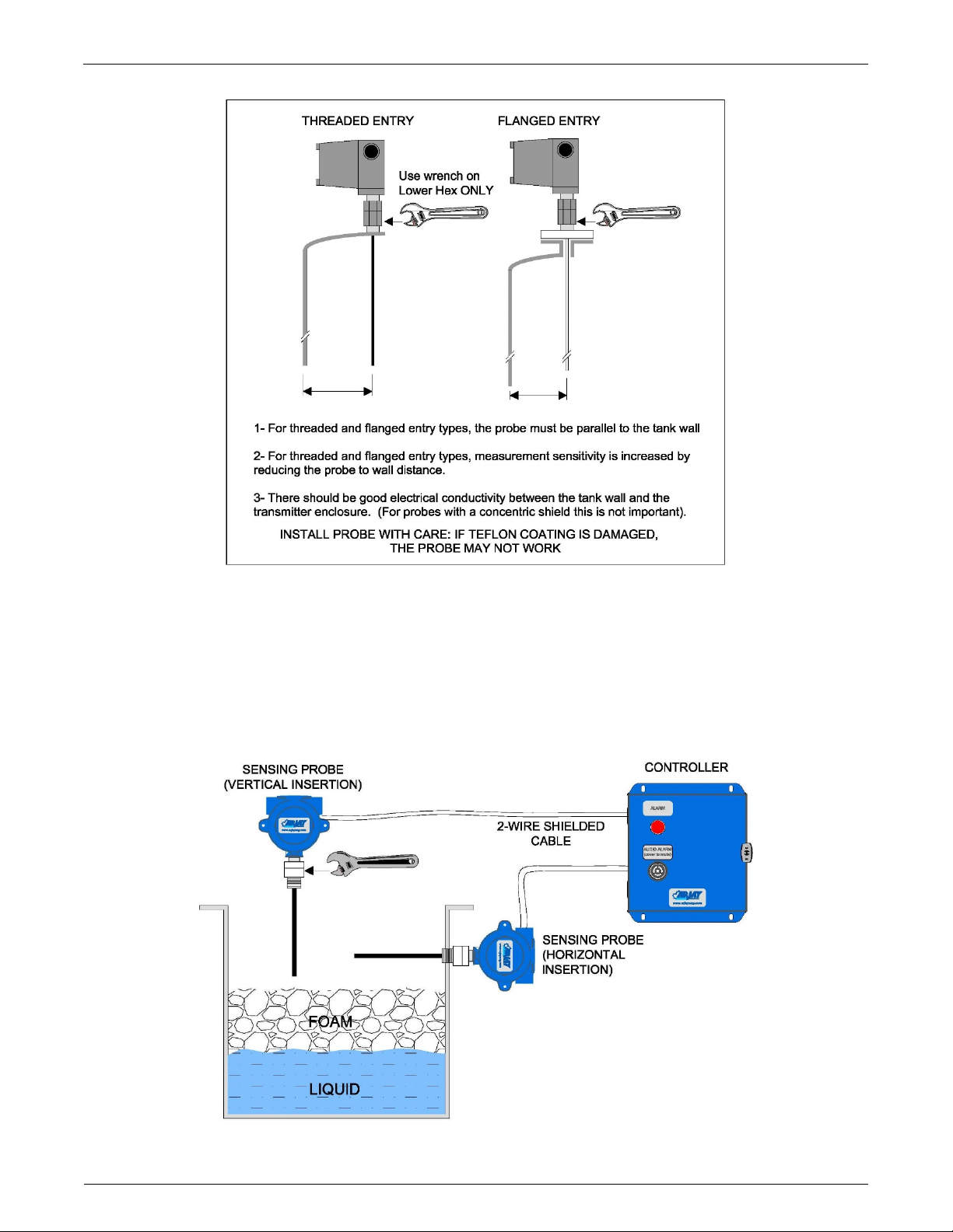
The standard probe is constructed of a Teflon coated SS rod. The PMC card is mounted in a
junction box mounted on top of the probe. The PMC card translates the capacitance signal from
the probe into a frequency pulse, which is then transmitted up to one kilometer to the 2852
controller via 2-wire shielded cable.
Probes can be inserted vertically, horizontally, or angled into the tank. The sensor does not
differentiate between liquid and foam. This system is designed to alarm for foam presence in a
normal air condition.
On vertical and angled probes, the two relays can be set at the same or different levels. Each relay
also has a differential setpoint to allow the relay to activate at one level and de-activate at a
different level. This is similar to a latching format which can cycle a valve or control action between
two points through the use of only one relay. For example, the defoamer spray can be activated at
a high point and held on until the foam reaches a desired lower point.
On a horizontal insertion, both relays are calibrated to the same setpoint.
For single point high foam level applications, it is typical for both relays to be calibrated without
bringing the foam level up to a specific alarm point. For example, in a high alarm application, the
controller can be calibrated to air. An alarm will occur when the foam approaches and begins to
cover the probe.
This model is intended for use in General Purpose non-hazardous areas. For hazardous
location use refer to Arjay Engineering Ltd. for the appropriate model.
1.1 Features
Microprocessor based capacitance Controller
Relay and 4/20mA alarm output
Modbus protocol via RS-485 for access by Arjay handheld, Central Access Panel or
compatible system
Local Auto calibration or remote calibration via network
User specified custom features may be added by contacting Arjay Engineering Ltd.
1.2 Model Number vs. Voltage Input
2852-FCS-1 100-240 VAC power input
2852-FCS-3 12 VDC power input
2852-FCS-4 24 VDC power input

Model: 2852-FCS User Manual Rev: 1.0
4
1.3 Specifications
Power Input: 12 VDC +15% /-10% or 24 VDC +15% /-10%, 250mA maximum
100VAC – 240VAC +/- 10%, 50/60 Hz, 150mA maximum
Note: DC input models must be supplied by Limited Energy power source.
Limited Energy means compliance with one of the following requirements:
- Class 2 circuit according to Canadian Electrical Code, Part, I, C22.1;
- Class 2 circuit according to National Electrical Code, NFPA-70;
- Limited Power Supply (LPS) according to IEC 60950-1;
- Limited-energy circuit according to IEC 61010-1.
Connections to mains supply Permanent (for AC/DC model)
User Interface:
Display & Keypad Two line LCD with Alarm status display, select menu or enter
values by keypad (display is internal to housing and used for
set-up and diagnostics only)
Communication Interface: Modbus (RS485)
Analog /Relay Outputs:
mA Signal Output
4 mA during Normal and 20 mA during an alarm condition, 900
Ohms max OR 450 Ohms max (12VDC Power)
*Set for Relay 1 only
Relay Output
2 SPDT relay, dry, N.O. Contact 5A @ 250 VAC (Resistive) and
N.C. Contact 3A @ 250VAC (Resistive), selectable failsafe or
non-failsafe, selectable high or low acting alarm, programmable
time delay: 0 – 600 seconds
Instrument Performance:
Measuring Range 0 - 5000 pF (most applications are 100pF to 1000pF)
Accuracy 0.2% of setpoint
Resolution 0.05% of setpoint via network display
0.002% of Full Scale capacitance via network display
Calibration Single point per relay: Auto calibration
Environmental:
Operating conditions Continuous
Operating Temperature -20 °C to +55 °C controller
-60 °C to +55 °C PMC
-60 °C to + 260 °C probe
Relative humidity 0 to 95% (non-condensing)
Altitude ≤2000 m
Installation Category II
Pollution Degree 2

Model: 2852-FCS User Manual Rev: 1.0
5
Equipment mobility Fixed
Mechanical Specification: Refer to Dimensional Drawing
Enclosure Rating Type 4 / IP65 Painted Steel (Blue)
Type 4x / IP66 Polycarbonate (Gray)
Type 4x / IP66 316 Stainless Steel
Options on Enclosure Buzzer (Tagged to Alarm 2 setting)
Pilot Light OR Strobe/Beacon (Tagged to Alarm 2 setting)
Custom alarms
Approval Standards: UL / IEC 61010-1, 2nd Edition, 2005-07-22 (Electrical
Equipment for Measurement, Control, and Laboratory Use;
Part 1: General Requirements)
UL file number: E343390
CAN/CSA-22.2 No. 61010-1, 2nd Edition, 2004-07,
(Electrical Equipment for Measurement, Control, and
Laboratory Use; Part 1: General Requirements)
CE: UL / IEC 61010-1; IEC / EN 61000-4; ISO 9001:2008

Model: 2852-FCS User Manual Rev: 1.0
6
2.0 INSTALLATION
NOTE: If any damage to the instrument is found, please notify an Arjay Engineering
representative as soon as possible prior to installation.
2.1 Controller Installation
Choose the mounting location in accordance with good instrument practice. Extremes of ambient
temperature and vibration should be avoided (see specifications and installation drawing).
The 2852-FCS controller may be mounted up to one kilometer from the PMC card using a
minimum 18 gauge, 2-wire SHIELDED cable.
Check the polarity of the + and - wiring between the controller and the PMC prior to powering on
the unit; + to + and - to - to avoid damage. Shield of cable should be connected to secondary
ground terminal marked as . Incoming Earth ground should be connected to primary ground
terminal marked on sub plate.
Important Note: The controller is factory set in a Failsafe mode. This means that the relays
are in an energized state during normal operation. The N.O. relay contact will be held closed and
the N.C. relay contact will be held open during a normal condition. This will allow the relay to return
to its non-energized (shelf) state during an alarm, fault or power failure condition. Wire accordingly.
Note: Maximum Conduit size for installation size is ¾” FNPT.
2.1.1 Permanent Power Connection (AC Powered Models only)
1) Connection to the building wiring system shall be in accordance with the Canadian
Electrical Code (CEC), Part 1 in Canada, the National Electrical Code, ANSI/NFPA 70 in
the USA, or the local electrical codes of the country where the equipment is being
installed.
2) A disconnecting device is required. The disconnecting means shall disconnect all
current-carrying conductors.
3) 15A circuit breaker or equivalent fuse is required.
4) An external switch or breaker shall be in close proximity to the equipment and within
easy reach of the operator. The switch shall be marked as the disconnecting device for
the equipment and include the symbols to its “ON” and “OFF” positions using the
following symbols:
5) The wiring for AC power should be minimum 18 AWG / 300V or as required by local /
country codes.
6) After field wiring, the primary wires must be secured to the enclosure by tie-wraps to
maintain the separation from the signal wires.
7) Wiring diagram for permanent connection: See drawings at the back of this manual.
8) Use copper conductors only.
Power OnPower Off

Model: 2852-FCS User Manual Rev: 1.0
7
2.2 Probe Installation
The probe length is custom ordered to the tank or vessel requirements. On vertical and angled
installations, the probe must be long enough to reach the lowest alarm setpoint.
The PMC junction box should be mounted above any risk of flooding.
It is recommended to use a flange, union, or retraction device for easy retraction of the probe
from the vessel. This will also assist for routine testing and calibration.
Standard probe entry into a tank is via a 3/4" NPT opening (standard probes) or 1" NPT opening
(heavy duty probes). Flanges and concentric shields are available as options. The entrance
configuration may vary depending on the application requirements.
TO SCREW IN THE PROBE (THREADED ENTRY), USE A WRENCH ON THE LOWER
FITTING ONLY. The probe fittings are compression type with Teflon ferrules assembled by
applying torque between the two hex sections. The fittings are sealed at the factory to provide a
compression seal capable of withstanding high pressures. Once opened they cannot be
reassembled without new ferrules.
The probe orientation can be vertical, horizontal, or angled. The following points are important
when installing the probe:
1- Reference ground: This is important for accurate measurements when foam alarm points
are set along the length of a probe, as opposed to basic high alarms. The ground is
typically the metal walls of the tank. For non-metal tanks, a ground reference may be
necessary to ensure stable accuracy.
2- The distance between the probe and the ground reference: This only applies to probes
without concentric shields. The closer the distance to the tank wall, the greater the
sensitivity of measurement; too close and bridging problems may occur.
3- The measurement accuracy may be affected by the temperature change of the
material in the tank. The amount of measurement error depends on the material. If the
temperature change is excessive, temperature correction may be required. Contact the
Arjay representative for more information.
4- Agitators or moving objects in the tank: Moving objects in the tank close to the probe
such as agitator blades, moving baffles etc. appear as moving ground references to a
capacitance probe and will cause measurement errors. In applications where these objects
are present, a concentrically shielded probe should be used.
CAUTION: INSTALL THE PROBE WITH CARE: THE TEFLON SHEATH IS USED TO
ELECTRICALLY ISOLATE THE METAL PROBE FROM THE LIQUID. DAMAGE
CAUSING LEAKS MAY CAUSE READING ERRORS.

Model: 2852-FCS User Manual Rev: 1.0
8
Figure 1 – Probe Installation
NOTE:
To ensure proper operation and electrical safety, make sure the 2852 enclosure and
the PMC junction box are electrically grounded.
If the equipment is used in a manner not specified by the manufacturer, the protection
provided by the equipment may be impaired.
Figure 2 – Typical Application

Model: 2852-FCS User Manual Rev: 1.0
9
2.3 Electrical Installation
Figure 3 – Electrical Installation Overview
TB1/TB2 - Relay Output
2 SPDT relay, Dry, N.O. Contact 5A @ 250 VAC (Resistive) and N.C. Contact 3A @
250VAC (Resistive), selectable failsafe or non-failsafe, selectable high or low acting alarm,
programmable time delay: 0 – 600 seconds
TB3 - Power Input
Power input as per Model. Check if ordered AC or DC. . Earth ground is connected to G.
TB4 - Network Output
Connect RS485 + and – to the network D+ and D-.
TB5 - 4/20 mA Output (+ and -)
The 4/20 mA is a sourced output referenced to Ground. It is not loop powered.
4mA = Normal 20mA = Alarm
TB6 - Probe Input
Connect ‘+’ to ‘+’ , ‘-‘ to ‘-‘ between the controller and the PMC card. Check polarity to avoid
damage.
TB7 – Buzzer / Red Pilot Light Output (Optional)
The connection will be factory wired if ordered.

Model: 2852-FCS User Manual Rev: 1.0
10
2.3.1 Input / Output Terminal Specification
Input Terminals – Power Source
Terminal
ID Overvoltage
category Rated Voltage (V) Rated
Current/power
(A/W/VA)
___ HZ or
DC Specified
Mains
fluctuation
TB3 II 100-240V 150mA 50/60Hz
10%
TB3 II 12 OR 24V 250mA DC
15%
10%
Input Terminals – Measuring Circuits
Terminal ID Function Measurement
Category Nominal a.c. or
d.c line to
neutral voltage
/ if CAT I, Max.
transient
overvoltage Ut
Nominal
a.c. or d.c
current
Rating of
insulation
required for
external
circuit
TB6 Frequency I 15V,50mA / 0 -- DI * or RI**
TB4 RS485
Communicati
on
I 5V, 5mA / 0 -- DI * or RI**
* Double Insulation
**Reinforced Insulation
Output Terminals
Terminal ID Function Isolation or
protection Rated V, A Max. V, A Load type
and nominal
TB1 Load Relay N.O. Contact
5A@250VAC &
N.C. Contact
3A@250VAC
-- --
TB2 Load Relay N.O. Contact
5A@250VAC &
N.C. Contact
3A@250VAC
-- --
TB5 Current Isolator(optional) - 18V,20mA,
900
- 9V, 20mA,
450
50mA@18V --
TB7 Voltage None 24VDC, 30mA -- Buzzer / Pilot
Light

Model: 2852-FCS User Manual Rev: 1.0
11
2.4 Glossary of Symbols
Attention, consult accompanying documents
Attention, veuillez consulter les documents ci-joints.
Protective Earth
Terre de protection
Fuse
Coupe-circuit; fusible
Direct Current (DC)
Courant continu
Normally open relay contacts
Contacts travail
Normally closed relay contacts
Contacts Repos
Power off
ArróÕ (mise hors tension)
Power on
Marche (mise sous tension)
L
Live
Sous tension
N
Neutral
Neutre
G
Ground
Terre

Model: 2852-FCS User Manual Rev: 1.0
12
3.0 STARTUP AND CALIBRATION
3.1 Startup
Check that the power wiring and PMC wiring are wired in accordance with the electrical
installation drawing.
Power On the unit. Allow a 1 hour warm-up period before calibrating.
The Status LED on the controller circuit board should be green. A red Status LED indicates a
fault condition. If red, check the Troubleshooting section.
The unit is pre-configured and tested at the factory. However, a quick field calibration is
required after power up to tune the probe to the installation conditions. See section 3.3 to
calibrate the 2852-FCS.
3.2 Menu Flow Chart Background Information
The control setup, diagnostics, and calibration are accessed using the display and keypad on
the controller. The Flow Chart in Section 7.0 provides an overview to the various menus and
features. Keep a copy of the flow chart at hand when accessing the internal controller features.
Below is a description of the menu functions.
3.2.1 Menu Description
Since the 2852 controller has a small LCD, some menu descriptions may be in short form. The
following are the menu descriptions:
Diags: Diagnostics
Cal Pts: Calibration points
Auto Cal: Auto calibrate
Man Cal: Manual calibrate
Cal Ok: Calibrate ok
Cal Err: Calibrate err
mA out: mA output
mA Span: mA output span
Sec: Seconds
ALRM CAL: Alarm Calibration
Cal: Calibration point
SENSTVTY: Sensitivity
A1: Alarm relay 1
A2: Alarm relay 2
Alrm: Alarm
Alrm Lvl: Alarm level
Diff Hi: Differential Hi alarm set value
Diff Lo: Differential Lo alarm set value
Alrm Del: Alarm Delay
^SP: Relay Setpoint Hi action
vSP: Relay Setpoint Low action
3.2.2 Menu Description
The 2852 controller will display Normal in its normal operating condition and A1 or A2 for an
Alarm condition of Relay 1 or Relay 2.
From the main menu, you can select Cal Only, View, and Change.
Cal Only allows a user to calibrate after the equipment is installed. The calibration is required at
site after power up or anytime a component or sensor is changed out. A password is required
to enter this and is described in the calibration section.
View allows an operator to view the Calibration setpoints in pF, the Alarms settings (2852
only) such as low or high action, failsafe or non-failsafe and the 0-600 second delay, the
Diagnostics of raw readings and the Setup values such as mA output and ID address. This
can be viewed without a password and without risk of changing any values. This information
may be requested during technical assistance inquiries.

Model: 2852-FCS User Manual Rev: 1.0
13
Change is password protected and allows an operator to enter or change the configuration set-
up values indicated in the View. Changes will be required for the initial setup of relay setpoints,
delays, span etc. or to re-set the values to the factory default.
3.2.3 Data Entry
3.3 2852 Controller Calibration
Power up the 2852 Controller. The status LED should be green. The LCD will scroll to the
normal operating screen after a series of the following screens (each display for 2 sec.). It may
read Normal or A1 A2 until a calibration is performed.
3.3.1 Site Calibration
For a single point high foam alarm, the foam level may not need to be changed.
For a high alarm application, a vertical or horizontal probe can be in air and well above the liquid
or foam. The probe is calibrated to air and as the foam reaches the probe, it will alarm.
For a low alarm application, a horizontal probe can be fully submerged in foam during
calibration. The probe is calibrated to the foam and as the foam interface drops below the
probe, it will alarm.
However, on vertical probes, if the alarm setpoint is desired at a specific point along the length
of the probe, or if the differential control is being used, a foam level change during calibration
will be required. If a second HI alarm is required then the foam will also need to rise to this
desired level. The buzzer and light options are tagged to the 2nd Alarm point.
The following are the basic steps for setting up two alarm points each with a HI/LO differential.
Refer to the Flow Chart for a detailed set-up and calibration.
Check that the foam or liquid is at the desired level for calibration (ie. that the probe is in air for a
typical high level alarm application).
Press and hold Menu key for 5 seconds to enter the main menu. The display will read the first
menu item Cal only. Press select key, enter password ¨2000¨.
The display will read Select Cal A1. Press Select to calibrate the first setpoint of Relay 1. This
can be either the HI or LOW point of the differential.
This display will read A1 PT 1 with a pF reading of the probe displayed. Press select to
acknowledge and then press select to confirm the new calibration.
The display will read A1 PT 2 with a pF reading. This is the second point for Relay 1. For a
single point alarm without differential this will be the same point. Press select to accept this
second point. If differential control on the relay is required, change the foam level to the new
setpoint level and press Select.
Arjay
2800
S XXXXXX
PMC= EXT
SW X.XXX
HW
FCS
Normal
Normal Screen
NET ID:
X

Model: 2852-FCS User Manual Rev: 1.0
14
The menu will now guide you through setting up the second relay (A2) setpoints. If a buzzer or
light was supplied with the unit, they will activate at the Alarm 2 setting. If your application is to
have all alarms active at the same point, calibrate Alarm 2 as you did for A1. If you require
Alarm 2 to be at a higher setpoint level, you will need force the foam level up to the desired
alarm point on the probe before calibrating Alarm 2. This second point may be required in case
the foam continues to rise due to a defoamer failure or lack of chemicals.
When complete, Select EXIT.
This will get you back to the main menu of “CAL ONLY”. Press arrow down until you get to
“EXIT” in order to get back to main screen OR go to “Change” if different relay configurations
are required.
THIS COMPLETES THE SETUP AND CALIBRATION PROCEDURE FOR THE
2852-FCS Foam Control Switch

Model: 2852-FCS User Manual Rev: 1.0
15
4.0 SETUP AND ALARM
4.1 2852 Controller Setup
The 2852 controller has the following Setup parameters:
1. Sensitivity
The sensitivity determines the amount of pF change required to cause an alarm. The
factory default setting is 1.0 pF. The most sensitive setting is 0.1 pF. Increasing the pF
value will increase the amount of foam required to cause an alarm. Since different foams
have different dielectrics, a pF to mm of foam relationship cannot be factory determined. If
this is changed in the field, it should be tested to confirm an alarm.
2. Alarm Calibration above or below setpoint
This setting advises the controller if the calibration setpoint is above or below the alarm
condition. For high alarm applications, the alarm condition is above calibration setpoint. This
indicates that the pF value must increase above the setpoint to activate the alarm. For low
alarm applications, the alarm condition is below the calibration setpoint. This indicates that
the pF value must decrease below the setpoint to activate the alarm. The factory default is
Alarm = ^SP
3. Defaults
Factory settings are pre-configured into the unit based on the most typical set-up required
for this application. This provides for a quick and easy calibration at site but can be
changed for special applications. If the setup has been changed, this will change back to the
factory defaults.
4. Net ID
The ID number is used only for network applications. To communicate on a network, each
controller must have a unique ID number. The factory default ID number is 1.
Important: If multiple units on a network have the same address, network errors will result.
5. Filter
Data filtering is used to smooth data from a sudden change and minimize fluctuating
readings. For example, a 5 second setting means the calculated value of the capacitance
and resulting values of pF will start to respond immediately but will take 5 seconds to reach
their final values. The factory default is 0 to provide an immediate and active response.
4.2 2852 Controller Alarms
The two relays on the 2852-FCS operate independently. They are named A1 and A2. The
follow parameters are available to set up each of the relays.
1. Delay. Minimum time in seconds for an alarm to exist before the relays change to an alarm
state. The relay alarm state depends on the Relay Action and Failsafe settings. The factory
setting is 0 seconds.
2. Action. This determines if the Alarms LEDs should activate when the pF reading rises
above or below the setpoint. The factory default is above the setpoint because the
application of air to foam is an increase in capacitance.
3. Failsafe. Failsafe typically means that the relay is held in an energized state when in a
normal operating condition as opposed to an alarm condition. In an alarm condition, the
relay de-energizes which is identical to when the instrument power is shut off. The rationale
is that the alarm condition should match the Power Fail condition. The factory default is
Yes for Failsafe.

Model: 2852-FCS User Manual Rev: 1.0
16
Example Of Single Point Alarms (No Differential) Applications
Figure 4 – No Differential Application – High Level
Figure 5 – No Differential Application – Low Level

Model: 2852-FCS User Manual Rev: 1.0
17
4.3 2852 Controller Network
The 2852 Controller may be monitored and calibrated via RS-485 protocol compatible digital
communications.
Typical features are:
1. Ease of wiring in multiple level point monitoring:
Up to 255 Model 2852's (or other Arjay 2800 Series level monitors) may be connected together
in a daisy chain (2 wire communication plus power wiring) connection to an Arjay Remote
Access monitor or customer control system which allows viewing data and setup of any of the
transmitters on the network. The relay and analog outputs may still be used if necessary.
2. Setup for the 2852 for network operation:
Each 2852 transmitter must have a unique ID number to connect in a network system.
4.3.1 Modbus Configuration
Parameter settings: 9600 Baud Rate; Even Parity, 8 Data Bits and 1 Stop Bit.
Wiring connection: RS485 (+) connect to D+; RS485 (-) connect to D-.

Model: 2852-FCS User Manual Rev: 1.0
18
4.3.2 2800 Series Modbus Register Mapping
REG Zero
Based DESCRIPTION TYPE
No. of
Reg
40001 0 Serial Number float 2
40003 2 Hardware Rev / Software Rev byte 1
40004 3 Sensitivity / Mode byte 1
40005 4 Instrument Status int 1
40006 5 Model / Modbus Address byte 1
40007 6 Relay2 Setup / Relay 1 Setup byte 1
40008 7 Password int 1
40009 8 XA "A" cal parameter float 2
40011 10 XK "K" cal parameter float 2
40013 12 XC "C" cal parameter float 2
40015 14 Filter float 2
40017 16 Slope – pF per % level float 2
40019 18 Offset – pF for empty vessel float 2
40021 20 mA output span value float 2
40023 22 mA output Zero value float 2
40025 24 mA output Trim Slope value float 2
40027 26 mA output Trim Offset vlaue float 2
40029 28 Cal1 PV: 1st calibration point level value in % float 2
40031 30 Cal2 PV: 2nd calibration point level value in % float 2
40033 32 Cal1 pF: 1st calibration point capacitance value in pF float 2
40035 34 Cal2 pF: 2nd calibration point capacitance value in pF float 2
40037 36
Relay 1 : Differential High Alarm [% Level]. Only used for
Linear Level type. Not used for Single Point Alarm application float 2
40039 38
Relay 2: Differential High Alarm [% Level]. Only used for
Linear Level type. Not used for Single Point Alarm application float 2
40041 40
Relay 1: Differential Low Alarm [% Level] OR Single Point
Alarm [pF]. Single Point Cal: used as captured pF during cal float 2
40043 42
Relay 2: Differential Low Alarm [%Level]. Only used for Linear
Level type. Not used for Single Point Alarm application float 2
40045 44
Relay 1 On delay [in seconds]. Only used for Linear Level or
Single Point Alarm application int 1
40046 45
Relay 2 On delay [in seconds]. Only used for Linear Level
type. Not used for Single Point Alarm application int 1
40047 46 mA Analog Output float 2
40049 48 Oscillation Frequency float 2
40051 50 Frequency float 2
40053 52 Capacitance float 2
40055 54 Filtered Capacitance float 2
40057 56 Level float 2

Model: 2852-FCS User Manual Rev: 1.0
19
5.0 MAINTENANCE
There is no routine cleaning required for this controller.

Model: 2852-FCS User Manual Rev: 1.0
20
6.0 TROUBLESHOOTING
CONDITION DO THIS
1. Status LED is OFF and the LCD
display if off
Check the power to the unit. If the unit is a 12VDC or
24VDC model, check the external source and polarity
is correct. If the unit is a 100-240VAC model, then
check the Line, Neutral and Ground wiring is correct.
2. If the status LED is RED This indicates a major error such as memory failure,
no probe signal etc. Check the following:
Make sure the PMC is installed
Make sure the PMC wiring is correct and there
are no breaks in the wiring. At the controller,
measure across the Probe Input terminals with a
DC meter. Make sure “Common” lead of meter is
on ‘-‘ terminal. It should read (+) 8 to (+)10 VDC
with the PMC connected and approximately 20 to
24 VDC with the PMC terminal disconnected.
Microprocessor may have lost its parameters due
to a surge in the line. Go to Diagnostic Menu (see
Flow Chart) to check the Calibration values,
frequency and capacitance values
Call Arjay Technical Support.
3. No mA output OR incorrect mA
output.
IMPORTANT: THE UNIT SOURCES mA OUT
FROM THE mA OUTPUT TERMINAL. THIS
TERMINAL SHOULD NOT BE CONNECTED TO
+24V. IT IS NOT A 2 WIRE mA TRANSMITTER.
See Figure 4 for Electrical hookup details.
Disconnect external wires from mA output and
measure with mA Meter.
Check the mA output Action (direct or inverse)
and mA output Span are set as desired. See
section 6.0 Flow chart / Change menu.
If the mA output still does not match the level,
then call Arjay Technical Support.
4. False Alarms
Add some time delay in the unit
Make sure there is no external interference and
electrical noise such as agitators, high voltage
interference, turbulent flow, etc
Adjust the sensitivity to the next higher value. Test
after any changes to confirm an alarm
ARJAY ENGINEERING TECHNICAL SUPPORT
(800) 387-9487
+1 (905) 829-2418
www.arjayeng.com
Table of contents
Other ARJAY ENGINEERING Switch manuals
Popular Switch manuals by other brands

Pakedge Device & Software
Pakedge Device & Software SW24-GBP user guide

HPE
HPE OfficeConnect 1820 Series Quick Setup Guide and Safety Information

Crestron
Crestron Sonnex SWE-8 Operation guide

H3C
H3C S5510 Series Operation manual

ELC
ELC dmXLAN switch8GB user manual

Cabletron Systems
Cabletron Systems pmn user guide