6
Unpacking and Assembly
Preparations
Remove the wooden lid, and then the box covering the
product. Check the contents of the inside boxes with
included parts.
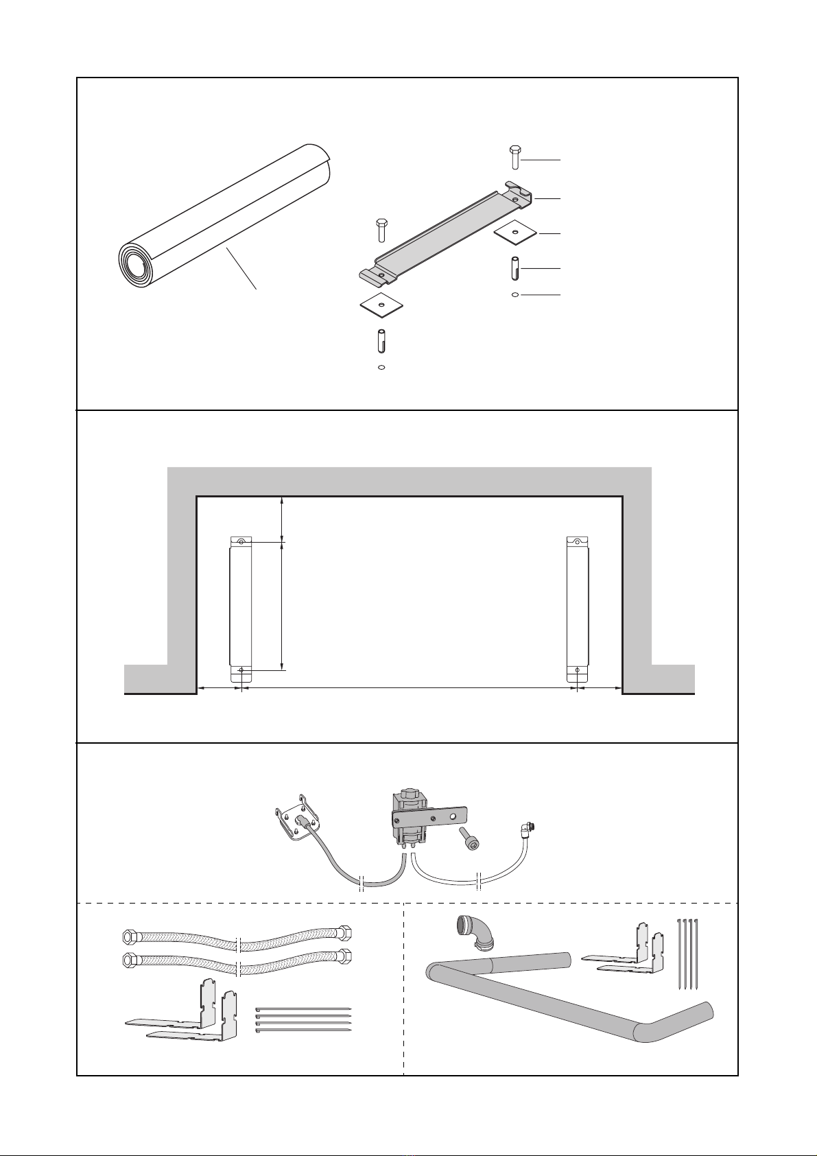
Floor attachments
The sliding rails provided in the installation kit have
to be used when installing Freedom Bath. The floor
construction must be suitable for anchoring the bolts.
For exact positioning of the two sliding rails a template
is provided. (
See figure1
.)
1 Place the template on the floor with the back edge
against the finished wall, and flatten it out so that no
creases are present.
2 Center the template so that the space around the
edges is even if you are in an alcove and located
where you want the edge in all other installations.
3Placethe sliding rails on the corresponding drawings
on the template.
4 Use a sharp pointy (Nail, punch etc) object to mark
out the center of the attachment holes onto the sur-
face underneath the template.
5 Remove the sliding rails and the template for now.
6Drill the anchoring holes and attach suitable anchors
depending on your floor structure.
7Make sure that the anchors are fully inserted into the
floor and that they are not protruding.
8 Place the sliding tracks in position. (
See figure 2.
)
9 Place a short level on the left rail and level it by
placing the necessary amount of adjustment spacers
underneath the rail.
10 Place a 4’level between the back of the two rails and
level them using the necessary amount of adjustment
spacers underneath the right hand rail.
11 Spacers are not always needed; please note that the
fewer used the better.
12 Levelthe rightrail inthe samemanner asthe leftrail,
placing adjustment spacers as needed under the front
of the rail.
13 Secure the anchors and verify one last time that the
rails are level in all directions. This is very important
as there are no adjustment possibilities once the tub
is installed.
Available kits (For special installations)
For the in this manual described alternatives for water
and drainage installations, the following kits are availa-
ble
(See figure 3)
:
AFA0090:
1Drainage pump with accessories
AFA0025:
A2water hoses 2400mm (94 4/8”)
B2holders
C4ties
AFA0045
A1coupling 90° 1 1/2”
B1drain pipe
C2holders
D4ties
Special tools
Not applicable
Pre-placement
Prior to moving the bath into final position, check:
Water service, stop and mixing valves, lines, spout etc.
(See Water Installation on page 10).
Provision is made for electrical service to interior junc-
tion box.
(See Electrical Installation on page 14)
.
House drain system ready for hook-up.
(See Drain
Installation on page 16)
.
Connect to the water supply for HOT and COLD water.
•
•
Flush the connection hoses prior to connecting to
the mixer.