Armagard PDS 32 User manual

PDS-32/42/46/47/52/55
www.Armagard.com
Installation Manual Page | 1
Toll Free (US): 1-866-434-0807
Call (UK): 0121-608-7210
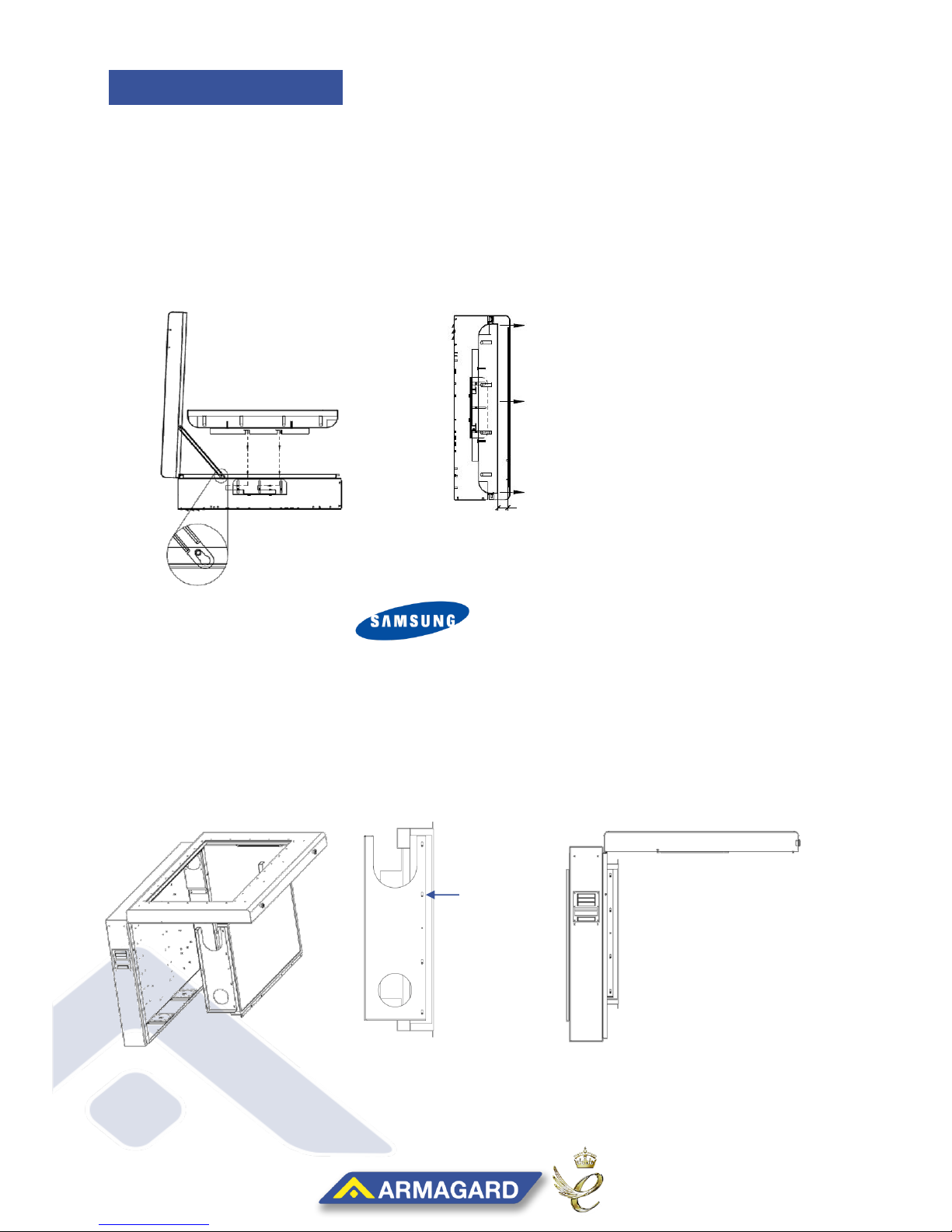
ARMAGARD PDS 32/42/46/47/52/55 –DISPLAY & WALL MOUNTING
(ENGLISH)
The following manual details the vital
information and safety precautions needed
for a safe installation of the Armagard PDS
landscape enclosure.
Due to the weight of your enclosure and for
personal safety, it is recommended to refer
to your company’s own health and safety
heavy lifting procedures before moving the
enclosure.
All power must be switched off until the
enclosure has been fully assembled and is
ready to use.
If your enclosure is for outdoor use, don’t
attempt installation in bad weather; use
correct lighting for optimum viewing
conditions.
Tools required for installation, Phillips
Screwdriver, Drill and Sockets Kit or Wrench
READ THIS MANUAL THROUGH BEFORE INSTALLING YOUR UNITS TO ENSURE CORRECT
INSTALLATION AND THAT YOU’RE COVERED UNDER WARRANTY.
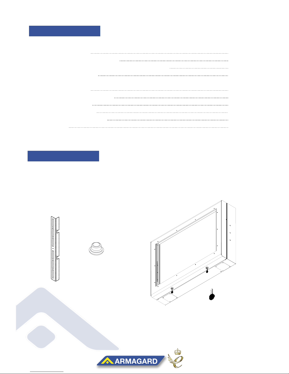
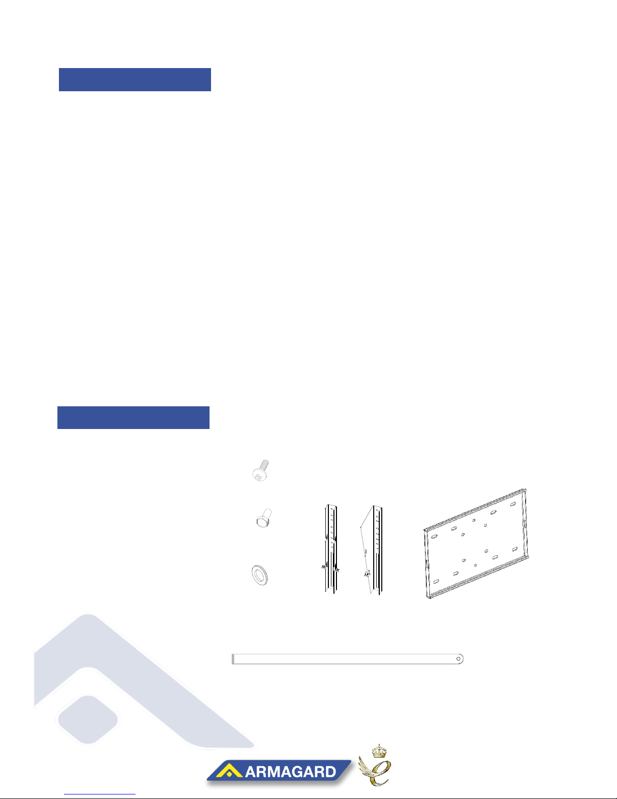
Electrical plugs, display bracket screws and
wall plate bolts are not provided because of
different customer setups.
Armagard recommends that all enclosures
should be securely attached to the wall
before fitting the display to avoid any
damage during lifting.
Default thermostat settings can be found on
page eleven.
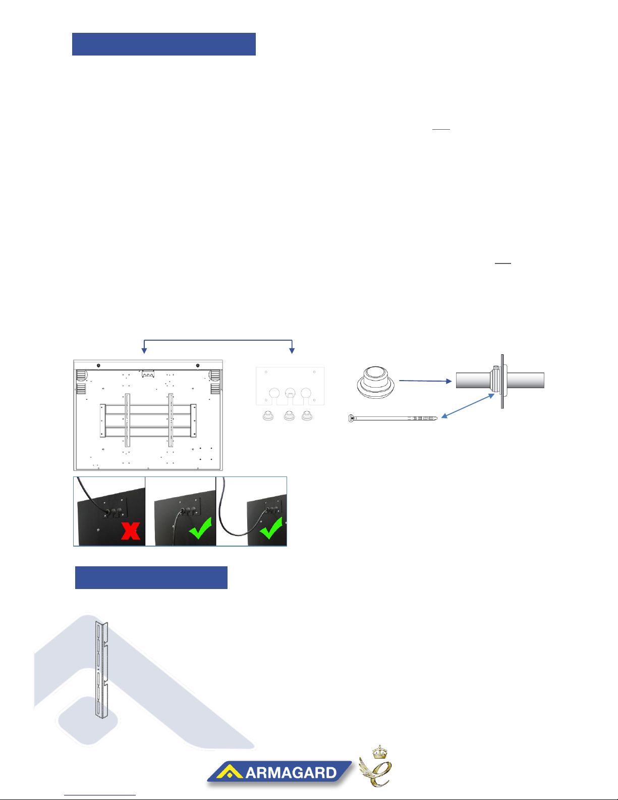
Because of its watertight seal, to lock an
enclosure you have to push firmly against
the door and then turn the key to lock.
32”-55”
INSTALLATION MANUAL
YOUR WARRANTY AGREEMENT IS VOID if you perform any modifications on the
enclosure, for example, drilling or penetrating any additional holes into the enclosure.
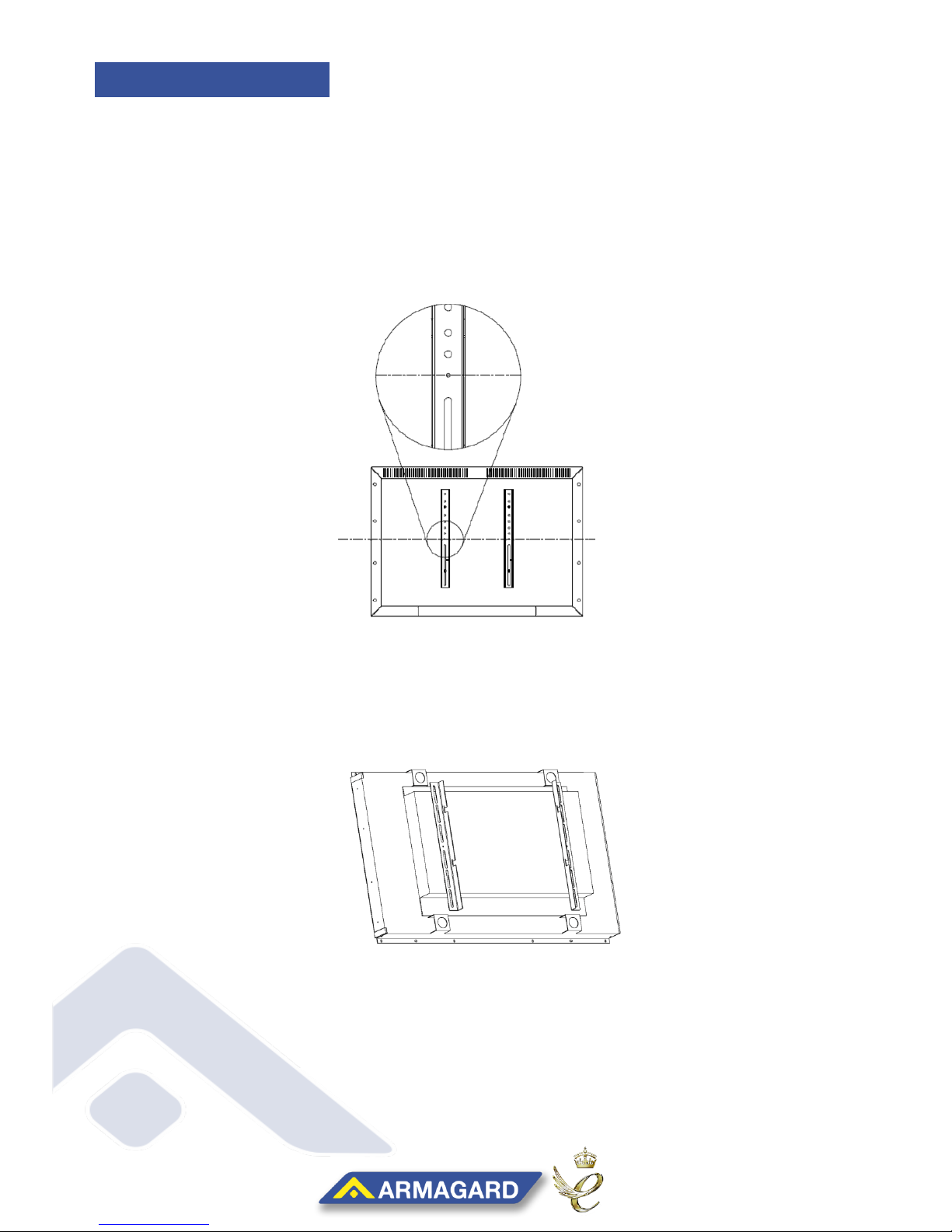
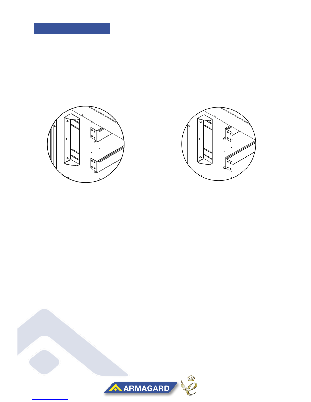
FOR BEST PRACTICE mount the enclosure using the recommended brackets to ensure
integrity.

PDS-32/42/46/47/52/55
www.Armagard.com
Installation Manual Page | 2
Toll Free (US): 1-866-434-0807
Call (UK): 0121-608-7210
M6 x 16 Bolts
x6
M6 x 16 Bolts
x6
Standard
enclosure
wall bracket
x2
15 deg enclosure
wall Bracket
(handed)
x2
Wall bracket x 1
Enclosure x1
Optional cealing mount
brackets
LCD Mounting
bracket
x2
Reversible
bracket x2
Keys
x4
Standard parts
Double ceiling
bracket x 1
Single ceiling
bracket x 1
M6 x 16 Bolts
x6
M6 x 16 Bolts
x6
Standard
enclosure
wall bracket
x2
15 deg enclosure
wall Bracket
(handed)
x2
Wall bracket x 1
Enclosure x1
Optional cealing mount
brackets
LCD Mounting
bracket
x2
Reversible
bracket x2
Keys
x4
Standard parts
Double ceiling
bracket x 1
Single ceiling
bracket x 1
1. PDS Enclosure x1
2. Keys x2
3. LCD Mounting Brackets x2
4. 20mm Open Grommets x3
Keys x2
20mm
Grommets x3
Display Mounting
Parts List Pg 2
Gland Plate & Cables Pg 3
Display Brackets (Inc. Samsung Hi-Bright) Pg 4-6
Finishing Up Pg 7
Wall Mounting
Parts List Pg 7
Enclosure Brackets Pg 8
Wall Plate Pg 9
Locking Bar Pg 10
Controller Board Pg 11-13
Maintenance Pg 14-15
CONTENTS
DISPLAY MOUNTING
CONTENTS
PARTS LIST

PDS-32/42/46/47/52/55
www.Armagard.com
Installation Manual Page | 3
Toll Free (US): 1-866-434-0807
Call (UK): 0121-608-7210
STEP 6:Check all apparatus for the installation is correct (Figure2)
LCD MOUNTING
BRACKET X2
Figure 2
(NOTE: Screws not provided –depends on display type) 4-6 needed, customer supplied
STEP 1:Unlock the door and position the enclosure on its back, securing the door stays within the
side pins.
STEP 2:Choose the location you want to place your media player by taking into account the size
of your display and the available space needed. Then secure just the cables from your
media player and display into the mains surge protector.
STEP 3:Carefully raise the enclosure up (Figure1) and feed the surge protectors main power
cable out through the gland plate at the back of the unit (remove plate if necessary).
STEP 4:Use either an open or closed grommet to fill the gland plate holes, while using cable ties
to secure any open grommets until they’re water tight and screw the gland plate back if
necessary (Figure1).
NOTE: Make sure any cables fed through the gland plate come from below, and do not come
down into the enclosure from above. Cables from above allow liquids to track this path into
the unit (Figure1.5).
STEP 5:Close and lock the enclosure, then proceed to make up the plug for the enclosures
main’s extension.
Figure 1.5
Grommets
(Gland Plate)
GLAND PLATE & CABLES
DISPLAY BRACKETS
Figure 1

PDS-32/42/46/47/52/55
www.Armagard.com
Installation Manual Page | 4
Toll Free (US): 1-866-434-0807
Call (UK): 0121-608-7210
(HALFWAY LINE)
STEP 7:Prepare a surface area to turn your display over, using appropriate covers to prevent any
damage being caused to its front.
STEP 8: Turn your display over and using measuring tape, determine the halfway line of the unit.
STEP 10: Using the diagram shown in Figure4, fasten the brackets with the 4 or 6 screws suited to
your LCD Display type.
Figure 3
Figure 4
STEP 9: For a balanced unit, align the centre hole of the bracket with the halfway line of your
display (Figure3) and determine equally spaced screw fittings, taking into account the
size of your display (adjustment may be required depending on screen type).
(NOTE: All cabling should now be complete; access to the back is limited once the display is secured)
DISPLAY BRACKETS

PDS-32/42/46/47/52/55
www.Armagard.com
Installation Manual Page | 5
Toll Free (US): 1-866-434-0807
Call (UK): 0121-608-7210
STEP 11: Unlock the door and position the enclosure on its back, securing the door stays within the
side pins. (For the Samsung Hi-Bright Screen, proceed to Step 14)
STEP 12: Then safely place your display into the enclosure using the interior mounting plate
(Figure5).
STEP 13: A gap of 15mm must exist between the air curtain and the enclosure window, any less
and you risk insufficient cooling to keep the display working (Figure6)
Figure
55
Figure 6
(0.59 INCHES)
(NOTE: For screen adjustment continue to STEP 16)
STEP 14: The Samsung Hi-Bright screen uses special side mounting to secure. Locating the fixture
holes located at both sides of the display; fasten side brackets using at least 3 of the
holes to secure the screen (Figure7).
STEP 15: Making sure all cables have been connected, lower the display into the enclosure and
secure with drill (Figure8), proceed to Step 18.
Samsung Hi-Bright Display
Figure 7
Fixture
Holes
Figure 8
DISPLAY BRACKETS

PDS-32/42/46/47/52/55
www.Armagard.com
Installation Manual Page | 6
Toll Free (US): 1-866-434-0807
Call (UK): 0121-608-7210
STEP 16: Adjustment instructions for the interior mounting plate.
To Raise: Loosen the screws and raise the interior bracket forwards and fasten to decrease
the distance from the LCD screen and the window (Figure9).
To Lower: Loosen the fittings, rotate the bracket, lower and fasten to increase the distance
between the display and the window (figure10).
Rotate brackets to lower.
Raise brackets to raise.
Figure 9
Figure 10
DISPLAY BRACKETS

PDS-32/42/46/47/52/55
www.Armagard.com
Installation Manual Page | 7
Toll Free (US): 1-866-434-0807
Call (UK): 0121-608-7210
M6 x 16 Bolts
x6
M6 x 16 Bolts
x6
Standard
enclosure
wall bracket
x2
15 deg enclosure
wall Bracket
(handed)
x2
Wall bracket x 1
Enclosure x1
Optional cealing mount
brackets
LCD Mounting
bracket
x2
Reversible
bracket x2
Keys
x4
Standard parts
Double ceiling
bracket x 1
Single ceiling
bracket x 1
M6 x 16 Bolts
x6
M6 x 16 Bolts
x6
Standard
enclosure
wall bracket
x2
15 deg enclosure
wall Bracket
(handed)
x2
Wall bracket x 1
Enclosure x1
Optional cealing mount
brackets
LCD Mounting
bracket
x2
Reversible
bracket x2
Keys
x4
Standard parts
Double ceiling
bracket x 1
Single ceiling
bracket x 1
STEP 17: Once the LCD fits correctly, remove the display, set down in a safe area and then
lock the enclosure
NOTE: Armagard recommend that all enclosures should be securely attached to the wall before
fitting the display, to avoid any damage during lifting.
NOTE: For maintenance advice, see pages 14-15 for filters, thermostats and display cleaning.
Proceed to (Figure 11)
PROCEED TO WALL MOUNTING
1. Wall Plate x1
2. Flat Wall Brackets x2 (or)
3. 15° Degree Wall Brackets x2
4. Locking Bar
5. Bolts and Washers
M8 x 16 Bolts x6
M8 Washers x6
M6 x 25 Screws x2
M6 x 25 Screws x2
M8 Washers x6
(Fitted on Enclosure)
M8 x 16 Bolts x6
(Fitted on Enclosure)
WALL MOUNTING
Locking Bar x1
Wall Bracket x1
FINISHING UP
PARTS LIST

PDS-32/42/46/47/52/55
www.Armagard.com
Installation Manual Page | 8
Toll Free (US): 1-866-434-0807
Call (UK): 0121-608-7210
M6 x 16 Bolts
x6
M6 x 16 Bolts
x6
Standard
enclosure
wall bracket
x2
15 deg enclosure
wall Bracket
(handed)
x2
Wall bracket x 1
Enclosure x1
Optional cealing mount
brackets
LCD Mounting
bracket
x2
Reversible
bracket x2
Keys
x4
Standard parts
Double ceiling
bracket x 1
Single ceiling
bracket x 1
M6 x 16 Bolts
x6
M6 x 16 Bolts
x6
Standard
enclosure
wall bracket
x2
15 deg enclosure
wall Bracket
(handed)
x2
Wall bracket x 1
Enclosure x1
Optional cealing mount
brackets
LCD Mounting
bracket
x2
Reversible
bracket x2
Keys
x4
Standard parts
Double ceiling
bracket x 1
Single ceiling
bracket x 1
M6 x 16 Bolts
x6
M6 x 16 Bolts
x6
Standard
enclosure
wall bracket
x2
15 deg enclosure
wall Bracket
(handed)
x2
Wall bracket x 1
Enclosure x1
Optional cealing mount
brackets
LCD Mounting
bracket
x2
Reversible
bracket x2
Keys
x4
Standard parts
Double ceiling
bracket x 1
Single ceiling
bracket x 1
STEP 18:Check all apparatus for the installation is present and correct (Figure13) –Depending on
your setup you will have either (2) flat or (2) 15 degree wall brackets.
M8 x 16 Bolts x (4-6)
M8 x 16 Washers x (4-6)
Figure13
STEP 19: Position your enclosure for clear access to its back panel and remove the fitted washers
and bolts.
Figure14
STEP 21: For a balanced unit, align the centre hole of the bracket with the halfway line of your
display (Figure14). Making sure the mounting slots are fitted to the lower half of the unit,
then equally space and secure the brackets with M8 washers and bolts.
STEP 20: Using a measuring tape, determine the halfway line of the unit from top to bottom.
ENCLOSURE BRACKETS
Mounting slots on
the lower half

PDS-32/42/46/47/52/55
www.Armagard.com
Installation Manual Page | 9
Toll Free (US): 1-866-434-0807
Call (UK): 0121-608-7210
STEP 22: Check all apparatus for the installation is present and correct (Figure15)
STEP 23:Mark the chosen area for the wall plate making sure it’s completely level then secure the
plate with the lip facing upwards (figure15), using appropriate fixtures capable of
supporting the load (M8 bolts and suitable wall plugs).
.
STEP 24: After making sure the enclosure brackets and wall plate are securely tightened, steadily lift
the enclosure onto the wall plate and secure, ensuring the brackets are slotted over the
wall plates top lip and the enclosure doesn’t touch the wall (Figure16) – If necessary,
reposition the bracket arms to accommodate more room.
STEP 25:Finally use both M6 x 25 screws on the outward facing sides of both enclosures brackets
then tighten with a Phillips screw driver until the bracket and wall plate are clamped
together tightly (Figure17).
2 –M6 x 25 Screws
(NOTE: Wall Plate fixtures not provided –depends on surface type) minimum of 6 bolts, customer
supplied.
Figure15
Figure17
Figure16
Upward lip
WALL PLATE

PDS-32/42/46/47/52/55
www.Armagard.com
Installation Manual Page | 10
Toll Free (US): 1-866-434-0807
Call (UK): 0121-608-7210
STEP 26: Check all apparatus for the installation is present and correct (Figure18)
STEP 27:Check the enclosure over to make sure it’s correctly attached to the wall.
STEP 28: To fully secure the unit to the wall and prevent issues of theft, take the locking bar and
feed it through the slots on the mounting brackets and plate (Figure19)
STEP 29: Attach a padlock (Not Supplied) and once the locking bar is secure, open the enclosure
and secure the cables then display, then lock up and power up.
LOCKING BAR
Figure19
Figure18
All done. Thank you... The Armagard Team

PDS-32/42/46/47/52/55
www.Armagard.com
Installation Manual Page | 11
Toll Free (US): 1-866-434-0807
Call (UK): 0121-608-7210
The printed circuit board (PCB) automatically manages the on-off commands for an
enclosures air curtains and fans, heaters, and media off switch. To reconfigure the controller
board, you’ll need the setup kit which is provided by Armagard as an optional extra.
All controller boards are automatically set-up with default temperatures (below), if you want
to change these settings then follow the below instructions.
Defaults: Fans on @25°C, Heaters @10°C, Media off (high) @42°C and (low) @0°C
Defaults: Fans on @77°F, Heaters @50°F, Media off (high) @107.6°F and (low) @32°F
NOTE: Not all units are equipped with a controller board. If your unit is not equipped with a
controller board, then it will use automatic thermostats instead. Details on how to use the
thermostat are found in the maintenance section (Pg14).
Kit Needed:
Armagard USB Cable
Armagard USB Drivers
Windows 7 Laptop
Phillips Screwdriver
Directions:
1. Locate your Armagard USB cable and terminal software, and have them placed to
one side.
2. To configure the PCB you’ll need a computer (ideally a laptop) which will be close
enough for the USB cable to reach.
3. Place the terminal software on your computer, if you’re running a Windows 7
computer then the drivers should be automatically installed. If not, then install the
CP210x drivers and select the appropriate 32bit or 64 bit driver. Make note of the
‘Terminal’ icon which we’ll come back to later.
4. Once the drivers are installed, you then need to locate the controller board within
your enclosure (figure 1). NOTE: Make sure the enclosures power is switched off and
unplugged before removing the cover to avoid a risk of an electric shock.
Figure 1
CONTROLLER BOARD SETUP

PDS-32/42/46/47/52/55
www.Armagard.com
Installation Manual Page | 12
Toll Free (US): 1-866-434-0807
Call (UK): 0121-608-7210
5. Use a Philips screwdriver to remove the steel lid that covers the PCB board and
place to one side.
6. Connect the USB cable to your computer and the 3-pin internal connection to the
setup port (highlighted red) on the controller board; located on the left hand side,
third from the top (figure 2).
Figure 2
7. Open up the terminal program mentioned from earlier and locate the setup port which
will appear as a COM port. Select the correct COM port from the drop down menu as
shown in figure 3 box 1. The correct COM port should be the last one on the list from
the drop down menu.
Figure 3
The default BAUD rate for setup is 115200 and the BAUD rate for info is 19200. These
can be selected from the pre-set figures shown in figure 3 box 2 above. Note - A BAUD
is a unit used to express the speed of transmission of electronic signals, corresponding
to one information unit or event per second.
8. Now click connect, highlighted in figure 3 box 3 above.

PDS-32/42/46/47/52/55
www.Armagard.com
Installation Manual Page | 13
Toll Free (US): 1-866-434-0807
Call (UK): 0121-608-7210
9. Once connected, press enter and the enclosures system will be switched off and a
menu will be displayed on the terminal program in box 5, the current settings will be
displayed for all the components just above the menu shown in box 4 below.
Figure 4
10. The settings for each component can then be changed by selecting the appropriate
option from the menu in box 5.
For example, to change the temperature at which the heater comes on enter ‘4’
followed by the return key. Then enter the new value followed by the letter ‘C’ (for
Centigrade) or ‘F’ (for (Fahrenheit) followed by the return key, such as 40C.
NOTE: The menu will time out after 30 seconds if no commands are received and the
system will switch back on.

PDS-32/42/46/47/52/55
www.Armagard.com
Installation Manual Page | 14
Toll Free (US): 1-866-434-0807
Call (UK): 0121-608-7210
To ensure your unit lasts as long as possible, take the following precautions.
Fan Filters –Every 6 months check and replace used fan filter pads and clean bug
screens if necessary.
oReplacement Filters are available in packs of 3
Check Enclosure Integrity –In an outside environment, make sure the enclosure and
its mounting bracket haven’t been damaged or moved.
THERMOSTAT CONTROL INSTRUCTIONS –To access enclosure thermostats firstly unlock
the enclosure (fixing the support arms), remove the display and manually adjust the thermostat dials.
Repeat process until fully optimised for your environment.
We recommend 25°C/77°F for cooling and 10°C/50°F for heating.
Simply turn the thermostat dial to the temperature you wish the component to turn on
at –it the fans are set to 40°C, the fans will activate once the internal temperate
reaches this heat, and then deactivate when the temperature recedes to a lower
temperature.
Be aware, these temperatures are just suggestion and the individual must take into
account all environmental factors before setting the thermostat. In addition the heat
given off by the LCD display will depend on whatever the customer chooses.
FAN MAINTENANCE & INTEGRITY
Check Enclosure Integrity –In an outside
environment, make sure the enclosure and its
mounting bracket haven’t been damaged or moved
by adverse weather conditions.
Screws & Padlock –Check the safety screws are
tight and padlock if the locking bar is secure and
not been tampered with.
To ensure your unit lasts as long as possible, take the following precautions.
ENCLOSURE STABILITY
MAINTENANCE

PDS-32/42/46/47/52/55
www.Armagard.com
Installation Manual Page | 15
Toll Free (US): 1-866-434-0807
Call (UK): 0121-608-7210
Screen Cleaning –Polycarbonate and Anti-Reflective Polycarbonate
In order to maintain your polycarbonate in a good condition it is recommended that the sheet be
cleaned periodically using suitable household cleaning agents.
The recommended cleaning instructions are as follows:
Use lukewarm water to rinse and soften dirt.
Make up a solution of lukewarm water and ordinary household cleaner or mild soap and use this
to wash the sheet.
A sponge or soft cloth should then be used to gently remove dirt and grime and for large areas a
pressure washer may be used in a suitable outdoor area.
Ethyl alcohol or white kerosene used sparingly can be used to remove paint and other such
substances.
The cleaning process should then be repeated and the sheet rinsed with clean water and dried
with a soft cloth.
Warning - The following precautions should be observed:
Do not scrub the sheet with brushes or sharp implements.
Do not use squeegees.
Avoid solvents, other than those listed, or any abrasive cleaners.
Avoid cleaners of a highly alkaline composition.
Avoid cleaning in the hot sun or high temperatures.
SCREEN CLEANING –GLASS DISPLAY
For high toughed glass and anti-reflective glass.
Procedure 1
1. On a mild temperature day, use hot soapy water and wash down the glass to eliminate all traces
of debris and marks.
2. When the window has been washed, rinse it thoroughly and using a clean cloth, dry the screen to
eliminate streaks and blemishes.
3. Alternatively you can use a glass cleaner detergent to get it thoroughly clean.
4. Note: Make sure you work as quickly as possible to avoid streaks appearing during the process.
BEST PRACTICE USE & WARRANTY
1. Mount the enclosure using the recommended brackets to ensure integrity. Do not drill or penetrate
any additional holes into the enclosure for mounting, as breaking the surface will reduce the ingress
rating, and void the warranty agreement.
2. Do not block air vents around the enclosure, obstructions to air circulation will cause overheating and
void the warranty agreement.
3. Do not use enclosures in environments or sheltered areas where the average ambient temperature is
higher than the operating temperature of your display without an air-conditioning module.
MAINTENANCE

PDS-32/42/46/47/52/55
www.Armagard.com
Installation Manual Page | 16
Toll Free (US): 1-866-434-0807
Call (UK): 0121-608-7210
For additional support, visit www.Armagard.com or call
Free (US): 1-866-434-0807
Call Free (UK): 0121-608-7210
This manual suits for next models
5
Table of contents