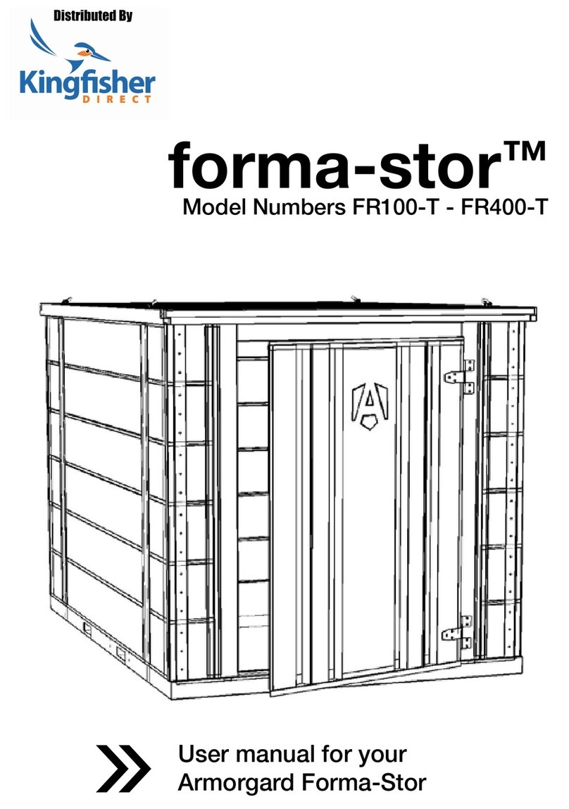
Armorgard forma-stor FR200-TT Quick start guide

forma-storTM
Operational and maintenance manual
Suitable for: FR200-TT, FR400-TT
1-877-794-2848 [email protected]

2
Welcome
Welcome to your Armorgard Forma-Stor. This quick-
assembly, modular solution for jobsite storage can be
easily built in as little as 10 minutes. Please consult this
manual for instructions on how to get the most from
the unit.
Please read this operational and maintenance
manual carefully prior to setting up the Forma-Stor.
Always keep this manual with the product and read
prior to use.

3
Contents
Safety information 4
Product specification 6
What’s included 7
Tools you’ll need 8
Getting to know your Forma-Stor 9
Padlock housing dimensions 11
How to assemble 12
Dismantling the Forma-Stor 15
How to install the locking rods 16
How to use the lock 18
Using the lifting eyes 20
Optional extras 21
Installing the shelves 22
Installing the ramp 23
Installing the BlokkaBar 24
Using the BlokkaBar 25
Storing the unit 26
Transporting the unit 27
Equipment care & ongoing maintenance 28
Warranty 29
Spare parts 31

4
Safety information
Before using the Forma-Stor, ensure any relevant risk assessments are carried out.
Armorgard cannot be responsible for accidents that occur due to negligence.
At least two people are required to erect or dismantle the Forma-Stor and all relevant
PPE must be worn while doing so. Never lift if not comfortable to do so.
TheForma-Stormustbepositionedonaat,solidsurface,andshouldbeleveland
stable before being used.
Ensure the Forma-Stor is fully assembled and that it is empty before lifting or moving it.
OnlyqualiedpersonnelshouldlifttheForma-Stor.
It is important to ensure that our guidelines are followed when assembling the Forma-
Stor, and extra care is needed when lifting panels.
Ensure that all parts are in good working condition prior to using the Forma-Stor.
Always lock the Forma-Stor when it’s not in use or out of sight. Do NOT leave keys
inside the unit while locking.
The unit is compatible with most padlocks (which are not included). We recommend
using the MasterLock #5 or the American Lock A50. Please contact a member of the
team if uncertain.
Only use UL or CSA listed electrical devices that meet the requirements of the local
jurisdiction.
Anymodicationtoorunintendeduseofthisproductcouldcreateadangerofan
explosion or other hazardous condition that can result in death, serious personal injury or
property damage.
Keep hands clear when closing door. Failure to do so could result in severe injury.
Thisproductisnotdesignedforstoringortransportingammables,explosives,
hazardous wastes or hazardous materials such as containers of solvents, gun powder,
dynamite, gasoline, propane, or acetylene tanks, etc.
5
While every effort has been made to ensure this operational and maintenance manual
covers every aspect needed to operate your product safely, please take care while using
the product and always operate with caution. Always liaise with management personnel
on site for any additional operational restrictions that you need to be aware of.
Lifting hazard. Single person lift could cause injury. Use assistance
when lifting.
Always follow safe lifting practices. You should stand as close to the
load as possible so you don’t exert more force onto your back by
extending the distance. Then bend your knees and keep your upper
body upright so your legs do the lifting rather than your back. Look
straight ahead and keep your back straight and shoulders back so
you have a slight arch in your lower back. Seek assistance from
another person or a lifting device if the weight exceeds what you are
comfortable lifting alone.
Do Don’t
Secure all locks when not in use Leave unlocked when unattended
Ensure parts are fully slotted together Leave keys or living things inside unit
Ensure it’s safe when opening/closing door Forget to do integrity checks before lifting
Ensureallcorrectxingsareused Position on an uneven surface

6
Product specification
Product
Code
Description Weight (lbs) External Dimensions
W x D x H (inches)
Internal Dimensions
W x D x H (inches)
FR200-TT Flat pack
store 845 81.7 x 79.1 x 81.3 75.4 x 72.4 x 73.4
FR400-TT Flat pack
store 1313 81.7 x 155.9 x 81.3 75.4 x 149.2 x 73.4
Individual panel
weight (lbs)
Back panel Door panel Side panel Roof panel Base
FR200-TT 123 168 117 117 249
FR400-TT 123 168 251 212 410

7
What’s included...
8x M12x45mm bolts
(FR200-TT)
12x M12x45mm bolts
(FR400-TT)
8x pipe linch pins
4x lifting eyes with rubber
washer
8x M12x20mm bolts
16x M12 washers
(FR200-TT)
20x M12 washers
(FR400-TT)
2x side panels
79x79” (FR200-TT)
158x79” (FR400-TT)
1x roof panel
79x79” (FR200-TT)
79x158” (FR400-TT)
1x base panel
79x79” (FR200-TT)
79x158” (FR400-TT)
1x door panel
79x79”

8
Tools you’ll need...
Screwdriver3/4” or adjustable
wrench
An impact driver
with 3/4” socket
1x rear panel
79x79”
Multiple
people
needed

9
Getting to know your forma-storTM
This quick-assembly, modular solution for jobsite
storage can be easily built in as little as 10 minutes.
Door
Side panel
Roof panel
Base
Rear panel
Side panel
Collapsible Stackable
Crane lifting
eyes
Forklift
pockets
Door
panel
T-Latch Lock

10
Crane lifting eyes
Padlock
housing Side access
forklift pockets
Data plate which
lists each unique
product serial
number
14 gauge and
19 gauge steel
Suitable for
use on-site
Add up to
5 shelves
Upgrade plates
for optional
BlokkaBar

11
Padlock housing dimensions

12
How to assemble
1.
4.
Familiarise yourself with all panels’
positions and orientation, i.e. the
top of each panel. Attach the crane
lifting eyes onto the roof.
Ensure it is supported safely while
you use the M12x45mm bolts and
washers to secure the side to the
base in two positions. Do not fully
tightenuntilallpanelsaretted.
2. With the base on a level, stable
surface, place one of the side panels
on the base, and support it in an
upright position.
3. Secure the side panel to the base
using two M12x20 bolts in each hole
along the side panel.

13
6.
7. 8.
Attach pipe linch pins in each corner.
This will enable the rear panel to
support the side panel. Then, secure
the bolts through the base as per
step 4.
There are two linch pins for each
corner. Secure the rear panel to the
base as described in step 3.
Place the other side panel on the
base, and secure it to the base panel
with bolts as described in steps 3-4.
Fit two linch pins in the corner.
5. Next, position the rear panel to
form a corner.

14
9. 10.
11.
Slot the door panel into place and
secure to the side panels with linch pins
as described in step 6, and bolts as
described in step 3 and 4. Ensure the
door is fully supported before opening
for the next step.
Now place the roof on top. The
roof is heavy and care should be
taken when lifting into position.
Please take all safety precautions
necessary when moving this part.
Extra people or equipment may be
required to lift safely.
Secure the roof panel to both side
panels using M12x45mm bolts and
washers in four positions on the
inside of the Forma-Stor.
12. Finally,fullytightenallxingsand
lifting eyes, ensuring that none
are missed.

15
Dismantling the Forma-Stor
1. 2.
To dismantle the Forma-Stor, remove
the parts in reverse order to which
they were assembled.
Removetheroofrst,followedby
the door panel, a side panel, the rear
panel, and then the remaining side
panel. Bolts can be threaded back
into the panels for safekeeping.
3. The Forma-Stor can then be stacked
initsat-packedform.Pleasenote
that you MUST remove the locking
rods before dismantling.

16
How to install the locking rods
4. Align the perforations of the angle
with the rivet nuts already located on
the door and use a washer and bolt
to secure the angle bracket in place.
3. Take the upper support angle and
slide its slot through the edge of
the top rod.
2. Fit the rod onto the bolt of the latch as
shown, then secure with nuts. Repeat
for the opposite rod.
1. Installations will take place inside
of the Forma-Stor. Locate yourself
inside the unit. Once inside, locate
the back side of the door latch.

17
5.
7.
Repeat the previous step for the
bottom rod using the lower support
angle.
Use the previous mark as a reference
todrilla1/2”holeontheoorpanel. 8. Finally, take the lock plate and
align its middle perforation to
theoneontheoor.Usewood
screws to secure the plate in its
nalposition.
6. After both angles are placed,
pull down the bottom rod until it
touchestheoorandmarkthe
position of it.

18
How to use the lock
4. Twist the handle 90° to release the
door and pull to open it.
3. Grab the T Handle and swing it to
the left until it’s perpendicular to
the front face of the door.
2. Unlock the padlock and remove
it.
1. To open the unit, locate the lock
housing at the center of the door.
Open the cover plate to expose the
locking mechanism.

19
5.
7.
To lock the unit, shut the door, then
open the cover plate to expose the
locking mechanism.
Slide an unlocked padlock into the
inner shackle of the pocket to pre-
vent the movement of the T Handle.
8. Lockthepadlock,andtitinto
the lock housing. After removing
the key, the cover plate should be
able to close easily.
6. Ensure the T Handle is parallel to
the front face of the door.

20
Using the lifting eyes
1. 2.
Before lifting, ensure that the internal
bolts holding the lifting eyes are
securely in place.
Warning! The lifting eyes are only provided for positioning of the Forma-Stor, and the
unit must be empty while lifting. Before lifting, each lifting eye must be checked that it is
undamaged and installed correctly, and should be inspected by a lifting operator before
use.
Attach the lifting equipment to all
four lifting eyes and ensure that the
load is lifted evenly across all four
eyes.
3. Lifting eyes should only be used once
conrmedbyaqualiedpersononsite.
This manual suits for next models
1
Table of contents
Other Armorgard Outdoor Storage manuals
Popular Outdoor Storage manuals by other brands

Keter
Keter FACTOR 6x3 user manual

Walton
Walton 3x6 Shiplap apex double door no windows General instructions

Mirpol
Mirpol MIR1008 Assembly and use instructions

Arrow
Arrow BY1012-A Owner's manual & assembly instructions

Weka
Weka 663.2409.00.00 ASSEMBLY, USER AND MAINTENANCE INSTRUCTIONS

Keter
Keter Marvel Plus Assembly instructions