Armstrong Monitoring Corporation 1044-T User manual

1044-T
Gas Monitor
INSTALLATION AND
OPERATING INSTRUCTIONS
AMC-1044-T NEMA 4X FOR
SENSOR/TRANSMITTER
IMPORTANT:
Please read these installation and operating instructions completely
and carefully before starting.
Filename: Manual_amc1044-T.doc
Copyright ©, May 1, 2003, AMC
The Armstrong Monitoring Corporation
215 Colonnade Road South, Nepean, Ontario, Canada K2E 7K3
Tel: (613) 225-9531 • Fax: (613) 225-6965 • U.S. & Canada Toll Free: (800) 465-5777
E-mail: gas@armstrongmonitoring.com • Internet: www.armstrongmonitoring.com/gas/

AMC-1044-T Monitor
i
TABLE OF CONTENTS
Section Title Page
1WARRANTY....................................................................................................................... ii
1.1 LIABILITY .....................................................................................................................ii
1.2 MODIFICATIONS AND SUBSTITUTIONS....................................................................ii
1.3 PRODUCT RETURN ....................................................................................................ii
2PRODUCT INFORMATION ............................................................................................... iii
3PRODUCT DESCRIPTION................................................................................................. 1
4INSTALLATION.................................................................................................................. 5
4.1 LOCATION AND MOUNTING...................................................................................... 5
4.2 WIRING OF THE MONITOR........................................................................................ 5
4.3 CABLE SIZES.............................................................................................................. 6
5OPERATION AND CALIBRATION....................................................................................10
5.1 OPERATION...............................................................................................................10
5.2 CALIBRATION............................................................................................................10
5.2.1 CALIBRATION FOR REMOTE SENSOR/TRANSMITTER ..................................10
5.2.2 ALARM ADJUSTMENTS FOR TRANSMITTER...................................................10
6PREVENTIVE MAINTENANCE .........................................................................................12
6.1 GENERAL ..................................................................................................................12

AMC-1044-T Monitor
ii
1 WARRANTY
The AMC-1044-T monitor is warranted against defects in material and workmanship for a period
of two years from date of delivery. During the warranty period, we will repair or replace
components that prove to be defective in the opinion of The Armstrong Monitoring Corporation.
We are not liable for auxiliary interfaced equipment, nor consequential damage. This warranty
shall not apply to any product which has been modified in any way, which has been repaired by
any other party other than a qualified technician or authorized AMC representative, or when
such failure is due to misuse or conditions of use.
1.1 LIABILITY
All AMC products must be installed and maintained according to instructions. Only qualified
technicians should install and maintain the equipment.
AMC shall have no liability arising from auxiliary interfaced equipment, for consequential
damage, or the installation and operation of this equipment. AMC shall have no liability for
labour or freight costs, or any other costs or charges in excess of the amount of the invoice for
the products.
THIS WARRANTY IS IN LIEU OF ALL OTHER WARRANTIES, EXPRESSED OR IMPLIED,
AND SPECIFICALLY THE WARRANTIES OF MERCHANTABILITY AND FITNESS FOR A
PARTICULAR PURPOSE. THERE ARE NO WARRANTIES THAT EXTEND BEYOND THE
DESCRIPTION ON THE FACE THEREOF.
1.2 MODIFICATIONS AND SUBSTITUTIONS
Due to an ongoing development program, AMC reserves the right to substitute components and
change specifications at any time without incurring any obligations.
1.3 PRODUCT RETURN
All products returned for warranty service will be by prepaid freight and they will only be
accepted with a repair number issued by AMC. All products returned to the client will be freight
collect.
AMC-1044-T Monitor
iii
2 PRODUCT INFORMATION
Monitor Part Number ……………………………………
Monitor Serial Number ………………..…………………
Power Supply Requirements …………………………… 120 VAC, 60 Hz, 20 W max.
Operating Temperature Range ………………………… 0° C to 50°C
Relative Humidity ………………………………………... 0-99% RH, non condensing
Contact Rating ……………………………………………
1/3 hp @ 120 VAC/240 VAC, 10 Amps
@ 28 VDC/120 VDC/240 VAC
Sensor/Transmitter Alarm Trip Points
Part No. Serial No.
Type of Gas
Low High
TORQUE SPECIFICATIONS:
POWER SUPPLY:
Neutral terminal screw ……………………………………………………………… 7 pound-inches.
Hot terminal screw …………………………………………………………...……... 7 pound-inches.
Ground Lug screw ………………………………………………………….………. 15 pound-inches.
RELAY:
Relay socket terminal screws ……………………………………………………… 7 pound-inches.
Note:
All Armstrong Monitoring systems must be installed and maintained according to
instructions, to ensure proper operation. Only qualified technicians should install and
maintain the equipment.

AMC-1044-T Monitor
1
3 PRODUCT DESCRIPTION
The AMC-1044-T is a gas monitoring system designed to be used with AMC broad selection of
Sensor/Transmitter types. It serves to continuously monitor the target gas (listed in Product
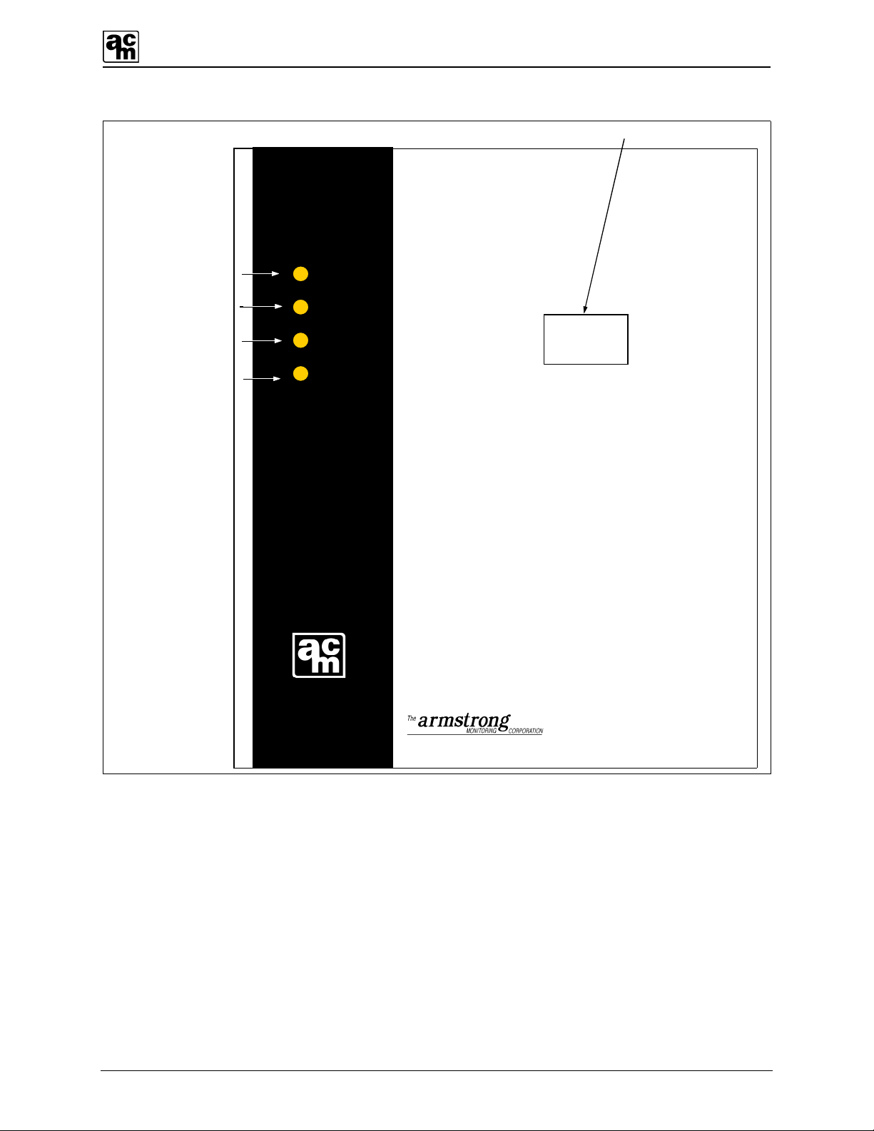
Information Section). The monitor comes with the following features (see Figures 1, 2 and 3).
1. POWER ON INDICATOR: Power is indicated by a green LED.
2. FAIL INDICATOR: Sensor fail is indicated by an amber LED.
3. LOW ALARM INDICATOR: Low levels of gas are indicated by a yellow LED.
4. HIGH ALARM INDICATOR: High levels of gas are indicated by a red LED.
5. POWER TERMINAL BLOCK: For line voltage connections (120 VAC, 60 Hz.)
6. TEST SWITCH: The test switch is provided to electronically simulate alarms
in order to test the low and high alarm indicators and relays.
7. LOW ALARM ADJUST: Sets the Low alarm trip point.
8. HIGH ALARM ADJUST: Sets the High alarm trip point.
9. THREE CIRCUIT MINIATURE
SWITCH:
Each actuator on the miniature switch controls a different
circuit as shown in Figure 1. If the actuator is set in the UP
position, its corresponding circuit is ON. If the actuator is
set in the DOWN position, the circuit is OFF.
9. a) TOP ACTUATOR: Provides a TEN-minute time delay, when the switch is ON,
to eliminate unnecessary alarms caused by momentary
exposure to high alarm conditions.
9. b) MIDDLE ACTUATOR: Provides a FIVE-minute time delay, when the switch is ON,
to eliminate unnecessary alarms caused by momentary
exposure to low alarm conditions.
9. c) BOTTOM ACTUATOR: Controls the audio alarm indicator. When ON, the buzzer
will activate when a high alarm condition occurs.
10. RELAYS:
There are up to 3 DPDT relays, which work with high alarm,
low alarm, and as an option fail.
11. TRANSFORMER:
Class II, step down transformer runs the internal circuitry at
low voltages.
12. NEMA 4X AUDIO ALARM: When enabled, the buzzer will activate when a high alarm
condition occurs.

AMC-1044-T Monitor
2
HI
LOW
TIME DELAYS
ON
THREE CIRCUIT
MINIATURE SWITCH
AUDIO ALARM
ACTUATORS
Figure 1: Three-circuit miniature switch.
AMC-1044-T Monitor
3
1044
215 Colonnade Road South Nepean, Ontario, K2E 7K3
U.S. & Canada toll free 1 (800) 4655777
-
1
) Power On Indicator
2
) Fail Indicator
3
) Low Alarm Indicator
4
) High Alarm Indicator
POWER
FAIL
LOW
HIGH
095
Display Optional
Figure 2: AMC-1044-T monitor, front panel.
AMC-1044-T Monitor
4
-FAIL+
TB6
TB2
HIGH
LOW
FAIL
POWER
AUD
DLY
L
H
-LO+
-HI+
GND AC AC
11.
GND NEUT. HOT
120 VAC
FUSE 1 A
10.
5.
8.
7.
9.
6.
HI
LOW
OPTIONAL
FAIL
12.
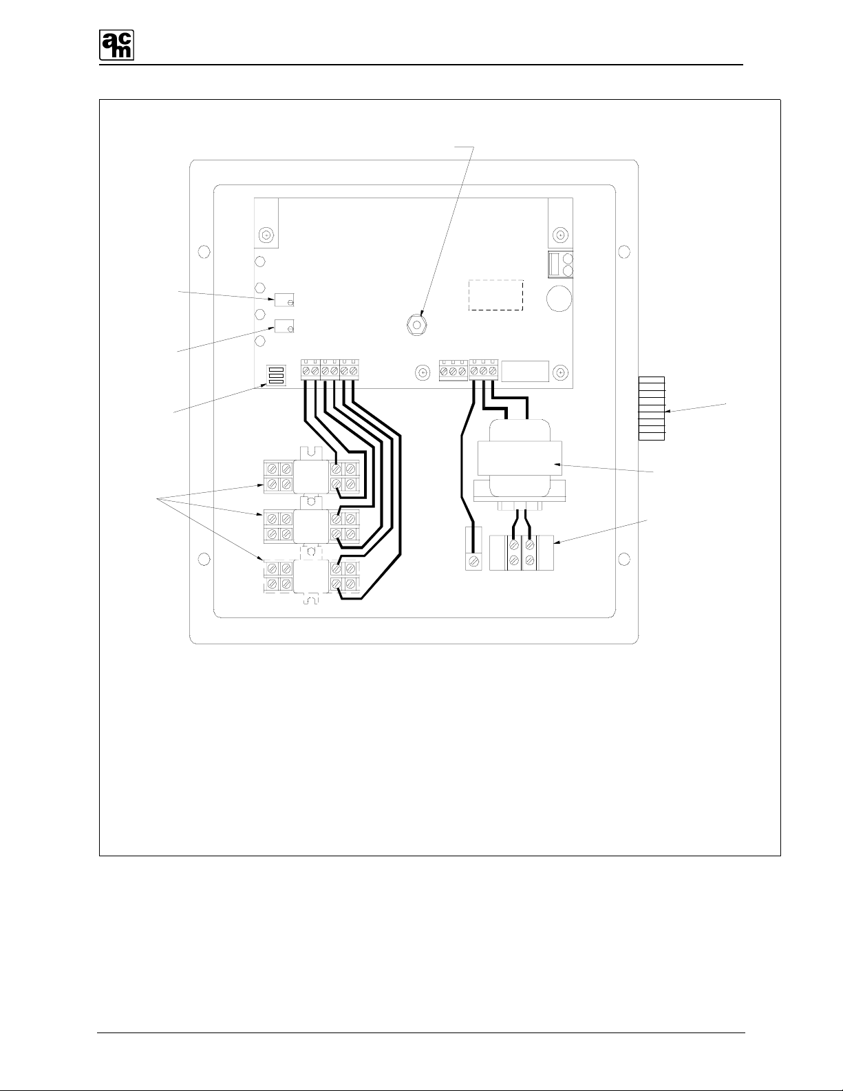
5. POWER TERMINAL BLOCK
6. TEST SWITCH
7. LOW ALARM ADJUST
8. HIGH ALARM ADJUST
9. THREE CIRCUIT MINIATURE SWITCH
10. RELAYS
11. TRANSFORMER
12. AUDIO ALARM
TB5
+ SIG –
Figure 3: AMC-1044-T monitor, internal wiring.

AMC-1044-T Monitor
5
4 INSTALLATION
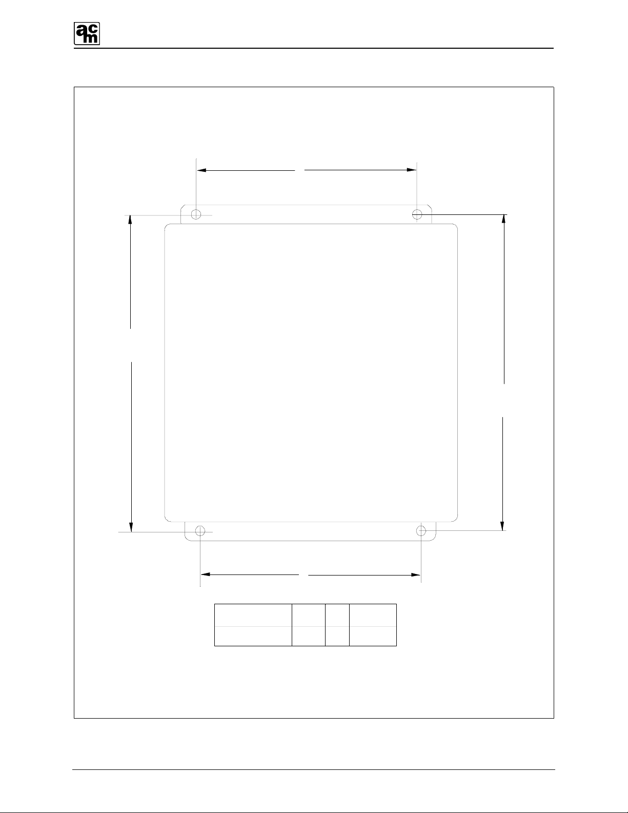
4.1 LOCATION AND MOUNTING
Care should be taken to securely fasten the AMC-1044-T monitor unit (via four mounting holes
provided) to a solid, vertical, non-vibrating surface or structure. Mounting height is dependent on
gas type. (See Figure 5 for mounting dimensions.)
Note:
All cable entry MUST be through the BOTTOM of the monitor enclosure only. Other
entry locations will allow foreign materials to enter the enclosure, possibly causing
damage to internal components. Mounting hardware and conduit connections are NOT
supplied.
Mount the 1044-T NEMA-4x monitor in a NON-HAZARDOUS area where local concentrations
of gases are unaffected by the presence of ventilation systems and where the unit can be
observed periodically.
4.2 WIRING OF THE MONITOR
POWER SUPPLY: The monitor operates on 120 VAC, 60 Hz. A Class II step down
transformer runs the internal circuitry at low voltages. The power supply
connections are made at the power terminal block located inside the
monitor. (See Figure 3)
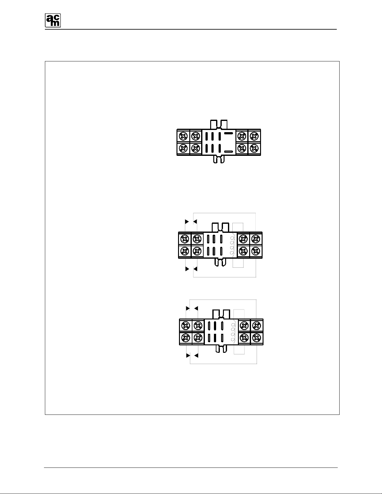
RELAYS: There are up to 3 DPDT relays, which activate with high alarm, low alarm
and optional fail respectively causing contact transfer. The contacts are
available for activating a remote alarm and/or, blower motors where
moving parts are fully guarded, pumps or lighting circuits. Relays are
rated 1/3 hp @ 120 VAC/240 VAC, 10 Amps @ 28 VDC/120 VAC/240
VAC resistive. For relay contact arrangement see Figure 6. The high and
low alarms relay coils are normally de-energized and the optional fail
relay coil is normally energized.
TRANSMITTER Each transmitter connects to a terminal block labeled Sensor (-SENS+)
located on the PC board. All Connections should be made using shielded
2 or 3-conductor cable, depending on which sensor or transmitter is
used. See schedule of cable sizes (Section 4.3) to select the appropriate
cable.
AMC-1044-T Monitor
6
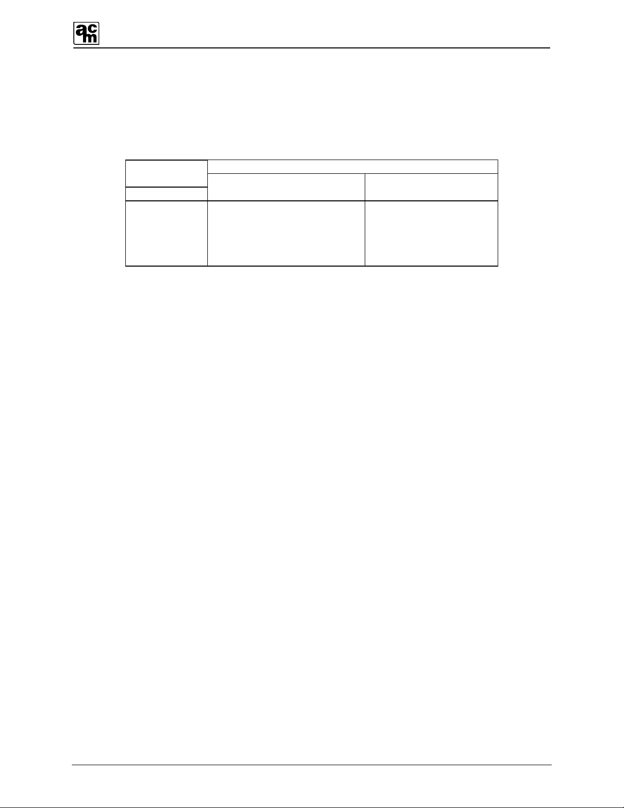
4.3 CABLE SIZES
For maximum noise rejection, each cable shield and metal conduit should be grounded at the
monitor. The following is a listing of maximum distances the transmitter may be located from the
monitor for various cable sizes.
CABLE LENGTH in FEET (meters)
WIRE
GAUGE
AWG 3-Wire Transmitter 2-Wire Transmitter
22 185 (56) 1000 (305)
20 290 (88) 1500 (457)
18 460 (141) 2500 (762)
16 700 (214) 3800 (1158)
14 1110 (338) 5600 (1706)

AMC-1044-T Monitor
7
-FAIL+ TB6
TB2
HIGH
LOW
FAIL
POWER
AUD
DLY
LH
-LO+
-HI+
GND AC AC
GND
NEUT. HOT
120 VAC
FUSE 1 A
HI
LOW
OPTIONAL
FAIL
TB5
+ SIG –
TRANSMITTER
+ S –
+ SENS -
For 2 - wire Sensor/Transmitters
+ SENS -
For 3 - wire Sensor/Transmitters
SIG SIG
FIGURE 4: Transmitter wiring connection
AMC-1044-T Monitor
8
10.75
6.0 4.0
DIMENSIONS
IN INCHES
A
B
DEPTH
B
A
B
A
Figure 5: Monitor mounting dimensions.
AMC-1044-T Monitor
9
RELAY
SOCKET
COM.
COIL
N.C.
N.O.
N.O. N.C.
COIL
COM.
RELAY SOCKET
CONNECTIONS
RELAY DE-ENERGIZED
75
31
86
42
COIL COM.
N.O. N.C.
RELAY ENERGIZED
BBB
AAA
86
42
COIL COM.
N.O. N.C.
75
31
Figure 6: Relay contacts wiring diagram.

AMC-1044-T Monitor
10
5 OPERATION AND CALIBRATION
5.1 OPERATION
Note:
BEFORE turning on the main power to the monitor, MAKE SURE all connections are
properly made.
Once power has been turned on, the GREEN power LED will light. A one-minute time delay
eliminates false alarms from occurring during the sensor’s warm up period. After this time
delay, the unit becomes fully operational. If time delays are required or the audio alarm
indicator is not needed, the three-circuit miniature switch can be set accordingly. Refer to
Section 3, Item 9 and Figure 1.
If any gas surrounding the sensor exceeds the low alarm trip point setting, the YELLOW LED
and low alarm relay will be activated. If any gas exceeds the high alarm trip point setting, the
RED LED, high alarm relay and audio alarm will be activated. An open sensor/transmitter circuit
is indicated by the amber fail LED.
5.2 CALIBRATION
The AMC-1044-T series monitor is factory calibrated at levels based on set standards.
As the calibration procedure may cause the monitoring equipment to give a false alarm,
appropriate precautions should be taken. Instructions on introducing the gas sample are
included with the sensor/transmitter manual. Refer to the transmitter manual for calibration and
required equipment.
NOTE
BEFORE MAKING ANY CHANGES TO ALARM LEVEL SETTINGS WE RECOMMEND
CONSULTING THE ARMSTRONG MONITORING CORPORATION FOR ADVICE ON SETTING THE
PROPER TRIP POINT VOLTAGE FOR A SPECIFIC ALARM CHANGE.
5.2.1 CALIBRATION FOR REMOTE SENSOR/TRANSMITTER
Please refer to applicable Sensor/Transmitter manual for calibration instructions.
5.2.2 ALARM ADJUSTMENTS FOR TRANSMITTER
Alarms are set at the factory and do not need to be adjusted unless a change in alarms is
required.
Low alarm adjust is used to establish the low alarm trip point. This is done by adjusting the
voltage to the appropriate fraction of full scale at test points COM and LOW TP (see Figure 7).

AMC-1044-T Monitor
11
Example: Full scale = 100 ppm
Low alarm trip = 35 ppm
(35/100 x 4 VDC)+1
= 2.4 VDC
High alarm adjustment is done in the same manner as above, using the high alarm adjust and
measuring between COM and HIGH TP.
-FAIL+
TB6
TB2
HIGH LED
LOW LED
FAIL LED
POWER LED
AUD
DLY
L
H
-LO+
-HI+
GND AC AC
FUSE
+-
MULTIMETER
DIGITAL
SIG
TP
COM
TP
LOW ALARM
ADJUST
HIGH ALARM
ADJUST
LOW
HI
TP
Figure 7: Alarm adjustments

AMC-1044-T Monitor
12
6 PREVENTIVE MAINTENANCE
6.1 GENERAL
The monitor should be wiped clean with a damp cloth following a regular maintenance program.
Avoid spraying, submersion and other conditions that could cause a liquid to enter the monitor
and cause possible intrinsic damage to internal components.
This manual suits for next models
1
Table of contents


