506860-01Issue 1404Page 6 of 35
Placement
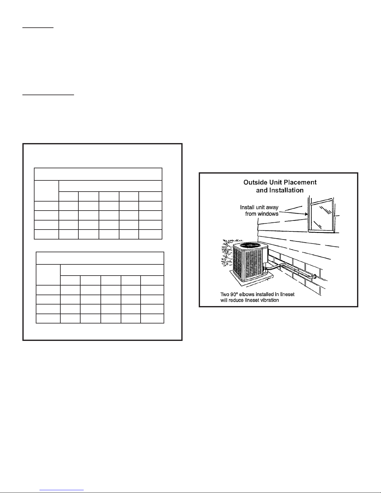
Be aware that some localities are adopting sound ordinances
based on how noisy the unit is at the neighbor’s home, not
at the original installation. Install the unit as far as possible
from the property line. When possible, do not install the unit
directly outside a bedroom window. Glass has a very high
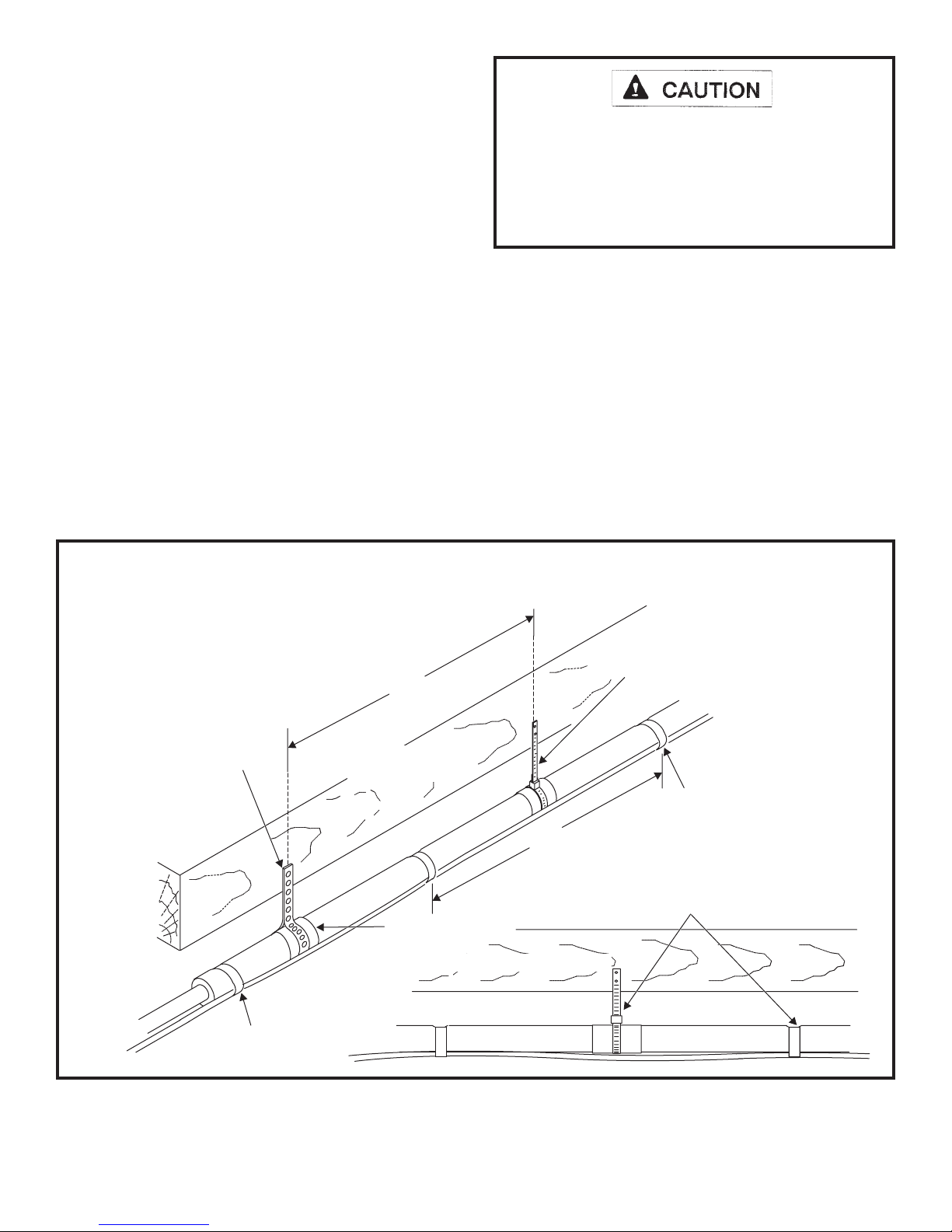
level of sound transmission. Figure 7 shows how to place
the outdoor unit and line set to reduce line set vibration.
Line Set Isolation
Illustrations on pages 7 and 8 demonstrate procedures which
ensure proper refrigerant line set isolation. Figure 8 shows
how to install line sets on horizontal runs. Figure 9 shows
how to make a transition from horizontal to vertical. Figure
10 shows how to install line sets on vertical runs.
4. Remove the Schrader core assemblies before brazing
to protect them from damage due to extreme heat.
Replace the cores when brazing is complete.
5. Remove light maroon washers from service valves
and shield light maroon stickers to protect them during
brazing. Wrap a wet cloth around the valve body and
copper tube stub to protect it from heat damage.
6. Braze the line set to the service valve. Quench the
joints with water or a wet cloth to prevent heat damage
to the valve core and opening port. The tube end must
stay bottomed in the tting during nal assembly
to ensure proper seating, sealing, and rigidity.
7. Install the thermal expansion valve which is sold
separately and which is approved for use with R410A
refrigerant in the liquid line at the indoor coil (see
Refrigerant Metering Device on page 10).
Brazing Connection Procedure
1. Cut ends of refrigerant lines square (free from nicks or
dents). Debur the ends. The pipe must remain round;
do not pinch end of line.
2. Before making line set connections, use dry nitrogen to
purge the refrigerant piping. This will help to prevent
oxidation and the introduction of moisture into the
system.
3. Use silver alloy brazing rods (5% or 6% silver alloy for
copper-to-copper brazing or 45% silver alloy for copper-
to-brass or copper-to-steel brazing) which are rated for
use with R410A refrigerant.
Refrigerant Piping
If the 4SHP16/18LS unit is being installed with a new indoor
coil and line set, the refrigerant connections should be made
as outlined in this section. If an existing line set and/or
indoor coil will be used to complete the system, refer to this
section as well as the section that follows entitled- Flushing
Existing Line Set and Indoor Coil.
If this unit is being matched with an approved line set
or indoor coil which was previously charged with R-22
refrigerant, the line set and coil must be ushed prior to
installation. If the unit is being used with and existing indoor
coil which was equipped with a liquid line which served as
a metering device (RFCI), the liquid line must be replaced
prior to the installation of the 4SHP16/18LS unit.
Field refrigerant piping consists of liquid and suction lines
from the outdoor unit (sweat connections) to the indoor
Figure 7
Table 2
Refrigerant Line Set Diameters (in.)
For installations exceeding 50’, contact Technical Services.
Liquid Line
BTUH Line Set Length and Size
12 ft. 25 ft. 50 ft. 75 ft. 100 ft.
24,000 3/8 3/8 3/8 3/8 3/8
36,000 3/8 3/8 3/8 3/8 1/2
48,000 3/8 3/8 3/8 1/2 1/2
60,000 3/8 3/8 3/8 1/2 1/2
Suction Line
BTUH Line Set Length and Size
12 ft. 25 ft. 50 ft. 75 ft. 100 ft.
24,000 3/4 7/8 3/4 7/8 7/8
36,000 7/8 7/8 7/8 7/8 1-1/8
48,000 1-1/8 1-1/8 1-1/8 1-1/8 1-1/8
60,000 1-1/8 1-1/8 1-1/8 1-1/8 1-1/8