6www.armstrongfluidtechnology.com
L4 L2
L3
L1
G
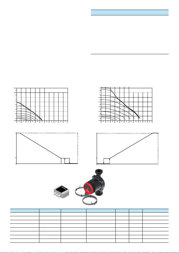
technical data
Rate of flow: up to 3.8 m3/h
Pressure head: 4 m/7 m
Control range: 4-25 W/4-70 W
Mediumtemperature:+2 °C to +110 °C
Installation length: 130 and 180 mm
Threaded connection:1“, 1½“ and 2“
Protection class: IP 42
Insulation class: F
Control: PWM1 (heating) and
PWM2 (solar, inverted)
flow medium
• heating water as per VDI 2035
• pure, thin, non-aggressive and non-explosive,
mineral oil-free medium without solid or long-
fibre components
• medium with a max. viscosity of 10 mm2/s
• operating data must be checked above 20% glycol
materials
component material material no.
Pump housing Grey-cast iron 0.6020
Impeller Polyamide (PA - GF 35)
Shaft Ceramic
Bearing Ceramic
Bearing plate Stainless steel 1.4301
Can Stainless steel 1.4301
product features
• compact design
• manual start-up
feature
• smooth running
• very low energy
consumption
• starting current limit
(softstart)
• air-vent screw
• pre-mounted cable
(1 m)*
• space-saving axially
integrated terminal box
• control input
switchable from
PWM1 to PWM2
* other cable lengths on request
temperature range
Ambient temperature: 0 °C to +40 °C
Temperature class: TF 110
Media temperature: +2 °C to +110 °C
To avoid condensation forming in the terminal box
and stator, the media temperature must always be
the same or higher than the ambient temperature.
ambient temp. media temp. min. media temp. max.
0 2 110
10 10 110
20 20 110
30 30 95
35 35 90
40 40 90
motor protection
The motor winding is designed to be blocking
current-proof. Therefore motor protection is not
required.
minimum inflow pressure
Please determine the minimum inflow pressure
for corresponding temperature from the following
table.
Media temperature < 75 °C > 90 °C
Minimum inflow pressure 0,05 bar 0,28 bar
casing pressure
10 bar
sound pressure level
The sound pressure level is < 45 dB (A).
dimensions
typ l1 l2 l3 l4
hep pwm 130/180 98 127 163
dimension illustration
ECM
Technology
technical data pump: