Armstrong TRI-PAK TR-230 User manual

Installation Manual
TRI-PAK™ TR-230
CEILING SYSTEMS

Make all wiring connections prior to
AC connection and power up.
WARNING:
To reduce the risk of fire or electric
shock, do not expose this apparatus to
rain or moisture.
Apparatus shall not be exposed to
dripping or splashing and no objects
filled with liquids, such as vases, shall
be placed on the apparatus.
WARNING FOR YOUR PROTECTION
PLEASE READ THE FOLLOWING:
1) Read these instructions.
2) Keep these instructions.
3) Heed all warnings.
4) Follow all instructions.
5) Do not use this apparatus near water.
6) Clean only with dry cloth.
7) Do not block any ventilation openings. Install in
accordance with the manufacturer’s instructions.
8) Do not install near any heat sources such as
radiators, heat registers, stoves, or other
apparatus (including amplifiers) that produce heat.
9) Do not defeat the safety purpose of the polarized
or grounding-type plug. A polarized plug has two
blades with one wider than the other. A grounding
type plug has two blades and a third grounding
prong. The wide blade or the third prong are
provided for your safety. If the provided plug does
not fit into your outlet, consult an electrician for
replacement of the obsolete outlet.
10) Protect the power cord from being walked on
or pinched particularly at plugs, convenience
receptacles, and the point where they exit from
the apparatus.
11) Only use attachments/accessories specified by
the manufacturer.
12) Use only with the cart, stand, tripod, bracket, or
table specified by the manufacturer, or sold with
the apparatus. When a cart is used, use caution
when moving the cart/apparatus combination to
avoid injury from tip-over.
13) Unplug this apparatus during lightning storms
or when unused for long periods of time.
14) Refer all servicing to qualified service personnel.
Servicing is required when the apparatus has been
damaged in any way, such as power-supply cord
or plug is damaged, liquid has been spilled or
objects have fallen into the apparatus, the
apparatus has been exposed to rain or moisture,
does not operate normally, or has been dropped.
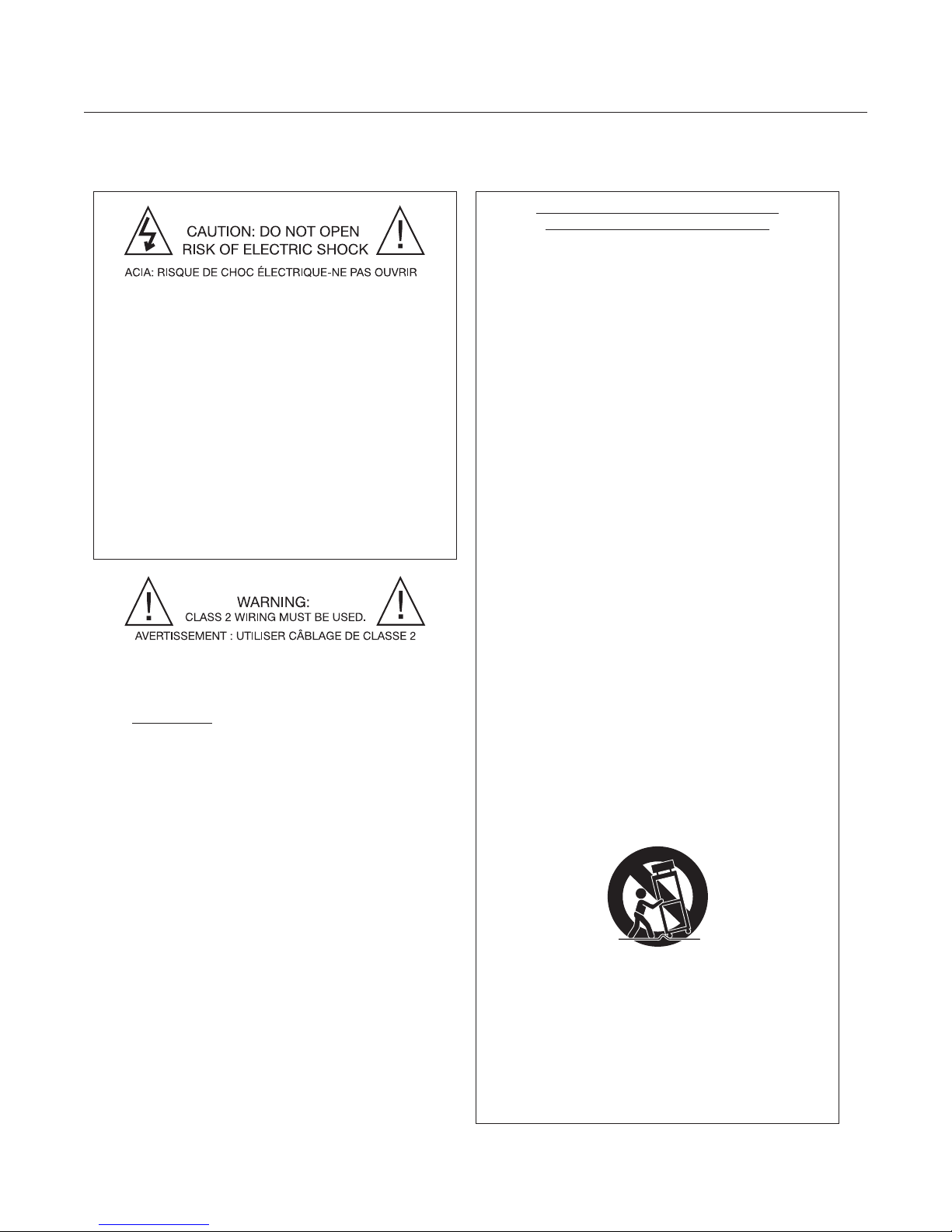
The symbols shown above are internationally accepted
symbols that warn of potential hazards with electrical
products. The lighting flash with arrow point in an
equilateral triangle means that there are dangerous
voltages present within these units. The exclamation
point in an equilateral triangle indicates that it is
necessary for the user to refer to the owner’s manual.
These symbols warn that there are no user serviceable
parts inside these units. Do not open these units. do not
attempt to service the unit yourself. Refer all servicing
to qualified personnel. Opening the chassis for any
reason will void the manufacturer’s warranty. Do not
get the unit wet. If liquid is spilled on the unit, shut it
off immediately and take it to a dealer for service.
Disconnect the unit during storms to prevent damage.
IMPORTANT SAFETY INSTRUCTIONS
TR-230 Installation Manual - Page i

SECTION: PAGE:
1. Introduction ............................................................................................1
2. Block Diagram and Panel Descriptions .................................................2
3. Truth Tables and Factory Default Settings.............................................6
4. Installation and Mounting Options.........................................................7
5. Application Guides.................................................................................9
A. Quick Start ..................................................................................9
B. Sound Masking..........................................................................11
C. Paging:.......................................................................................14
– Via Telephone .........................................................................14
– Page Expansion .....................................................................18
– Via Microphone ......................................................................19
– Talkback .................................................................................21
D. Music / Line Level......................................................................22
E. AHJ / Mute All ............................................................................24
6. Technical Specifications........................................................................25
7. Troubleshooting Guide..........................................................................26
8. Glossary of Terms .................................................................................27
9. Warranty Information.............................................................................28
TABLE OF CONTENTS
TR-230 Installation Manual - Page ii

1.1 CHECK CONTENTS Read and verify the following list of TR-230 carton contents:
•(1) TR-230 electronics unit
•(1) Installation Manual
•(1) 2-pin terminal block plug (for AHJ)
•(4) 3-pin terminal block plugs (for page and balanced line out)
•(2) large 3-pin terminal block plugs (for speaker outputs)
•(2) small 4-pin terminal block plugs (for output voltage select)
•(1) 4-pin terminal block plug (for phone system input)
•(2) 5-pin terminal block plugs (for music/line inputs)
•(1) AC power cord
•(2) ears for optional rack mounting
•(1) metal “E” bracket for optional vertical or horizontal wall mounting
•(4) rubber, stick-on feet for shelf mounting
Read the following electrical and mechanical requirements for your
i-ceilings system components.
Mains power: 100 – 240 VAC, 50-60 Hz
Maximum Power Consumption: 85 W
Fuse: 1 Amp, Fast Acting
Dimensions: 1.75"(h) x 19"(w) x 8.5"(d)
Weight: 8 Lbs.
Ambient Temperature*: < 86º F (30ºC)
Storage Temperature: 0º - 50º C (32º-122º F)
*Mounted in EIA rack with 1RU panel space above and below unit
Read all sections related to circuit description, installation guide and
panel descriptions to gain a complete understanding of all inputs, outputs
and switches prior to installation.
The following tools may be helpful for proper installation of this unit:
•Flat / Phillips blade screwdriver
•Wire strippers (16 AWG to 24 AWG)
•Multimeter
•Telephone test set (for paging applications)
•Portable 25V/70V/100V speaker
•SPL meter
SECTION 1: INTRODUCTION
The TRI-PAK™ TR-230 is a high quality, two
channel digital audio system delivering any
combination of music, paging, and sound
masking applications – either as two separate
zones or as a single 2-channel zone – into
commercial buildings.
The DSP-based unit delivers two 30 watt channels
to selectable outputs at 25 volt, 70 volt, or 100
volt. Two uncorrelated, on-board digital noise
generators provide masking signals at either -4 dB
per octave or NC40 via switch selection. A
comprehensive telephone paging interface for local
and remote access is provided with optional talk-
back. Multiple line/music level inputs are provided.
Switch selectable equalization for room effects and
Armstrong P-25 and E-5 speakers is also built in.
When you need more than two channels of paging
or music, two balanced line outputs for system
expansion of the primary TR-230 are included.
The TR-230 is compatible with the Armstrong
A2001 and D2001 digital signal processors (the
TR-230 can drive either unit, but can be a down-
stream unit for only the A2001 model), as well as
with other commercial audio systems (speakers
and electronics).
1.2 CHECK MECHANICAL
AND ELECTRICAL
REQUIREMENTS
Electrical:
Mechanical:
1.3 FAMILIARIZE
YOURSELF WITH
THIS EQUIPMENT
1.4 USEFUL TOOLS
TR-230 Installation Manual - Page 1

SECTION 2: BLOCK DIAGRAM AND PANEL DESCRIPTIONS
HYBRID
MUTE/DUCK
CONTROL
MUTE/DUCK
CONTROL
TEST
TONES
TALKBACK
MASKING
GENERATOR
MASKING
FILTER
SPEAKER
EQ
SPACE
EQ
'AHJ'
MUTE
ALL
MASKING
GENERATOR
MASKING
FILTER
SPEAKER
EQ
SPACE
EQ
MASKING
LEVEL
CONTROL
MASKING
LEVEL
CONTROL
PAGING
LEVEL
CONTROL PAGING
LEVEL
CONTROL
MUSIC
LEVEL
CONTROL
MUSIC
LEVEL
CONTROL
ZONE 1
SPEAKER
OUTPUT
ZONE 2
SPEAKER
OUTPUT
J14
J12
J6
PAGE
CONTACT
CLOSURE
J5
PAGE BAL
LINE
OUTPUT
J10
MUSIC -
LINE 1
BAL LINE
OUTPUT
MUSIC -
LINE 2
BAL LINE
OUTPUT
J8
VOLTAGE
SELECTION
[ 25V, 70V, 100V ]
VOLTAGE
SELECTION
[ 25V, 70V, 100V ]
J13
J11
J2
TELCO
INPUT
J3 / J4
(SW2)
SW 3
ZONE 2
ZONE 1
MUSIC /
LINE 1
MUSIC /
LINE 2
J9
J7
FRONT PANEL:
BLOCK DIAGRAM:
REAR PANEL:
TR-230 Installation Manual - Page 2

SECTION 2: FRONT PANEL
POWER LED:
“Green” indicates
power is on.
PAGE STATUS LED’s:
RELAY ENABLED: “Amber” indicates
relay input contact is activated when
page is enabled.
SIGNAL: “Green” indicates presence
of telephone or microphone signal.
0 dB: “Amber” indicates signal level
has reached 0 dBu.
ZONE 1 AND ZONE 2:
MASKING VOLUME: Tamper-proof
recessed volume control to set
appropriate signal level. Use small
flat head screwdriver.
PAGING VOLUME: Page volume
control via accessible knob to adjust
paging volume in each zone.
MUSIC VOLUME: Music volume
control via accessible knob to adjust
background music volume in each zone.
MUSIC LED: “Green” indicates music
signal is present.
AMP OVERLOAD LED:
“Red” indicates
amp is clipping.
TR-230 Installation Manual - Page 3

TR-230 Installation Manual - Page 4
SECTION 2: REAR PANEL
AC POWER [J1]:
AC input connection with
on/off switch [SW1]
AHJ INPUT [J2]:
Authority Having
Jurisdiction for local fire
authority requirements to
mute all audio [no polarity].
TELEPHONE SYSTEM INPUT [J3]:
Terminal block for discrete
connection of telephone input with
Normally Open [NO], Common [C],
tip [-] and ring [+] terminations.
TELEPHONE SYSTEM
INPUT/SELECT [SW2]:
Manual slide switch for
selection of J3 terminal
block or RJ11 termination
of phone system page
input.
TELEPHONE SYSTEM
INPUT [J4]:
RJ11 connector
TELEPHONE SYSTEM PAGE
INPUT/SELECT [SW3]:
Manual slide switch for selection of
telephone line type: VoIP (Voice over
Internet Protocol), DL (Dry Loop), and
SA (Station Access and Centrex); or
LS (Loop Start).
PAGE OUT [J5 AND J6]:
Audio signal [J5] and relay [J6] for
extension to auxiliary paging equipment.
This is for voice telephone page and DTMF
output only and will not pass masking or
music signals to a secondary unit.

S_+
TR-230 Installation Manual - Page 5
SECTION 2: REAR PANEL
MUSIC / LINE [J7 and J9]:
Music, line level, and line level
microphone input.
Note: Music will automatically
sum to speaker zones 1 and 2
with DIP position 3 up on SW6.
(See Figure 12 on page 23.)
ZONE SETUP OPTIONS
[SW4 and SW5]:
Individual setup options
for zones 1 and 2. See
section 3 for truth table.
BALANCED LINE
OUTPUTS [J8 and J10]:
Voice page and music
line level output to
auxiliary amplifiers and
processors.
NOTE: Masking signal
and all EQ options will
not pass. (See block dia-
gram for further details.)
COMMON SETUP
OPTIONS [SW6]:
Feature options
common to
zones 1 and 2.
See section 3 for
truth table.
SPEAKER ZONES 1
AND 2 [J12 and J14]:
Power output to
speakers @ 25V, 70V
or 100V.
SPEAKER WIRING
[J12 and J14]:
Flat Blade
Screwdriver
Wire conductors –
strip back jacket
1/4" to 1/2" –
insert bare copper
conductor into slot –
tighten with screw.
COM 25V 70V
100V
COM
70V
JUMPER WIRE
FACTORY PRESET @ 70V
NOTE:
Depress center spring actuator
(orange) to insert wire loop.
CAUTION:
VOLTAGE SELECT IS NOT
A SPEAKER OUTPUT - DO
NOT CONNECT SPEAKERS
TO J11 OR J13 !
VOLTAGE SELECT [J11 and J13]:
Connector/wire jumper selection
of voltage @ 25V, 70V or 100V.

SECTION 3: TRUTH TABLES AND FACTORY DEFAULT SETTINGS
ZONE 1 AND 2 SETUP OPTIONS:
Factory Default Settings: (DIP Switches 1-8 all down)
•Masking off
•Normal space EQ
•No speaker EQ
•Duck music on page
•Talkback off
NOTE: Do not select the up position on both 5 and 6.
This setting is for a different speaker EQ specific to an
Armstrong product available outside of North America.
COMMON SETUP OPTIONS:
Factory Default Settings: (DIP Switches 1-4 all down)
•-4dB noise source filter (masking signal)
•10 second Station Access paging timeout
•Normal line inputs
•Test tone off
OTHER FACTORY DEFAULTS:
Speaker zone 1 and 2 voltage selection is factory set at 70V.
HOW TO SELECT OPTIONS USING THE DIP SWITCHES:
The zone and common setup options are selected via DIP switches which
can be accessed with a small screwdriver. In the truth tables, “on” means
“up,” and “off” means “down.”
Switch Number
1234567 8
Off Masking "Off"
On Masking "On"
Off Off Off Normal Space Equalization
Off Off On -1.5 dB Space Equalization
On Off On -3.0 dB S
p
ace E
q
ualization
Off On On +1.5 dB Space Equalization
On On On +3.0 dB Space Equalization
Off Off No Speaker EQ
On Off E-5 Speaker EQ
Off On P-25 Speaker EQ
On Muting of music on page
Off 20 dB Ducking of music on page
Off Talkback "Off"
On Talkback "On"
ZONE SETUP OPTIONS
COMMON SETUP OPTIONS
Switch Number
1234
Off -4dB noise source filter
On NC40 noise source filter
Off 10 Second Station Access paging timeout
On 5 Second Station Access paging timeout
Off Normal Line Inputs 1 and 2
On Sum Line Inputs 1 and 2
Off Test Tone Off
On Test Tone On
Up
On
Down
Off
TR-230 Installation Manual - Page 6

SECTION 4: INSTALLATION AND MOUNTING OPTIONS
MOVE BRACKETS (1) SPACE TOWARD
REAR, SECURE (2) SCREWS
ROTATE BRACKETS 180 DEGREES
TOWARD REAR, SECURE (4) SCREWS
ROTATE BRACKETS TOWARD
REAR, SECURE (2) SCREWS
TR-230 SIDE VIEW
3"
2"
1"
1"
MOVE BRACKETS TOWARD
FRONT, SECURE (2) SCREWS
RACK OR CABINET MOUNTING OPTIONS:
Use the two adjustable mounting brackets for the following
mounting options in racks or cabinets:
FLUSH WITH FRONT
CABINET RAIL
(as shown in photo above
and diagram to the left)
FRONT PANEL IS
FORWARD 1" IN RACK
FRONT PANEL IS
FORWARD 2" IN RACK
FRONT PANEL IS
FORWARD 3" IN RACK
FRONT PANEL IS
BACK 1" IN RACK
1
2
3
4
5
TR-230 Installation Manual - Page 7

WALL SURFACE
Zone 1 Zone 2
4b4a
HORIZONTAL WALL
MOUNT
(pictured to left)
VERTICAL WALL
MOUNT
(pictured to right)
UTILIZING THE "E" STABILIZING
BRACKET
TR-230
TR-230
TR-230
1.250" AIR SPACE
FROM WALL
WALL SURFACE
2
3
3
SECTION 4: INSTALLATION AND MOUNTING OPTIONS
WALL MOUNTING OPTIONS:
Rotate mounting brackets toward top of unit.
Secure with two screws on each side. NOTE: This provides 1.25" of air ventilation space from the wall surface and
facilitates ease of reading front panel controls.
Secure stabilizing “E” bracket to wall with single screw and fit TR-230 in either vertical or horizontal mode.
Secure side mounting brackets to wall — either horizontally (a) or vertically (b) — with two screws per side.
1
2
3
4
1
TR-230 Installation Manual - Page 8

SECTION 5A: QUICK START APPLICATION GUIDE
5A. QUICK START
5A.1. SOUND MASKING ONLY
Step 1: Turn down masking volume controls on front panel full counter clockwise
with small flathead screwdriver.
Step 2: Make following DIP switch selections on SW4, SW5 and SW6 on rear panel:
•Select “masking on” by putting DIP switch 1 up in SW4 and SW5.
•Select a noise type (–4dB or NC40) on position 1 of SW6.
•Select appropriate speaker type on positions 5 and 6 of SW4 and
SW5 (P-25, E-5, or flat).
Step 3: Wire and connect speakers to appropriate zones in J12 and J14 connectors.
NOTE: The Factory Default is 70V output.
Step 4: Plug in AC power to J1 and turn power SW1 switch to “on” position. Verify that power
LED on front panel is green.
Step 5: Slowly turn up masking volume controls to appropriate level – listen for noise and
measure the level as required. NOTE: Masking levels are typically in the range of
42-43 dBA SPL in closed plan spaces and 47-48 dBA SPL in open plan spaces.
5A.2. PAGING ONLY
Step 1: Turn down paging volume controls on front panel full counter clockwise.
Step 2: Make following DIP switch selections on SW4, SW5 and SW6 on rear panel:
•Select appropriate speaker type in positions 5 and 6 of SW4 and SW5.
•Place Test Tone on via position 4 of SW6.
Step 3: Select the device for Paging Input (Telephone or Amplified Microphone)
and make the following selections and connections:
TELEPHONE (see pages 16-17 for diagrams):
•Select the telephone system line type (Station Access, Centrex, VoIP,
Loop Start, Dry Loop) on SW3.
•Select connection type RJ11 (J4) or terminal block (J3) on SW2.
•Connect telephone line to J3 or J4.
AMPLIFIED MICROPHONE (see pages 19-20 for diagrams):
•Select terminal block J3 position on SW2.
•Wire to J3 with 2 pair/ 4 wire as indicated (NO=Normally open, C=Common, + and -).
Step 4: Wire and connect speakers to appropriate zones on J12 and J14.
Step 5: Plug in AC Power to J1 and turn SW1 on. Verify power LED is green.
Step 6: You should now hear the on-board test tone. Remove test tone from SW6, position 4
(turn switch down to “off”). Initiate page from telephone (Digits 1, 2 or 3 for Zone 1, 2,
or All-Call) or Microphone. Slowly turn up Paging volume controls for each zone.
TR-230 Installation Manual - Page 9

SECTION 5A: QUICK START APPLICATION GUIDE
5A.3. MUSIC ONLY
Step 1: Turn down music volume controls on front panel full counter clockwise.
Step 2: Make following DIP switch selection on SW4, SW5 and SW6 on rear panel:
•Select appropriate speaker type on positions 5 and 6 of SW4 and SW5.
Step 3: Connect music source to Music/Line inputs connectors on J7 and J10. Wire
as follows: Shield to -, Positive to + terminals.
NOTE: The TR-230 automatically sums Stereo input, to Mono for each channel. Wire
the – and + leads to the respective L and R terminals in the J7 and J10 positions.
Step 4: Wire and connect speakers to appropriate zones on J12 and J14.
Step 5: Plug in AC power to J1 and turn SW1 up to on. Verify power LED is green.
Step 6: Slowly turn up music volume control for each zone.
5A.4. COMBINED APPLICATIONS (MUSIC, PAGING AND MASKING)
Each application is independently controlled and can be implemented in any combination, such as:
1) paging and masking
2) music and masking
3) paging and music
4) music, paging and masking
To set up these combined applications, follow the appropriate directions above for each single
application. As you go from one application to the next, you will not need to re-select the
“speaker type” options already chosen.
TR-230 Installation Manual - Page 10

SECTION 5B: SOUND MASKING APPLICATION GUIDE
The TR-230 provides Sound Masking via two uncorrelated built-in noise generators and
includes a choice of two pre-filtered noise signals – the industry recognized NC40 or a - 4 dB
per octave spectra. Additionally, both speaker response EQs and space effect EQs are provided
to simplify the process of achieving speech privacy with a non-intrusive masking sound of
good tonal quality.
5B.1. APPLICATION LAYOUTS:
This unit can be used to supply any of the following masking applications:
1) Two uncorrelated masking signals in a single architectural zone for open plan masking
using an A and B speaker layout. (NOTE: This layout gives the best level of uniformity
throughout the installed space.)
2) Two separate masking signals in two separate architectural zones for closed plan masking
(NOTE: This layout is often used for dissimilar closed room sizes and/or surface treatments,
such as for offices and conference rooms separately.)
3) Two separate masking signals in two separate architectural zones for a closed plan and an
open plan. (NOTE: Open plan performance will not be as good as achieved in Figure 1
above, since only one signal is used throughout the open space.)
A
B A A
AB
B
B
ZONE 1
ZONE 2
NOTE: A-B masking as depicted above will result in a single zone pag-
ing system accessed by DTMF code 3 for an ‘ALL CALL PAGE’
OPEN PLAN
SPACE
ZONE 1
ZONE 2
A
B B B
AA
B
A
CLOSED
OFFICE PLAN
FIGURE 1 2 Channel Zone for Open Plan
FIGURE 2 2 Separate Zones for 2 Types
of Closed Plan
CONFERENCE
ROOM PLAN
ZONE 1
ZONE 2
A
B B B
AA
B
A
CLOSED
OFFICE PLAN
FIGURE 3 2 Separate Zones for
Open and Closed Plan
OPEN
OFFICE PLAN
TR-230 Installation Manual - Page 11

SECTION 5B: SOUND MASKING APPLICATION GUIDE
5B.2. FACTORY DEFAULT SETTINGS
The factory default settings for sound masking are the same for both speaker outputs, which
are labeled Zone 1 and Zone 2 on page 5. These default settings (as listed in page 6 for SW4,
SW5, and SW6) are as follows:
• Masking sound OFF
• No speaker EQ
• Normal space EQ
• - 4 dB per octave noise pre-filter
5B.3. OPEN PLAN SET-UP PROCEDURE
For an open plan application, it is usually recommended to use two uncorrelated masking
signals in a single architectural zone with the P-25 model i-ceilings®speaker in an A and B
speaker layout pattern. The set-up process is as follows:
1) Install P-25 speakers according to Figure 1, alternating A and B in a square or
diamond pattern.
2) Turn the masking volume down on the front panel for both zones. It takes a small flat
bladed screwdriver to adjust the tamper-proof control.
3) Turn on masking signal with DIP switch 1 on SW4 and SW5, where “up” means
masking is on.
4) Set the desired masking signal with DIP switch 1 on SW6. “Down” is for the – 4 dB
noise signal and “up” is for the NC40 noise signal.
5) Set the speaker EQ for the P-25 with DIP switches 5 & 6 on SW4 and SW5, where the
combination of 5 “down” and 6 “up” is for the P-25 speaker. (This setting provides an
inverse P-25 frequency response thus making the system flat relative to the speaker.)
6) Leave the space effects EQ at the default setting (normal) since an open plan space proba-
bly has low space effects due to the sound at the listener being primarily direct sound from
the speakers.
7) Turn the masking volume up on the front panel for both zones, being careful to have the
same level on each zone. Using a sound level meter (SLM), measure the sound in a cubicle
or occupant seating area, adjusting the level until the masking is approximately 48 dBA.
Repeat this measurement under a few A speakers and B speakers to ensure that each zone
is set at the same level.
8) You may choose to switch the space effect EQ to +1.5 to -1.5 or adjust the masking signal
to sound most pleasant or balanced to your ear. If either of these settings are chosen, you
will need to recheck the level in several occupant spaces and readjust the level to 48 dBA.
TR-230 Installation Manual - Page 12

SECTION 5B: SOUND MASKING APPLICATION GUIDE
5B.4. CLOSED PLAN SET-UP PROCEDURE
For a closed plan application, it is usually recommended to use a single masking signal in a
single architectural zone with the P-25 model i-ceilings speaker installed (one to a room for
rooms up to 20' x 20'). NOTE: For larger rooms, where four or more P-25 speakers may be
needed, it may be appropriate to use a 2 channel, 1 zone layout instead.
The set-up process for typical closed plan applications is as follows:
1) Install P-25 speakers according to Figure 2.
2) Turn the masking volume down on the front panel for both zones. It takes a small flat
bladed screw driver to adjust the tamper proof control.
3) Turn on masking signal with DIP switch 1 on SW4 and SW5, where “up” means
masking is on.
4) Set the desired masking signal with DIP switch 1 on SW6. “Down” is for the – 4 dB noise
signal and “up” is for the NC40 noise signal
5) Set the speaker EQ for the P-25 with DIP switches 5 & 6 on SW4 and SW5, where the com-
bination of 5 “down” and 6 “up” is for the P-25 speaker. (This setting provides an inverse
P-25 frequency response thus making the system flat relative to the speaker.)
6) Set the space effect EQ with DIP switches 2, 3, 4 on SW4 and SW5, where the settings are
listed in the truth tables on page 6, for each zone separately. Choose the settings as follows:
• Normal: average sized room furnished in an average way [10x10x9 ft, standard
acoustical ceiling (NRC .60), standard commercial grade carpet]
• + 3 dB: large room furnished with lots of sound treatment [20x20x9 ft,
high-performance ceiling (NRC .75), fiberglass wall panels (NRC .85) on 2 walls,
standard commercial grade carpet]
• +1.5 dB: large room furnished with some sound treatment [16x16x9 ft,
standard acoustical ceiling (NRC .65), Mineral fiber wall panels (NRC .50) on one
wall, standard commercial grade carpet]
• – 1.5 dB: small room furnished with little sound treatment [8x8x9 ft,
standard acoustical ceiling (NRC .50), no wall treatment, standard commercial
grade carpet]
• – 3.0 dB: small room with no sound treatment [8x8x9 ft, drywall surfaces, thin carpet]
7) Turn the masking volume up on the front panel for each zone separately. Using a sound level
meter (SLM), measure the sound at an occupant seating area, adjusting the level until the
masking is approximately 43 dBA. Repeat this measurement in a couple locations to ensure
that each zone is set properly.
5B.5. MIXED PLAN SET
-UP PROCEDURE
Follow the previous procedures, using only one zone for the open plan and one for
the closed plan, according to Figure 3.
TR-230 Installation Manual - Page 13

The TR-230 provides two independent 30 watt zone outputs for voice paging.
Paging is accomplished using telephone and/or microphone sources with the following options:
•Single zone or All-Call paging
•Duck or mute music during page
•Hands-free talkback
•DTMF decoding for zone page access
Paging can be provided over both music and masking.
Page expansion is accomplished via a balanced line output per zone for stacking additional
TR-230 systems, auxiliary paging equipment and amplifiers. Remote OPX (off-premise extension)
paging via the Public Switched Telephone Network (PSTN) is achieved via the balanced paging
output.
5C.1. PAGING VIA TELEPHONE
The TR-230 provides a comprehensive built-in telephone interface circuit for direct connection
to most PBX (Private Branch Exchange), KTS (Key Telephone System), Centrex, and VoIP
(Voice over Internet Protocol) systems. Tip and Ring connection is provided for all of the
following: Station Access, Loop Start Trunks, and Dry Loop (600 Ohm) inputs. For convenience,
input is made either through an RJ11 modular or terminal block connector which is selected by
a manual slide switch (SW2).
INTERCONNECTION / INSTALLATION STEPS
Select the line type provided by the telephone system. Determine which connection method
should be used and move the SW2 switch to J3 or J4. Set the SW3 switch to match
the telephone line interface: “VoIP/DL/SA” are for Dry Loop, Station Access and VoIP.
“LS” is for Loop Start.
Once the telephone line selection is made, plug the connector into the selected
J3 or J4 input.
NOTE: Connections to the J3 input are (L to R):
•Pin 1 is normally open (NO)
•Pin 2 is common (C)
•Pin 3 is Tip / -
•Pin 4 is Ring / +
These inputs correspond to the following color code:
Red conductor = Tip / -
Green conductor = Ring / +
STATION ACCESS OR CENTREX access requires a time out. A 5 or 10 second timeout is a
forced disconnect triggered by the lack of audio or voice page signal for the pre-determined
amount of time (5 or 10 seconds). So, choose a 5 or 10 second timeout option on SW6,
position 2 for your application. You can page as long as you want, but when the signal stops,
a forced disconnect will occur after 5 or 10 seconds.
SECTION 5C: PAGING APPLICATION GUIDE
TR-230 Installation Manual - Page 14

SECTION 5C: PAGING APPLICATION GUIDE
For a 5 second timeout, put position 2 switch in the ON mode. For a 10 second timeout, put
position 2 switch in the OFF mode. NOTE: The factory default setting is 10 seconds.
If you are experiencing any problems getting locked out by a PBX system, try using the 10
second timeout.
Make speaker line connections to the Zone 1 and/or 2 output connection blocks (J12
and J14). Ensure all speaker conductors are secure and speaker tap settings are correct.
Attach the power cord to the TR-230 AC mains connector J1 and turn SW1 up for on. The front
panel PAGE STATUS and Power LED’s will illuminate as follows:
•Power = “Green” indicates power is on
•Page Signal = “Green” indicates presence of telephone or microphone signal.
•0 dB = “Amber” indicates signal level.
•Relay Enable = “Amber” indicates relay input contact is activated when page is
enabled.
•Amp overload = “Red” indicates amp is clipping.
The DTMF dial plan for zone paging is a single digit, fixed steering plan with three options:
•1 for Zone 1
•2 for Zone 2
•3 for All-Call
NOTE: THIS DIAL PLAN IS FIXED AND CANNOT BE CHANGED.
The TR-230 provides a momentary confirmation tone indicating the unit is ready to dial for paging
zone selection. A secondary confirmation tone will follow indicating a ready to page status.
PAGING VOLUME controls are accessed on the front panel for both Zones 1 and 2 and can be
adjusted during the installation and tuning of the system.
See figures 3-6 on the next two pages for additional detail on the various possible telephone
paging connections.
Installation Tips:
•The TR-230 provides an optional TEST TONE to verify the integrity of cabling, wiring
connections and speaker tap settings. Turn the test tone on by selecting the SW6
switch and placing position 4 in the ON position. Remove the tone by switching 4
to the OFF position. The factory default setting is OFF.
•The TR-230 telephone interface accommodates direct connection of a standard
telephone test set (Butt Set) or a single line telephone for simple verification of paging.
Set the SW3 switch to LS (Loop Start). Plug test set or phone into the J4 input
connector and page using the dial plan described below.
TR-230 Installation Manual - Page 15

SECTION 5C: TELEPHONE PAGING DIAGRAMS
J2 J3 SW2 J4 SW3 J5 J6
‘AHJ’
MUTE
ALL
PHONE SYS INPUT SELECT
J3 J4
VoIP
DL
SA LS
PAGE OUT
NO C - + G- + C NO NC
T R ENABLE AUDIO RELAY
TIP (-)
RING (+) 3
21
RJ11
[ PBX / KTS / VoIP ]
J2 J3 SW2 J4 SW3 J5 J6
‘AHJ’
MUTE
ALL J3 J4
VoIP
DL
SA LS
PAGE OUT
NO C - + G- + C NO NC
T R ENABLE AUDIO RELAY
OPTIONAL
(66 or 110 Block)
TIP (-)
RING (+)
1
2
3
PHONE SYS INPUT SELECT
[ PBX / KTS / VoIP ]
RJ11
TELEPHONE SYSTEM
[ PBX / KTS / VoIP ]
Select loop start access by moving SW3 to LS on right side.
Set SW2 to select terminal block J3 (as shown) or RJ11 J4.
Terminate tip (-) and ring (+) conductors to J3 (as shown) or to J4.
1
2
3
Select station access/VoIP by moving SW3 to SA/VoIP on left side.
Set SW2 to select terminal block J3 (as shown) or RJ11 J4.
Terminate tip (-) and ring (+) conductors to J3 (as shown) or J4.
CAUTION: In Station Access mode, some PBX systems may output dial tone upon hang-up. This would result in dial
tone heard over the paging system speakers. To avoid this, check with the telephone system specialist at the customer
site, or ask the customer to check with their PBX provider, for the availability of a Loop Start trunk or a Dry Loop (two
pair) connection instead of Station Access. If either of these are available, use one for the TR-230 paging connection,
and set it up according to the diagrams found above or on the following page, respectively.
If this change is not possible, you can still avoid the audible dial tone by using a line level microphone in any of the
configurations shown on pages 19-20.
1
2
3
SINGLE TELEPHONE / TEST SET (BUTT SET)
FIGURE 4: LOOP START [LS]
FIGURE 5: STATION ACCESS/VoIP
PBX, KTS, STATION ACCESS OR VOICE OVER IP
TR-230 Installation Manual - Page 16

SECTION 5C: TELEPHONE PAGING DIAGRAMS
TELEPHONE
DEMARCATION
BLOCK
TIP (-)
RING (+)
TELEPHONE COMPANY
CENTRAL OFFICE
12
3
J2 J3 SW2 J4 SW3 J5 J6
‘AHJ’
MUTE
ALL
PHONE SYS INPUT / SELECT
J3 J4
VoIP
DL
SA LS
PAGE OUT
NO C - + G- + C NO NC
T R ENABLE AUDIO RELAY
[ PBX / KTS / VoIP ]
RJ11
J2 J3 SW2 J4 SW3 J5 J6
‘AHJ’
MUTE
ALL
PHONE SYS INPUT / SELECT
J3 J4
VoIP
DL
SA LS
PAGE OUT
NO C - + G- + C NO NC
T R ENABLE AUDIO RELAY
TELEPHONE SYSTEM
PBX / KTS / VoIP
TIP (-)
RING (+)
1
3
RED
GREEN
YELLOW
BLACK 24
RJ11
[ PBX / KTS / VoIP ]
Centrex lines operate in similar mode to station access, therefore, select station access by
moving switch SW3 to left.
Set SW2 to select terminal block J3 (as shown) or RJ11 J4.
Terminate tip (-) and ring (+) conductors to J3 (as shown).
1
2
3
Select Dry Loop (DL) by moving switch SW3 to left.
Set SW2 to select terminal block J3 (as shown).
Terminate J3 connector as follows: yellow to NO (normally open), black to C (common),
red to tip (-) and green to ring (+).
Alternatively, terminate modular RJ11 as follows: yellow to NO (normally open), black to C (common),
red to tip (-) and green to ring (+). NOTE: SW2 switch must be set to the right for this connection (shown above as
dotted lines).
1
2
3
4
FIGURE 6: CENTREX
FIGURE 7: DRY LOOP [DL]
TR-230 Installation Manual - Page 17
Table of contents
Other Armstrong Stereo System manuals