JVC
SERVICE
MANUAL
Contents
Page
Page
Safety
Precautions
..........
Jasbeqnntscechqeilnmbanasengaeinoeate
cs
2
Standard
Schematic
Diagram
of
PC-7O0LD
FGAtUleS
fiasco
ees
sins
tap
nccicy
nea
ee
3
(Amplifier
Circuit)
.......0...cccccccccceceeseeeeues
baliiemectinuic’
22
Specifications
:
3
P.C.
Board
Parts
and
Parts
List
(SEA
P.C.
Board)
.........
23
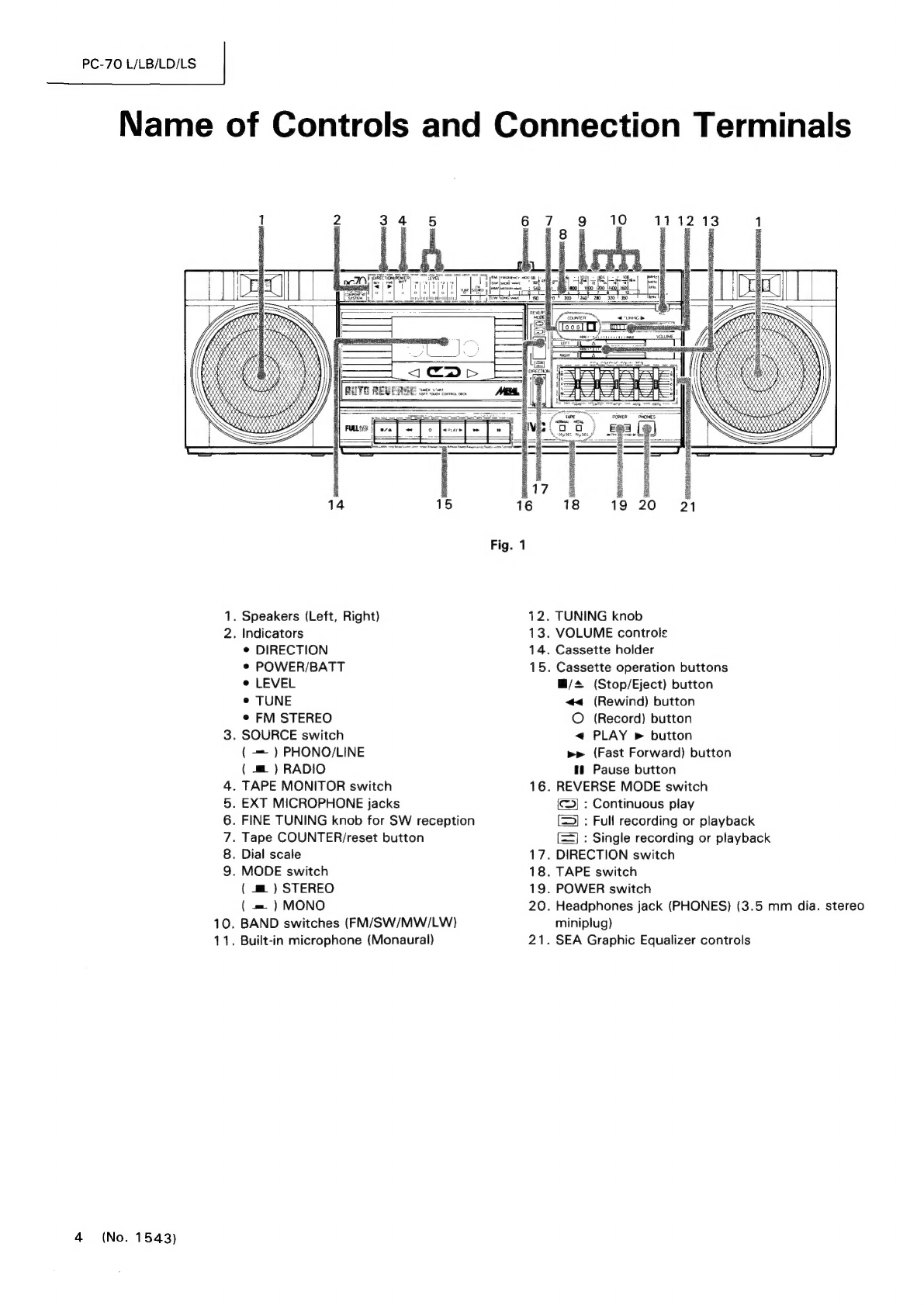
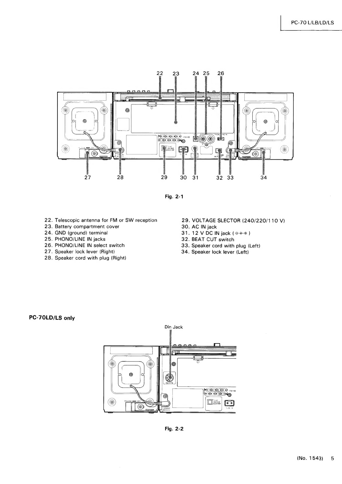
Name
of
Controls
and
Connection
Terminals
......
ite
dvedy
4
SEA
P.C.
Board
Parts
List
.......00...0c.ccccacsecseeceeueeeees
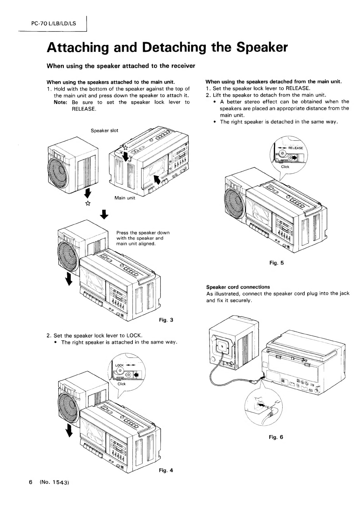
Attaching
and
Detaching
the
Speaker
...................0000
6
Tuner
P.C.
Board
Parts
.............ccccecccusescussceeueseeeenses
Location
of
Main
Parts
...
Tuner
P.C.
Board
Parts
List
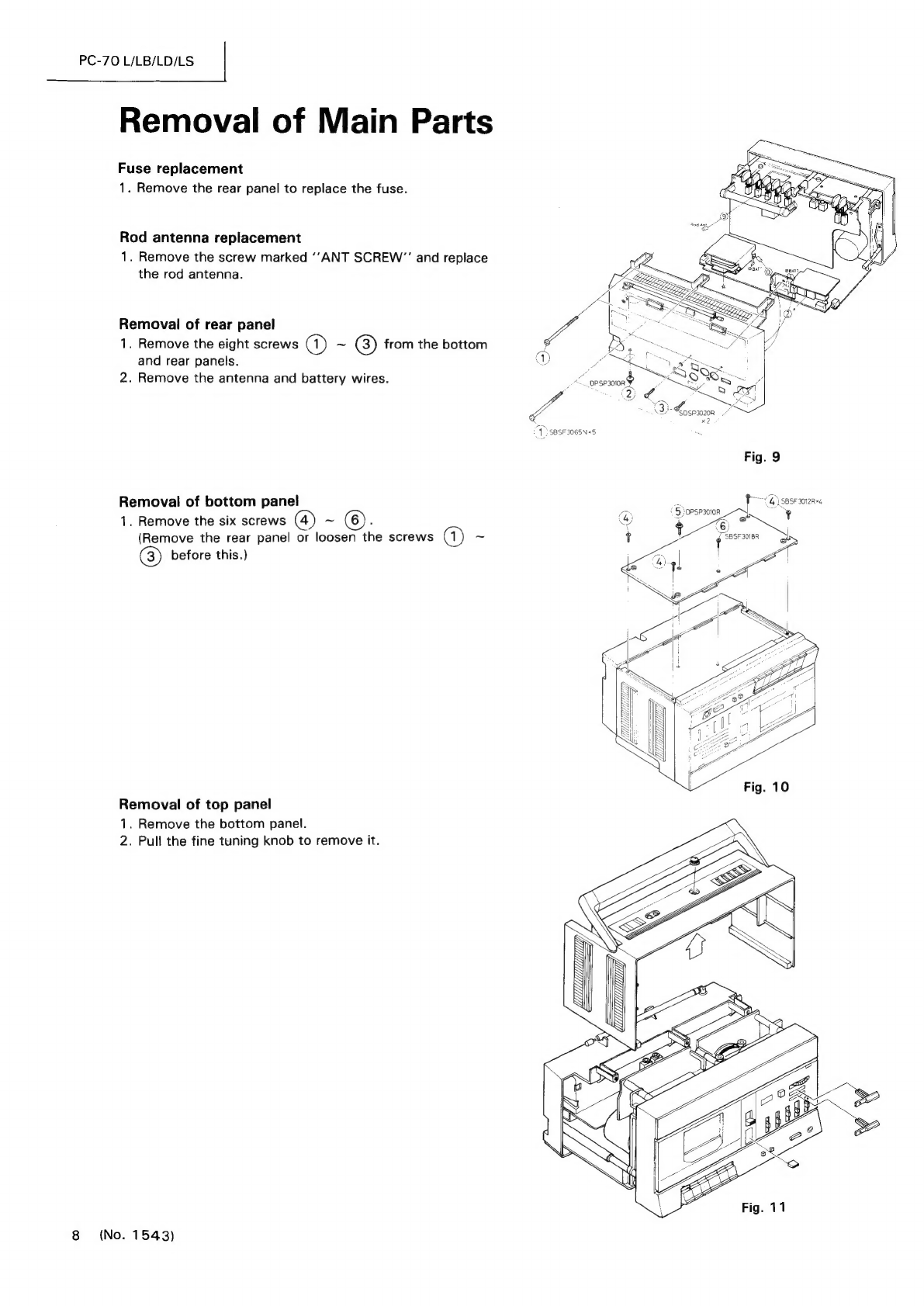
Removal
of
Main
Parts
................0.ccccccecceeceeeseuseaeenes
Phono
P.C.
Board
Parts
....
Mechanism
Parts
............0ccccccsececcecenccecsueccaeeeneeeeees
Phono
P.C.
Board
Parts
List
How
to
Engage
Dial
Cord
...........0.0.ccccececcceeeeeeeeeeesees
Power/LED
P.C.
Board
Parts
...0........c0cccccccececeseeerneees
Main
Adjustment
.....................005
Power/LED
P.C.
Board
Parts
List
Mechanical
Adjustment
Power
Amp
P.C.
Board
Parts
List
.........
Cassette
Amplifier
Adjustment
............00..00cccce
evens
13
Enclosure
Assembly
and
Electrical
Parts
Tuner
Alignment
.........0.06...ccecceeneeceseneeereneneeeeeeeees
Enclosure
Assembly
and
Electrical
Parts
List
............
29
Wiring
Connections
.
Mechanical
Component
Parts
List
..........0...c..c0ceeeeee
Block
Diagram
Mechanical
Component
Parts
Integrated
Circuit
.........0....ccccecesccccaveeeeteeaeeeenes
sage
Exploded
View
and
Parts
List
for
Speaker
Standard
Schematic
Diagram
of
PC-7OL/LB
Speaker
System
Assembly
Parts
List
......0.....0....0605-
(Tuner
Circuit)
......cccccccceeccesceevecesecedsccaeeesecesieeeees
20
Packing
oi
icss.esccsccsbcssscusvsuene
Jin
tievactasSeectraulamiecrestess
se
37
Standard
Schematic
Diagram
of
PC-70LD
Packing
and
Packing
Parts
List
(Tuner
Circuit)
........00cc.ccccccccsecesecsccuuesseueusnes
insertion
ACCOSSOTIES
20.0...
c
cc
cecececceccueucecocuseeecsecaraeuens
Standard
Schematic
Diagram
of
PC-7OL/LB
(Amplifier
Circuit)
......0...0..00..cccccccuceecccneeusecusenesens
21
No.
1543
January
1984