ARMTEL DCN-16U User manual
DCN-16U Exchange
(basic version, version with
pre-installed switching
module DCN-Q4E)
ARMT.665200.001UM
User Manual
Document version 17-11 26.30.11.190
2020

armtel.com
© Armtel info@armtel.com

DCN-16U EXCHANGE
(BASIC VERSION, VERSION WITH PRE-INSTALLED SWITCHING MODULE DCN-Q4E)
User Manual
armtel.com page 1/44
info@armtel.com © Armtel
INTRODUCTION
This User Manual is intended for introducing DCN-16U Exchange of ARMT.665200.001
basic version and version ARMT.665200.001-01 with pre-installed switching processor
module DCN-Q4E (4xE1) ARMT.665200.010 to the User.
DCN-16U exchange is a compact connection unit for subscriber equipment within the
DCN distributed of Public Address and General Alarm system.
Short product name – DCN-16U.
Maintenance personnel for the DCN-16U shall be appointed by the management at
the installation site.
The maintenance personnel shall be required to know the operating procedure of the
DCN-16U to the extent provided for by the user manual.
Duties of the maintenance personnel shall include maintenance of the DCN-16U in
accordance with this user manual.
ATTENTION! In connection with systematic work to improve the design and
manufacturing technology, it is possible some discrepancy between the description and the
supplied product, which does not affect its operation or maintenance.

DCN-16U EXCHANGE
(BASIC VERSION, VERSION WITH PRE-INSTALLED SWITCHING MODULE DCN-Q4E)
User Manual
page 2/44 armtel.com
SAFETY PROVISIONS
During installation and operation of DCN-16U, observe safety precautions laid out in
local regulations on electrical safety.
To avoid electric shock, do not:
−operate the product if its case is not connected to the ground rod;
−operate the product with a damaged power or communication cable;
−the interface cable can be connected and disconnected if the power cable is
disconnected.
ATTENTION! NEVER DISMANTLE THE PRODUCT CONNECTED TO MAINS.
Do not use the product in rooms with high humidity of more than 80% or conductive
dust.
In order to ensure fire safety, follow the following rules:
−before connecting the product to the power supply, make sure the power and
communication cables are properly insulated;
−protect power and communication cables from damage.
The safety provisions for specific operations described in this manual are marked with:

DCN-16U EXCHANGE
(BASIC VERSION, VERSION WITH PRE-INSTALLED SWITCHING MODULE DCN-Q4E)
User Manual
armtel.com page 3/44
info@armtel.com © Armtel
CONTENTS
INTRODUCTION.................................................................................................................................................................... 1
SAFETY PROVISIONS........................................................................................................................................................... 2
CONTENTS .............................................................................................................................................................................. 3
1 DESCRIPTION AND OPERATION................................................................................................................................. 5
1.1 Product description and operation .................................................................................................................. 5
1.1.1 Functions........................................................................................................................................................... 5
1.1.2 Main specifications........................................................................................................................................ 7
1.1.3 Scope of supply ............................................................................................................................................10
1.1.4 Design...............................................................................................................................................................11
1.2 Product components description and operation......................................................................................14
1.2.1 General.............................................................................................................................................................14
1.2.2 DCN-Q4E (4xE1) switching processor module..................................................................................14
1.2.3 DCN-Q4E E1 connection cable ...............................................................................................................16
1.2.4 DCN-16U subscribers connection cable..............................................................................................17
1.3 Subscriber units connected to DCN-16U (with DCN-Q4E)....................................................................18
1.3.1 General information....................................................................................................................................18
1.3.2 DCN-2 Exchange / DCN-Q4E switching processor module (to DCN-16U with
DCN-Q4E) ..................................................................................................................................................................18
1.3.2 Digital ATX (to DCN-16U with DCN-Q4E) ..........................................................................................18
1.3.3 Subscriber units ............................................................................................................................................18
2 INTENDED USE ................................................................................................................................................................21
2.1 Operating limits .....................................................................................................................................................21
2.2 Preparation for use ...............................................................................................................................................21
2.3 Safety precautions.................................................................................................................................................22
2.4 Installation, connection and dismantling .....................................................................................................23
2.5 Operation .................................................................................................................................................................24
2.5.1 Product On/Off .............................................................................................................................................24
2.5.2 Product general performance monitoring routine..........................................................................25
2.5.3 Troubleshooting...........................................................................................................................................28
3 MAINTENANCE................................................................................................................................................................30
4 REPAIR ..............................................................................................................................................................................31
5 STORAGE............................................................................................................................................................................32
6 TRANSPORTATION.........................................................................................................................................................33

DCN-16U EXCHANGE
(BASIC VERSION, VERSION WITH PRE-INSTALLED SWITCHING MODULE DCN-Q4E)
User Manual
page 4/44 armtel.com
7 DISPOSAL...........................................................................................................................................................................34
ANNEX А(reference) Сonnecting optional equipment and power supply.................................................35
А.1 DCN-Q4E E1 connection cable ........................................................................................................................35
А.2 DCN-16U digital subscribers connection cable.........................................................................................38
А.3 Connection to power supply ............................................................................................................................41
А.4 Phantom power supply.......................................................................................................................................42

DCN-16U EXCHANGE
(BASIC VERSION, VERSION WITH PRE-INSTALLED SWITCHING MODULE DCN-Q4E)
User Manual
armtel.com page 5/44
info@armtel.com © Armtel
1 DESCRIPTION AND OPERATION
1.1 Product description and operation
1.1.1 Functions
DCN-16U is designed to operate as a part of DCN-2 or DCN-Q4E-based DCN
communication system as a module of digital subscriber sets to connect the subscriber
devices via Uk0-interface. DCN-16U transmits voice traffic channels and signaling among 15
subscriber Uk0-interfaces and E1 line to a central exchange unit, and it doesn’t function as
an exchange for connections between subscribers. Armtel DCN communication systems
built-up using these products provides for voice communication between loud-speaking
subscriber units made by Armtel LLC, VoIP subscribers, public address and general alarm.
Base version of DCN-16U has advanced features in version with preinstalled DCN-Q4E
switching processor module.
DCN-16U Exchange of ARMT.665200.001-01 version has pre-installed switching
processor module DCN-Q4E (4хЕ1) ARMT.665200.010, which is a small central exchange unit
of DCN system and provides for switching voice channels up to four E1 lines enabling to
connect a subscriber switching unit for 15 digital or analogue interfaces to each of them.
Therefore, maximum capacity of DCN-Q4E-based system can be up to 60 subscribers.
The switching processor module DCN-Q4E intended for use as central exchange unit
of DCN system, at the enterprise of industry and transport. DCN system (Armtel LLC) built
with product provide simplex communication between loud-speaking subscriber devices
manufactured by Armtel LLC, duplex communication with telephony subscribers, paging,
and emergency loud warning.
DCN-16U is installed in control or office rooms.
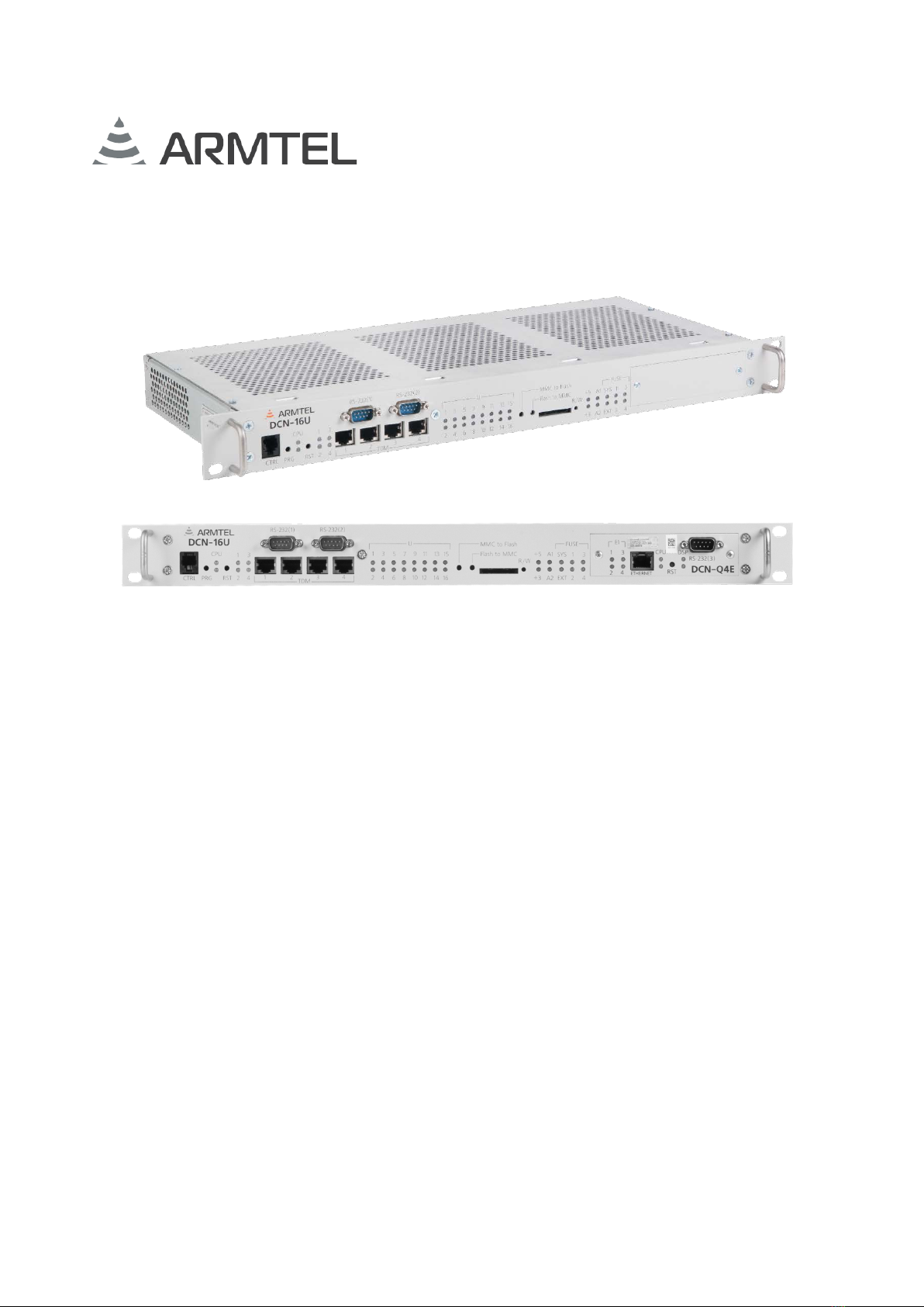
DCN-16U Exchange both versions are shown in Figure 1.
DCN-16U EXCHANGE
(BASIC VERSION, VERSION WITH PRE-INSTALLED SWITCHING MODULE DCN-Q4E)
User Manual
page 6/44 armtel.com
a) version ARMT.665200.001 (base version)
b) version ARMT.665200.001-01 (with pre-installed switching processor module DCN-Q4E)
Figure 1 – DCN-16U Exchange
In DCN-16U Exchange with DCN-Q4E switching processor module DCN-16U Exchange
can be directly connected to a built-in processor module DCN-Q4E. This version of the
product may function as central exchange of DCN system, enabling connection up to 15
digital subscriber units and three E1 lines to it to communicate with DCN system exchange
units or other equipment.
Digital communication system DCN has flexible distributed structure, where single
stations are linked into a single network by E1 digital lines. DCN communication system
station (or central exchange) consists of DCN-2 or DCN-Q4E central exchange with
DCN-16U and DCN-15A exchange equipped with digital and analogue subscriber interfaces
connected to it by E1 lines. E1 lines can also be used as ISDN PRI lines to communicate with
external telecommunication systems or to connect multichannel communication recorders.
DCN IP-gateway providing communication with different IP-devices can also be used as DCN
system station.
Each DCN-16U exchange is a subscriber lines equipment module with 16 Uk0-interfaces
for connecting digital subscriber devices, and an E1 interface for connecting to a DCN central
exchange (16th interface is not used). Digital subscriber interfaces enable to connect both
Armtel equipment (DIS, DW, А8, DWEx, DTS5, Analogue subsystem module), and third-party
equipment with Uk0-interface (ISDN telephones, ISDN adapters for analogue telephone
connection, DECT stations with ISDN interfaces etc.). In order to improve intercom system
quality when operating Armtel subscriber units, an expanded sound transmit frequency band
of 6.8 kHz is used. DCN-16U is connected to a central exchange of DCN system by E1 line,
which is used for transmitting voice traffic channels and signaling between the central
exchange and subscriber units. Therefore, all functions of communication and control of
subscriber units are implemented in the central exchange of DCN system and DCN-16U
subscriber exchange performs no functions if not connected there to.

DCN-16U EXCHANGE
(BASIC VERSION, VERSION WITH PRE-INSTALLED SWITCHING MODULE DCN-Q4E)
User Manual
armtel.com page 7/44
info@armtel.com © Armtel
Being a part of DCN digital intercom system DCN-16U exchange functions as follows:
−Connection of up to 15 devices by the lines of digital double-wire subscriber
interfaces Uk0at a distance of max. 6 km.
−Transmission of voice communication channels and signaling between E1 line
used for connection to DCN system central exchange and 15 digital subscriber
interfaces Uk0.
−Control and indication on the front panel of subscriber interface and E1 line
status.
−Phantom power supply of end units by Uk0subscriber interface line.
Being a part of DCN digital intercom system DCN-16U Exchange provides for
connection with the following devices:
−DIS and DIS-TOP digital desktop call stations.
−DW/DWEx explosion and weather proof digital loud-speaking call stations.
−DTS5 and DTS-TOP multifunction desktop digital phones.
−Analogue subsystem modules for communication with analogue equipment
(one LF-interface line) and иswitching control circuits (eight discrete
input/output lines).
−А8/A8Ex explosion and weather proof digital duplex call stations (currently out
of production).
−ISDN-telephones and other third-party devices with Uk0-interface.
DCN-16U Exchange is ready for operation as supplied and no programming is required
during operation except for assignment of subscriber unit connection ports. Operation of
DCN-16U Exchange and subscriber units connected to it is managed by a central exchange
of DCN system connected to DCN-16U via E1 line.
Detailed description of functions and programming methods of DCN system exchange
units are given in RMLT.465275.002 “DCN Communication System. User Manual. Part 1. User
Manual” and “DCN Communication System. User Manual. Part 2. Administrator Manual”.
1.1.2 Main specifications
DCN-16U exchange has the following interfaces:
−16 double-wire subscriber interfaces Uk0– for basic access to end equipment.
16th interface is not used.
−Two serial interfaces RS-232 (V.24) – for PC connection at bit rate up to 115 kB/s,
used for diagnostics and programming of the exchange at the manufacturer.

DCN-16U EXCHANGE
(BASIC VERSION, VERSION WITH PRE-INSTALLED SWITCHING MODULE DCN-Q4E)
User Manual
page 8/44 armtel.com
−E1 (G.703/G.704) – for connection to DCN system central exchange via E1 line.
Uk0 interface provides for:
−Distance from the exchange to a subscriber is up to 6 km when using non-
symmetrical cable.
−Bandwidth for voice transmission – 6.8 kHz (when using two B-channels).
−Phantom power supply to subscriber units using PoU (Power-over-U) function
at load current up to 250 mA.
−ANSI T1.602 – interface of base channel, it is a procedure of accessing to a
primary channel, D-channel (LAP-D), communication protocol is BRI.
−Coding the signal in the line – as per 2B1Q pattern according to ITU-T
recommendation.
The product supports standard communications protocols as follows:
−Q.931 – for procedure of establishing network-level communication of OSI
model (third-level specification for D-channel), provides for managing calls and
a set of options, circuit switched call routing of service subscriber;
−I.452 (Q.932) – general procedures for ISDN options managing;
−Q.921 (LAP-D) – to determine frame structure and frame field content at channel
level of OSI model (D-channel), User-Network interfaces is ISDN – specification
of communication data level;
−I.430 of recommendations of ITU-T (ISDN standard) – for organizing data
transmission at physical level of OSI model and basic access;
−I.431 of recommendations of ITU-T (ISDN standard) – for organizing data
transmission at physical level of OSI model and main access;
−ANSI T1.604 – minimum set of services of ISDN BRI;
−I.432 of recommendations of ITU-T (ISDN standard) – User-network interface B-
ISDN – physical level specification;
−DSS1 – subscriber signaling protocol.
Main specifications and performance characteristics of DCN-16U Exchange are given
in the Table 1.

DCN-16U EXCHANGE
(BASIC VERSION, VERSION WITH PRE-INSTALLED SWITCHING MODULE DCN-Q4E)
User Manual
armtel.com page 9/44
info@armtel.com © Armtel
Table 1 – Main specifications
Parameter Value
Rated voltage, V
-48
Supply voltage range, V
from -36 to -60
Consumption power, at most, (excluding phantom supply), W
20
Maximum number of switched subscriber devices, pcs.
15
Electrical protection class (under GOST IEC 61140-2012)
III
Climatic category (under GOST 15150-69)
NF4.11)
Protection degree provided by shells (under GOST 14254-2015) (IP-code)
IP40
Seismic resistance category (under NP-031-01)
I
Safety Class (under NP-001-15*)
3Н (Normal)
Operating temperature range, ºC
from - 5 to + 55
Atmospheric pressure, kPa
from 84 to106,7
Relative air humidity at 25 °С, %
up to 80
Dimensions, maximum, mm
483×227×44
Weight, max, kg (excluding weight of DCN-16U subscribers connection
cables and DCN-Q4ЕE1 connection cable)
2,5
* The product conformity with Safety Class 4Нunder NP-001-15.
1)
Conditioned locations or partially conditioned air.
The product enables/disables the configured subscriber units without power shutdown
and reboot. DCN-16U has protection against incorrect polarity of power supply connection.
ATTENTION: WHEN CONNECTING PHANTOM POWER ADHERENCE TO
INSTRUCTIONS OF MANUALS FOR CONNECTED SUBSCRIBER UNITS IS SCTRICTLY
REQUIRED! FAILURE TO FOLLOW THE REQUIREMENTS MAY CAUSE DAMAGE TO
THE EXCHANGE AND/OR SUBSCRIBER UNIT!
DCN-16U EXCHANGE
(BASIC VERSION, VERSION WITH PRE-INSTALLED SWITCHING MODULE DCN-Q4E)
User Manual
page 10/44 armtel.com
1.1.3 Scope of supply
Scope of supply for DCN-16U is given in the Table 2.
Table 2 – Scope of supply
Identification Name
Quantity,
pcs.
Note
ARMT.665200.001*
DCN-16U Exchange
1
Additional information on scope of supply
ARMT.665200.102
DCN-16U Subscribers connection cable
1
ARMT.665200.103
ISDN PRI (E1) module
1
ARMT.665200.010**
Switching processor module DCN-Q4E
(4хE1)
1
ARMT.665200.139**
DCN-Q4ЕConnection cable via Е1
1
PC 4/3-STF-7,62 socket
1
MJ-C-6,47 jumper
32
Operational documentation
ARMT.665200.001PP
Product Passport
1
ARMT.665200.001UM
User Manual
1
* Version according to the contract for the supply
** For version ARMT.665200.001-01

DCN-16U EXCHANGE
(BASIC VERSION, VERSION WITH PRE-INSTALLED SWITCHING MODULE DCN-Q4E)
User Manual
armtel.com page 11/44
info@armtel.com © Armtel
1.1.4 Design
DCN-16U Exchange mounted into a 19-inch rack (cabinet). DCN-16U external and
overall dimensions are shown in the Figure 2.
Figure 2 - DCN-16U external and overall dimensions
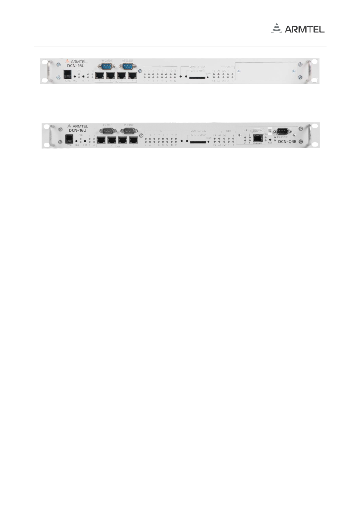
Front panel of DCN-16U with pre-installed DCN-Q4E module and connector and LED
indicators is shown in the Figure 3.
Figure 3 – DCN-16U Front panel
Note – All LEDs used in Front panel are two-color.
DCN-16U Front panel contains:
−CTRL – RJ-12 process connector (not used);
−PRG – hidden button for enabling software loading mode (used in initial loading
of software at manufacturer);
−CPU – CPU1 (top) status indicator CPU, CPU2 is not used;
−RST – reset button;

DCN-16U EXCHANGE
(BASIC VERSION, VERSION WITH PRE-INSTALLED SWITCHING MODULE DCN-Q4E)
User Manual
page 12/44 armtel.com
−1…4 – indicators of 1…4 E1 line connection status. During operation indicator of
E1 line used for connection to DCN central exchange is only active (E1 line 4
used by default);
−RS-232 (1 and 2) – RS-232 interface sockets for PC connection at product
diagnostics and configuration at manufacturer;
−TDM – 1…4 (RJ-45 type) sockets for PCM cable connections (not used);
−
1…16 U – indicators of subscriber unit connection port status. Port 16 is not used;
−+5, +3 – indicators of + 3.3 V, + 5 V voltages of secondary power supply;
−А1, А2 – Failure 1, Failure 2. In case of failure signals states of A1, A2 indicators
are equal to the states of К1, К2 error relays;
−FUSЕ– group of indicators of fuse state:
−SYS – status indicator of DCN-16U Main system fuse, installed in main supply
voltage circuit 48 V;
−EXT – external failure source status indicator;
−1…4 – status indicators of subscriber phantom power fuses.
Front panel of DCN-Q4E (only in version with DCN-Q4E module). is shown in the
Figure 4.
Figure 4 – DCN-Q4E Front panel
DCN-Q4E Front panel contains:
−«1…4» Е1 – Е1 port status indicators (connected devices);
−ETHERNET – RJ-45 interface socket for remote access to DCN-Q4E from PC;
−CPU – CPU1 (top) is CPU status indicator, CPU2 (bottom) reserved;
−RST – CPU reset button;
−DSP – DSP1 (top) is DSP status indicator, DSP2 (bottom) – DSP with CPU link
status;
−RS-232(3) – serial interface socket for diagnostic computer connection.

DCN-16U EXCHANGE
(BASIC VERSION, VERSION WITH PRE-INSTALLED SWITCHING MODULE DCN-Q4E)
User Manual
armtel.com page 13/44
info@armtel.com © Armtel
Back panel of DCN-16U with connectors and fuses is shown in the Figure 5.
Figure 5 – DCN-16U Back panel
DCN-16U Back panel contains:
−terminals for DCN-16U case grounding;
−DCN-Q4U Lines blank cover;
−Fuses – group of power supply fuses 5×20 2 А250 V:
−PoU 1…16 – subscriber phantom power fuses, groups by 4 Uk0 ports;
−Main – DCN-16U system fuse installed in 48V supply voltage circuit of the
main board.
−-48 0V GND – three-pin plug of DCN-16U power cable connection;
−Fantom Power – jumper strip for phantom power supply to subscriber units;
−Subscriber Lines Uk0– 64-pin plug of DIN41612С-64М, to which DCN-16U
subscribers connection cable socket is connected.
−DCN-Q4U Lines – 25-pin socket DRB-25FA of DCN-Q4ЕE1 connection cable
(only in version with DCN-Q4E module).

DCN-16U EXCHANGE
(BASIC VERSION, VERSION WITH PRE-INSTALLED SWITCHING MODULE DCN-Q4E)
User Manual
page 14/44 armtel.com
1.2 Product components description and operation
1.2.1 General
DCN-16U components are as follows:
−DCN-Q4E switching processor module (only in DCN-16U with DCN-Q4E module);
−DCN-Q4ЕE1 connection cable (only in DCN-16U with DCN-Q4E module);
−DCN-16U subscribers connection cable.
1.2.2 DCN-Q4E (4xE1) switching processor module
DCN-Q4E switching module is designed for creating small DCN system. It is an
exchange unit with four E1-interfaces. DCN-Q4E functions are similar to those of DCN-2.
DCN-Q4E switching module enables to build up industrial communication system suitable
for up to 60 digital and analogue subscribers connection with DCN-2 functionality being
available to them.
As a part of digital intercom DCN system DCN-Q4E switching processor unit provides
for the functions as follows:
−switching digital communication channels between E1 line used for access to
subscriber and other exchange units of ISDN network;
−two-way voice communication between subscriber units;
−individual call of any subscriber
−call group of subscribers;
−single PA/GA of subscribers by intercom;
−zonal (group) PA/GA of subscribers by intercom;
−free subscriber numbering;
−order of subscriber call preference with possibility of arbitrary assignment of
connection priorities;
−playback of pre-recorded audio fragments;
−manual or automatic playback of recorded alarm signals, announcements and
messages;
−unification of two or more central DCN exchanges to integrated communication
system;

DCN-16U EXCHANGE
(BASIC VERSION, VERSION WITH PRE-INSTALLED SWITCHING MODULE DCN-Q4E)
User Manual
armtel.com page 15/44
info@armtel.com © Armtel
−connection of external Exchanges to DCN communication system by ISDN PRI
lines;
−local and remote (via IP-network) monitoring, diagnostics and configuring of
the central ex-change and subscriber units connected to it.
ВDCN-Q4E has the following interfaces:
−4 E1 (G.703/G.704) lines – for connection of subscriber exchanges DCN-16U,
DCN-15A, DCN modules IP-gateway, multichannel digital communications
recorders, other stations of DCN system and digital ATX;
−Ethernet (RJ-45 socket) – for remote access to DCN-2 Exchange central
processor from system administrator’s PC via IP-network;
−RS-232 (V.24) – serial interface, process connector for service purposes.
The product supports standard communications protocols as follows:
−Q.931 – for procedure of establishing network-level communication of OSI
model (third-level specification for D-channel), provides for managing calls and
a set of options, circuit switched call routing of service subscriber;
−I.452 (Q.932) – general procedures for ISDN options managing;
−Q.921 (LAP-D) – to determine frame structure and frame field content at channel
level of OSI model (D-channel), User-Network interfaces is ISDN;
−I.430 of recommendation of CCITT (ISDN standard) – for organizing data
transmission at physical level of OSI model and basic access;
−I.431 of recommendations of CCITT (ISDN standard) – for organizing data
transmission at physical level of OSI model and main access;
−ANSI T1.604 – minimum set of services of ISDN BRI;
−I.432 of recommendations of CCITT (ISDN standard) – User-network interface B-
ISDN – physical level specification;
−DSS1 – subscriber signaling protocol.
In terms of design DCN-Q4E module being a part of DCN-16U Exchange is a printed
circuit board to be enclosed into DCN-16U exchange, and powered from its main board. E1
line is connected through DRB-25FA socket on the back panel of the module by means of
special cable. The product enables/disables devices by E1 lines without power shutdown and
reboot.
DCN-16U EXCHANGE
(BASIC VERSION, VERSION WITH PRE-INSTALLED SWITCHING MODULE DCN-Q4E)
User Manual
page 16/44 armtel.com
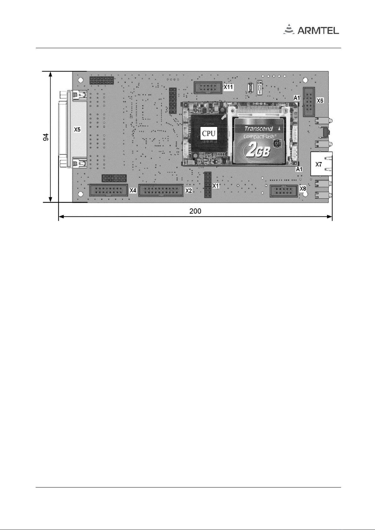
The Figure 6 shows DCN-Q4E module board with overall dimensions.
Figure 6 – DCN-Q4E board with overall dimensions
Maximum height of the parts on the board doesn’t exceed 30 mm.
There are electronic parts on DCN-Q4E module for its connection and functioning,
including:
−А1 – connector for VDX-6300-based (ICOP) CPU module;
−Х1 – debugging connector for communication with DSP signal processor unit;
−Х5 – 25-pin socket DRB-25FA for E1 cable connection;
−Х6 – socket for connection of RS-232(3) serial interface cable on front panel;
−Х7 –
RJ-45 socket of Ethernet interface for connection of module administrating PC;
−Х8 – socket for supply of power voltage from DCN-16U main board.
Other sockets/connectors on the module board are reserved for service purposes.
1.2.3 DCN-Q4E E1 connection cable
DCN-Q4ЕE1 connection cable is intended for connection to DCN-Q4E switching
processor module being a part of DCN-16U exchange, up to four DCN-type exchange units.
In addition, it enables to connect digital Exchanges (or other products) by digital E1 lines,
but the number of DCN exchanges connected decreases to the number of such products. Е1
cable is a passive adapter. Е1 cable is connected to DCN-Q4E switching processor module
by means of D-SUB-25Аtype socket from one end, and form another end its printed circuit

DCN-16U EXCHANGE
(BASIC VERSION, VERSION WITH PRE-INSTALLED SWITCHING MODULE DCN-Q4E)
User Manual
armtel.com page 17/44
info@armtel.com © Armtel
board with 35/7.5 DIN-rail mountable guides is installed into 19 inch rack. Cable view with
overall dimensions is given in the Annex A.
1.2.4 DCN-16U subscribers connection cable
DCN-16U subscribers connection cable is intended for connecting sixteen U-interface
lines, four E1 lines, external error message signal and generating А1, А2 failure signals. The
cable is connected to DCN-16U Exchange Back panel through C type DIN41612 socket from
one end and from another end it is mounted into 19-inch rack (cabinet) by means of printed
circuit board with guides for clamping on DIN-rail 35/7.5.
DCN-16U cable is a passive adapter enabling to switch connection cables of subscriber
units to DCN-16U Exchange DIN41612С-64Мplug with high density of contact
configuration.
DCN-16U subscribers connection cable with specifications and overall dimensions is
shown in Annex A.

DCN-16U EXCHANGE
(BASIC VERSION, VERSION WITH PRE-INSTALLED SWITCHING MODULE DCN-Q4E)
User Manual
page 18/44 armtel.com
1.3 Subscriber units connected to DCN-16U (with DCN-Q4E)
1.3.1 General information
Loud-speaking intercoms are designed as the subscriber equipment for use in digital
intercom and public address/general alarm communication systems. It is powered from
centralized power supply with DC voltage of 48 V or by phantom power.
Interface of subscriber unit connection is Uk0. When transmitting audio data both
B-channels are engaged enabling to broaden audio transit bandwidth among loud-speakers
up to 6.8 kHz.
A subscriber unit generally has a built-in speaker and microphone, digital port and a
set of programmable buttons / keys. Programmable button / key functions are assigned
during system programming.
Loud-speaking call stations can be desktop and wall-mounted. It is equipped with LF
circuit of two-way PA/GA, a set of buttons/keys with indication, may have auxiliary amplifier
and control relay. These are loud-speaking intercoms manufactured by Armtel Company
such as DW, DWEx, DIS and DIS-TOP call stations.
1.3.2 DCN-2 Exchange / DCN-Q4E switching processor module (to DCN-16U with
DCN-Q4E)
The DCN System can include several central exchange interconnected by E1 lines with
the extended Armtel DSS protocol. The Armtel DSS protocol provides full-featured
integration of exchanges into communication system. As the central exchange of
the DCN system can be used DCN-2 Exchange and DCN-Q4E switching processor module.
Ones have unified software but different capacities and design.
1.3.2 Digital Exchange (to DCN-16U with DCN-Q4E)
External digital Exchange or other device supporting EDSS1 protocol and E1 interface
(G.703/G.704). In this case, the number of DCN-16U is reduced by the number of busy
interfaces.
1.3.3 Subscriber units
DIS and DIS-TOP digital desktop call station
DIS and DIS-TOP digital desktop call station have from eight to 32 programmable keys
with illumination (DIS) and 42 keys (DIS-TOP). DIS-TOP call station is additionally equipped
with 4.3 inch visual TFT-display with LED illumination. Call stations are connected to Uk0
interface using RJ-45 socket. Up to four DIS expansion units with eight to 48 programmable
keys can be connected to one DIS, DIS-TOP may have up to ЕС-ТОР expansion units with 42
keys connected.
Table of contents
Other ARMTEL Switch manuals


