ARMTEL DCN-2 Central Exchange User manual
DCN-2 Central Exchange
ARMT.665200.003UM
User Manual
Document version 13 26.30.11.110
2021
ENG

armtel.com
© Armtel info@armtel.com

ENG
INTRODUCTION
This User Manual is intended for introducing «DCN-2 Central Exchange»
ARMT.665200.003 manufactured by Armtel LLC, Russia and it is intended to familiarize the
user with the switch device and the procedure for its operation at the installation site.
The DCN-2 Central Exchange is a compact switching node of the digital system of
operational and technological communication and loud notification DCN.
Short name of the product –DCN-2.
Maintenance personnel for DCN-2 shall be appointed by the management at the
installation site. The maintenance personnel shall be required to know the operating
procedure of DCN-2 to the extent provided for by the User Manual.
Duties of the maintenance personnel shall include maintenance of DCN-2 by this User
Manual.

ENG
SAFETY PROVISIONS
When using DCN-2 for its intended purpose, it is necessary to comply with the
requirements of safety measures defined by the "Rules on Labor Protection during Operation
of Electrical Installations" when working with electrical receivers with a voltage of up
to 1000 V.
For fire safety reasons, the following rules must be observed:
before connecting, check for damage to the insulation of the loop;
avoid damaging the loop.
To avoid the risk of electric shock, it is forbidden:
to operate the product with a damaged power and communication cable.
It is strictly forbidden to disassemble the product connected to the central.
Do not use the product in rooms with high humidity (above 80%) or the presence of
conductive dust.
The safety provisions relating to the specific operations outlined in this manual are
indicated by the following sign:

ENG
CONTENTS
INTRODUCTION.................................................................................................................................................................... 1
SAFETY PROVISIONS........................................................................................................................................................... 2
CONTENTS .............................................................................................................................................................................. 3
1 DESIGN AND DESCRIPTION ......................................................................................................................................... 5
1.1 Product description and operation .................................................................................................................. 5
1.1.1 Features ............................................................................................................................................................. 5
1.1.2 Specifications................................................................................................................................................... 7
1.1.3 Scope of supply .............................................................................................................................................. 9
1.1.4 Design...............................................................................................................................................................10
1.1.5 Marking............................................................................................................................................................17
1.1.6 Packing.............................................................................................................................................................18
1.2 Description and operation of product components................................................................................19
1.2.1 General information....................................................................................................................................19
1.2.2 DCN-2 connection cable...........................................................................................................................19
1.2.3 4E1 DCN-2 board.........................................................................................................................................19
1.3 Description of devices connected to unit ....................................................................................................20
1.3.1 Redundancy module DCN-2....................................................................................................................20
1.3.2 Monitoring system ......................................................................................................................................20
1.3.3 DCN-2 central exchange or DCN-Q4E switching processor module.......................................20
1.3.4 DCN-16U Exchange unit............................................................................................................................20
1.3.5 DCN-15A analogue interface module..................................................................................................20
1.3.6 Multichannel communications recorder .............................................................................................21
1.3.7 E1/IPN E1/IPN module for DCN IP Gateway......................................................................................21
1.3.8 E1/SIP module for DCN IP Gateway......................................................................................................21
1.3.9 E1/FTP module for DCN IP Gateway.....................................................................................................21
1.3.10 Digital ATS....................................................................................................................................................22
2 INTENDED USE ................................................................................................................................................................23
2.1 Operating limits .....................................................................................................................................................23
2.2 Preparation for use ...............................................................................................................................................23
2.3 Safety measures when using the product for its intended purpose..................................................24
2.4 Installation, connection, and dismantling....................................................................................................24

ENG
2.5 Operation .................................................................................................................................................................26
2.5.1 Procedure of actions of the service personnel when using the product................................26
2.5.2 Configuring product links.........................................................................................................................26
2.5.3 Product switch-on and switch-off..........................................................................................................26
2.5.4 Product functionality control...................................................................................................................27
2.5.5 Troubleshooting...........................................................................................................................................29
3 MAINTENANCE................................................................................................................................................................31
3.1 General guidelines ................................................................................................................................................31
3.2 Safety precautions.................................................................................................................................................31
3.3 Maintenance procedure......................................................................................................................................31
3.4 Checking the functionality of the product...................................................................................................32
4 REPAIR ..............................................................................................................................................................................33
5 STORAGE............................................................................................................................................................................34
6 TRANSPORTATION.........................................................................................................................................................35
7 DISPOSAL...........................................................................................................................................................................36
APPENDIX А (Reference) Product connection.........................................................................................................37
А.1 DCN-2 connection cable....................................................................................................................................37
А.2 Power supply cable ..............................................................................................................................................43

ENG
1 DESIGN AND DESCRIPTION
1.1 Product description and operation
1.1.1 Features
The DCN-2 Central Exchange is intended for use as a central exchange as part of a digital
system of loud-speaking operational and technological communication and loud
notification DCN, at industrial and transport enterprises. DCN communication systems
manufactured by Armtel LLC, built with these products, provide simplex communication
between loudspeaker subscriber devices manufactured by Armtel LLC, duplex
communication with telephony subscribers, search communication, and emergency loud
notification.
DCN-2 can be used in metallurgical, chemical, oil refining, nuclear (including nuclear
power plants), gas, and oil-producing industries and similar to them in terms of application,
as well as in transport.
The DCN-2 Central Exchange is installed in telecommunication cabinets or racks located
in hardware, control rooms, or office premises and operates in the temperature range from
minus 5 °C to plus 55 °C with a relative humidity of up to 80%.
DCN digital communication system has a flexible distributed structure, where individual
stations are connected in the unified network by E1 digital streams. DCN communication
system station (or central station), in its turn, consists of DCN-2 central exchange unit or
DCN-Q4E switching processor module, to which DCN-16U and DCN-15A subscriber
exchanges equipped with digital or analogue subscriber interfaces are connected through
E1 stream. Such architecture enables to create large, territorially distributed communication
systems with minimum costs for central equipment and cable infrastructure.
DCN-2 is a compact central exchange of the DCN system. DCN-2 central exchange is
built by a modular approach and can be equipped with one to four boards of 4Е1 DCN-2
modules. Each 4Е1 DCN-2 module provides generating four E1 streams, each of which can
be connected to a DCN-16U or DCN-15A module with 15 digital or analog interfaces,
respectively. Thus, the maximum capacity of DCN-2 central exchange is defined by the
number of installed modules 4E1 and can comprise up to 240 subscribers.
To expand the subscriber capacity and communication with other systems, it is possible
to connect to DCN-2 other DCN-2 central exchanges and/or DCN-Q4E. In this case, inter-
switch protocol Armtel DSS is used, providing fully functional communication between these
exchange units. E1 streams can be also used as ISDN PRI lines for communication with
external telecommunication systems or for the connection of multichannel communications
recorders. The modules of the IP gateway, providing communication with various IP devices
can also serve as the stations of the DCN system. In order to improve PA quality, the

ENG
expanded frequency bandwidth from 0,3 to 7 kHz is used in operation with the subscriber
devices manufactured by Armtel LLC.
DCN-2 provides the following functions incorporated into DCN digital intercom
system:
switching of digital communication channels between E1 streams used for
access to subscriber devices and other exchanges of ISDN network;
establishing two-way voice communication between subscriber devices;
capability of individual call to any subscriber;
capability of subscribers group call;
individual announcements to subscribers by PA;
free numbering of subscribers;
prioritized order of subscribers calling with the possibility of arbitrary
assignment of connection priorities;
playback of pre-recorded sound fragments from speech memory to both a
single subscriber and a group of subscribers;
playback of pre-recorded sound fragments: manual, scheduled, automatic when
the "dry contact" is closed or by MODBUS command;
interaction with the backup module of the DCN-2 Central Exchange to ensure
the automatic connection of the DCN-2 backup central exchange instead of the
faulty one in case of an accident in the DCN-2 Central Exchange;
connection of two or more DCN central exchanges into the unified
communication system;
connection of external ATSs to DCN communication system via ISDN PRI lines;
local and remote monitoring (via IP network), diagnostics, and configuration of
the central exchange unit and subscriber devices connected to it.
A detailed description of DCN-2 functional area and device programming practice are
given in document RMLT.465275.002 «DCN Communication System. User Manual. Part 2.
Administrator Manual».

ENG
1.1.2 Specifications
DCN-2 has the following interfaces:
from 4 to 16 of E1 (G.703/G.704) –for connection DCN-16U, DCN-15A
subscriber exchange units, DCN IP-gateway modules, multichannel digital
communications recorders, other stations (central stations) of DCN system and
digital ATSs;
Ethernet (RJ-45 connector) –for remote access to CPU of DCN-2 Central
Exchange from the system administrator computer via IP-network;
RS-232 (V.24) –serial interface, technology connector for service purposes (not
used).
The product maintains the following standardized communication protocols:
Q.931 –for establishing communications at OSI network layer model (Layer 3
specification for D-channel), provides control of your calls and a set of additional
services, call routing service for users with switched channels;
I.452 (Q.932) –general procedures for controlling ISDN additional services;
ANSI T1.604 –a minimum set of services of basic ISDN channel interface;
Q.921 (LAP-D) –for determining the structure and content of the picture frame
on the field data link layer of OSI model (D channel), a network ISDN user
interface –specification of coherent information level;
I.430 CCITT recommendation (standard ISDN) to arrange the information in the
physical layer of OSI model and basic access;
I.431 CCITT recommendation (standard ISDN) to arrange the information in the
physical layer of OSI model and basic access;
I.432 CCITT recommendation (standard ISDN) - network interface of B-ISDN user
- Physical Layer Specification;
DSS1 –subscriber signaling protocol.

ENG
The main specifications and performance characteristics of DCN-2 are given in Table 1.
Table 1 –The main specifications and performance characteristics
Parameter
Value
Rated voltage, V
-48
Supply voltage range, V
from -36 to -60
Consumption power, maximum, W
20
Electric protection class (under GOST IEC 61140-2012
III
Type of climatic design, type of atmosphere according to GOST 15150-69
NF4.1
The degree of protection provided by the shells according to
GOST 14254-2015
IP20
Category of seismic resistance according to NP-031-01
I
Safety class according to NP-001-015* and NP-033-11
3N
Air temperature range, ºC
from - 5 to + 55
Atmospheric pressure, kPа
from 84 to 106,7
Relative air humidity at 25 °С, %
to 80
Casing dimensions, maximum, mm
482×346×43
(19" 1U)
Weight, maximum, kg (excluding the weight of DCN-2 connection cable)
See Table 3
*Compliance of the product with safety class 4N according to NP-001-15 is allowed
The product provides connection/disconnection of devices via E1 lines without
switching off the DCN-2 power supply and restarting it.
The DCN-2 provides protection against incorrect polarity of the power supply
connection.
To connect 16 devices equipped with the E1 interface to the DCN-2 and issue alarm
signals A1, A2, the DCN-2 connection cable included in the central exchange package is
intended. The appearance of the DCN-2 connection cable is given in Appendix A.

ENG
1.1.3 Scope of supply
The scope of supply of the DCN-2 is given in Table 2.
Table 2 –Scope of supply
Identification
Name
Quanti-
ty, pcs.
Note
ARMT.665200.003*
DCN-2 Central Exchange
1
Socket PC 4/3-STF-7,62
1
Additional information about the completeness
ARMT.665200.124
DCN-2 Connection cable
1
Operational documentation
ARMT.665200.003PP
Product Passport
1
ARMT.665200.003UM
User Manual
1
* Version in accordance with the supply package. Number of 4E1 DCN-2 boards depending
on the version (see Table 3)
ENG
1.1.4 Design
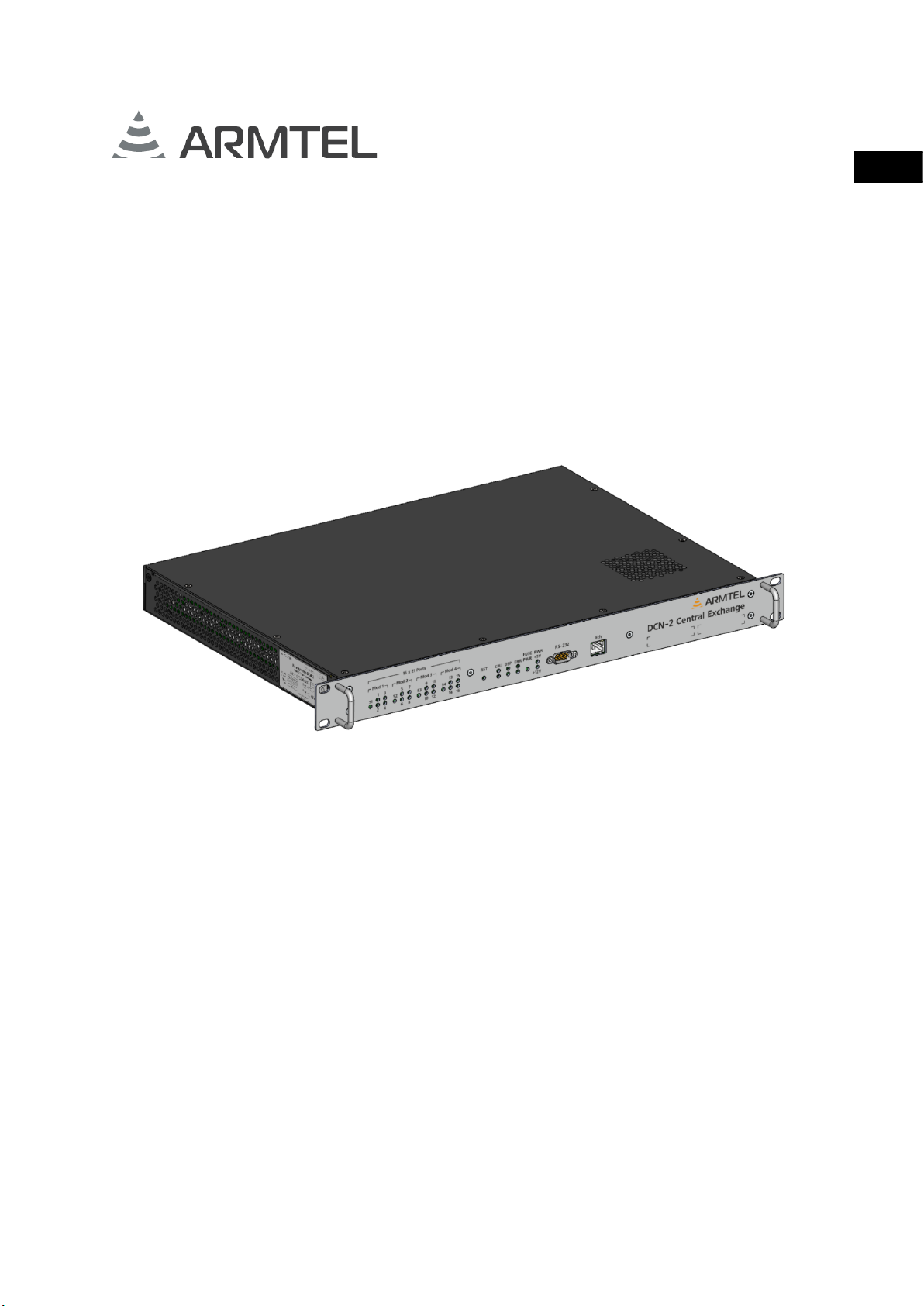
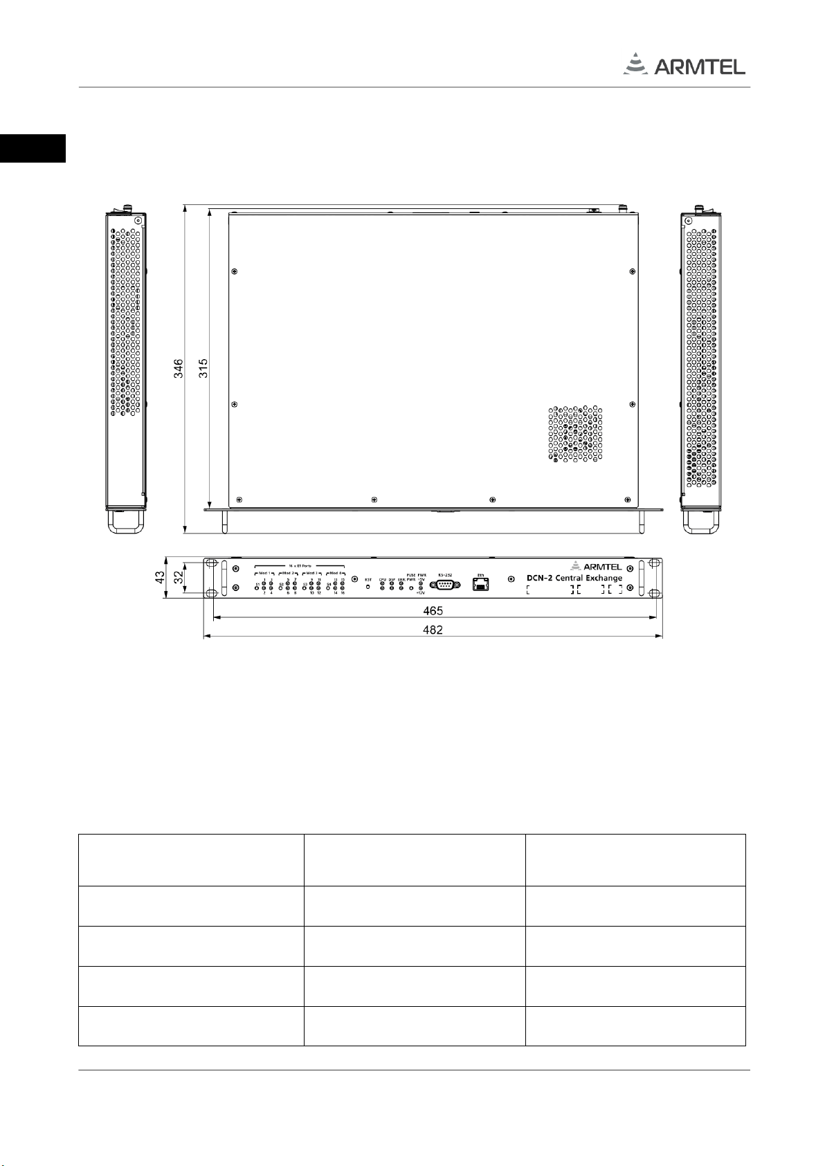
DCN-2 is designed for installation in 19" cabinet (rack). The external appearance and
overall dimensions of DCN-2 are illustrated at Figure 1.
Figure 1 –External appearance and overall dimensions of DCN-2
Note –The manufacturer reserves the right to change the appearance of the product without
affecting the installation dimensions and operation of the product
DCN-2 is manufactured in four versions, depending on the number of installed boards
4E1 DCN-2. The unit hardware versions are shown in Table 3.
Table 3 –Versions of DCN-2
Identification
Number of boards 4E1
Weight, maximum, kg
ARMT.665200.003
1
3,00
ARMT.665200.003-01
2
3,05
ARMT.665200.003-02
3
3,10
ARMT.665200.003-03
4
3,15
ENG
DCN-2 is composed of:
CPU central processor;
DSP switching module;
4E1 stream processing modules.
The central processor controls channel switching in the switching field located on DSP
module. DSP module is also used for storing and replaying the sound messages that are
preloaded to its non-volatile memory.
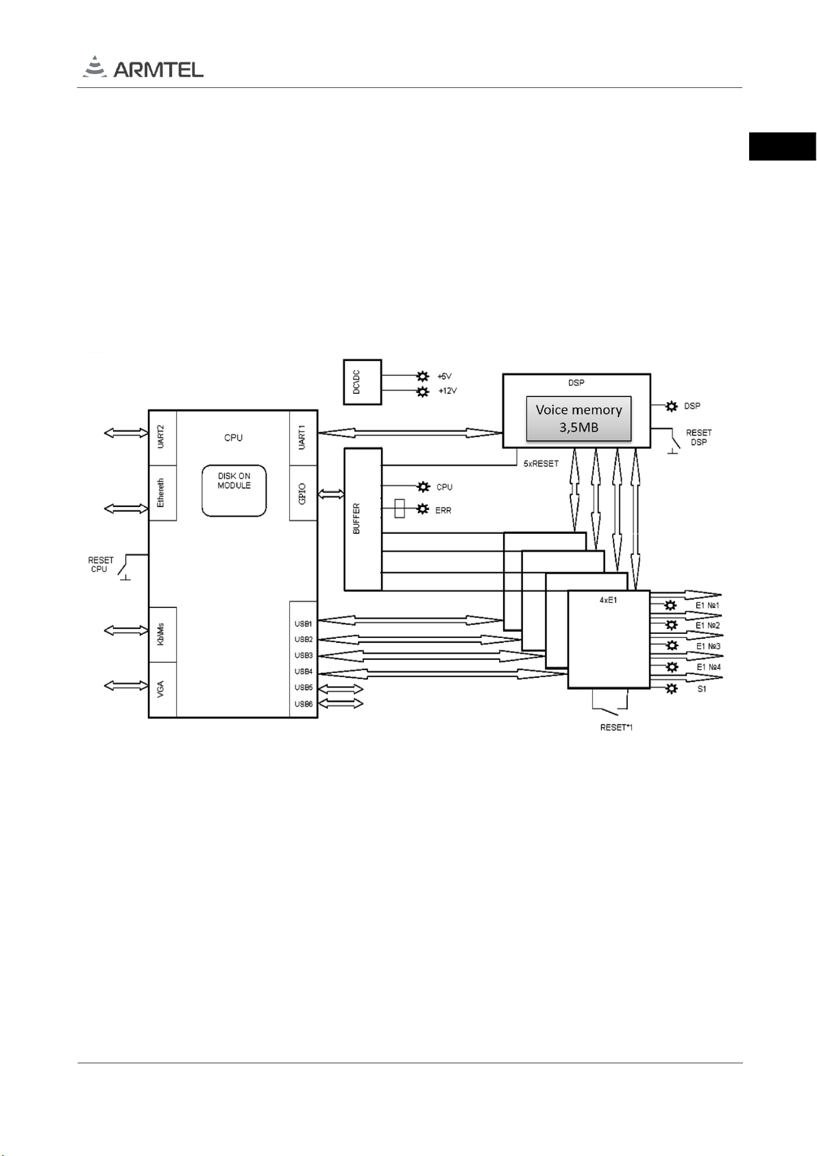
The structural diagram of DCN-2 is illustrated in Figure 2.
Figure 2 –Structural diagram of DCN-2
The diagram shows the main functional elements involved in DCN-2:
CPU processor is made on the basis of Vortex86DX-800MHz processor;
DISK ON MODULE –IDE flash-disk microSDHC-4Gb;
UART1 –RS-232 serial interface for communication with DSP;
UART2 –RS-232 serial interface for PC communication;
GPIO parallel interface for DSP hardware reset, 4E1 boards, and control of “CPU"
and "ERR" LEDs;

ENG
USB –serial interface for 4Е1 boards control;
Ethernet –RJ-45 serial interface for PC communication;
Kb/Mc –interface for keyboard and mouse connection;
VGA –interface for display connection;
DSP –signaling processor board, performs switching of speech paths,
conference organization, storing and replaying of audio information;
BUFFER –conversion circuit of LPT signal levels;
4хЕ1 –4E1 board, designed for the formation of four E1 streams. DCN-2
provides for the installation of up to four 4E1boards;
DC/DC –auxiliary power supply unit that generates 5 V, 12 V power supply for
circuit boards and modules of the product;
RESET –Reset key is designed for device hardware reset.

ENG
The external appearance of DCN-2 with the removed enclosure cover and four installed
4E1 modules is shown in Figure 3.
1 –board 1 4E1; 2 –board 2 4E1; 3 –board 3 4E1; 4 –board 4 4E1;
5 - board DSP; 6 –module CPU
Figure 3 –External appearance of DCN-2 with the removed enclosure cover and four installed
4E1 modules
1
2
3
45
6

ENG
Figure 4 shows the external appearance and overall dimensions of the board of the
DSP signaling processor.
Figure 4 –Board DSP

ENG
Connectors, controls, and indications
Figure 5 illustrates the fragment of the DCN-2 front panel with the соntrols.
Figure 5 –Fragment of DCN-2 front panel
Note –All the LEDs used on the front panel are two-colored (red/green).
Figure 5 shows:
S1…S4» – 4E1 board status indicators;
«1…16» – E1 ports status indicators (of the devices connected to the product);
RST –CPU hardware reset key;
CPU –CPU status indicators; CPU1 (upper) CPU status, CPU2 (lower) reserved;
DSP –DSP status indicators, DSP1 (upper) DSP status, DSP2 (lower) DSP
communication status with CPU;
ERR –upper status indicator of internal source of error;
ERR –lower status indicator of external source of error;
FUSE PWR –status indicator of DCN-2 system fuse, the main supply voltage is
48V;
«+5V», «+12V» – indicators of DC secondary control voltage + 5 V and +12 V
(secondary power supply +12V is not used);
«RS-232» – RS-232 interface additional connector (not used);
«Ethernet» – RJ-45 interface connector for remote access to DCN-2 from PC.
ENG
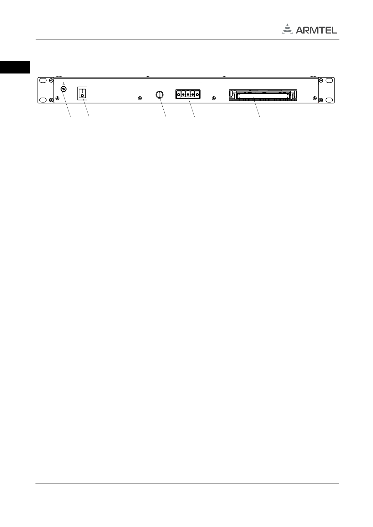
Figure 6 shows the DCN-2 rear panel with switching elements.
1 –screw for connecting functional grounding; 2 –power on/off; 3 –power fuse 48 V (2A);
4 –three-contact connector «-48 GND 0V» for the supply voltage 48 V; 5 –96-contact
connector of DIN41612 for the connection cable of DCN-2
Figure 6 –Rear panel of DCN-2
PWR IN
-48 GND 0V
Fuse
T 2A 16 x E1 Ports
PWR
2 3 451

ENG
1.1.5 Marking
A bilingual nameplate (in Russian and English) is pasted on the left side surface of the
DCN-2 enclosure.
The nameplate contains the following information:
name, trademark, and reference information of the manufacturer;
name and designation of the product;
permissible operating temperature range;
degree of protection provided by enclosures (IP code);
commercialization mark for products on the market of Customs Union member
states;
mark III electrical safety class according to GOST IEC 61140-2012;
special waste disposal mark;
product serial number;
date of manufacture.
The serial number of the product, the license number of the software, and the QR code
from the software kit are indicated on the front panel of the product.
The serial number, software license number, and QR code from the software package
are unique for each product.

ENG
1.1.6 Packing
The DCN-2 with the assembly kit and documents, which come with the supply package,
is packed in a consumer package (cardboard box) according to GOST 23088-80.
A label in Russian language and English language is glued onto the consumer package,
said label containing the following inscriptions and symbols:
product name and description;
name, trademark, and reference information of the manufacturer;
handling symbols according to GOST 14192-96 and CU TR 005/2011;
commercialization mark for products on the market of Customs Union member
states;
serial number and date of manufacture.
The package is made according to the drawings of the product manufacturer and
enables storage of the DCN-2, provided requirements set in Section 5 are met.
For shipment of the DCN-2 from the manufacturer, consumer package contents are
placed in the package place, which ensures protection from mechanical damage, direct
ingress of atmospheric precipitation, dust, and solar radiation during transportation.
This manual suits for next models
1
Table of contents
Other ARMTEL Switch manuals


Popular Switch manuals by other brands


KTI Networks
KTI Networks KSD-103-A Series installation guide

Smartwares
Smartwares SH4-90162 instruction manual

ABB
ABB Zenith ZTG Series quick start guide

Topspin
Topspin 120/Cisco SFS 7000 quick start guide

Gembird
Gembird CAS-241 user manual

ABB
ABB i-bus KNX 6108/02-500 Installation instructions & operating manual

schmersal
schmersal ZF 232 Series operating instructions

Planet
Planet FNSW-1601 user manual

Key Digital
Key Digital KD-HDMI2X1 operating instructions

Domosys Corporation
Domosys Corporation E-PBM-0100-A user manual

Advantek Networks
Advantek Networks ANS-24RV user manual

EtherWAN
EtherWAN OttoE TF100 Sereis installation guide