ARO SLE15B-1 O-Q User manual

ARO
OPERATOR’S MANUAL
Tool Products INCLUDING: OPERATION,INSTALLATlON & MAINTENANCE
SECTION
M31
MANUAL
4
Released:
3-01-96
MODELS SLE15B-1 O-Q, SLE15B-20-Q SLE26B-3-Q
SLE26B-7-Q SLE26B-12-Q, STE40B-7-Q, SPE15B-10-Q,
SPE15B-20-Q, SPE26B-3-Q, SPE26B-7-Q, SPE26B-12-Q
AND SPE40B-7-Q ELECTRIC SCREWDRIVERS
IMPORTANT SAFETY INFORMATION ENCLOSED.
READ THIS MANUAL BEFORE OPERATING TOOL.
FAILURE TO OBSERVE THE FOLLOWING WARNINGS COULD RESULT IN INJURY.
Always wear eyeprotection when operating or .
performing maintenance on this tool.
Power tools can vibrate in use. Vibration,
repetitive motions, or uncomfortable positions may
beharmful to your hands and arms. Stop using
any tool if discomfort, tingling feeling or pain .
occurs. Seekmedical advice before resuming use.
Keep work area clean. Clutteredareasandbenches
invite injuries. .
Consider work area environment. Don’t expose
powertoolsandchargersto water. Keepwork area .
well lighted. Do not usetool in presenceof flam-
mableliquids or gases.
Keep bystanders away. Do notpermit unauthorized
personnelto operatethis tool.
Store idle tools. Whennot in use,tools shouldbe
storedin adry andsecuredarea.
Don’t force tool. It will do thejob betterandmore
safelyattheratefor which it wasintended. .
Usethe right tool. Do not forceasmalltool or
attachmentto dothejob of aheavy-duty tool.
Don’t usetool for purposenot intended. .
For example- don’t usescrewdriverfor adrill.
Dressproperly. Do not wearlooseclothing or
jewelry. They canbecaughtin moving parts. Rubber
glovesandnon-skid footweararerecommendedwhen
working outdoors. Wearprotective hair covering to
contain long hair.
Securework. Useclampsor aviseto hold work.
Operatorsoften needboth handsto performjob
functions.
Don’t overreach. Keepproperfooting, balance,and
afirm grip on thetool atall times.
Maintain tools with care. Keeptools sharpand
cleanfor betterandsaferperformance. Follow
instructions for lubricating andchangingaccessories.
Inspecttool cordsperiodically andif damaged,have
themrepairedby anauthorizedservicefacility. In-
spectextensioncordsperiodically andreplaceif dam-
aged. Keephandlesdry, clean,andfreefrom oil and
grease.
Removeadjusting keysand wrenches. Formhabit
of checkingto seethat keysandadjustingwrenches
areremovedfrom tool beforeturning it on.
Avoid unintentional starting. Don’t carry tool with
finger on switch.
(continued on page 2)
The useof other than genuine ARO replacement parts may result in safety hazards, decreasedtool performance, and
increasedmaintenance, and may invalidate all warranties.
ARO is not responsible for customer modification of tools for applications on which ARO wasnot consulted.
Repairs should bemadeonly by authorized trained personnel. Consult your nearestARO Tool Authorized Servicenter.
It is the responsibility of the employer to place the information in this manual into the hands of the operator.
For parts and service information, contact your local ARO distributor.
AROTool&HoistProducts
Ingersoll-RandCompany
ARO
© Ingersoll-Rand Company 1996
Printed in U.S.A.
Part of worldwide Ingersoll-Rand

(Continued from page I)
Stay alert. Watchwhatyou aredoing. Usecommon
sense.Do not operatetool whenyou aretired.
Check damagedparts. Beforefurther useof thetool,
aguardor otherpart thatis damagedshouldbe
carefully checkedto determinethat it will operate
properly andperformits intendedfunction. Checkfor
alignmentof moving parts,binding of moving parts,
breakageof parts,mounting, andanyotherconditions
thatmayaffectits operation. A guardor otherpart that
is damagedshouldbeproperly repairedor replacedby
anauthorizedservicecenterunlessotherwiseindicated
elsewherein this operationmanual.
Have defective switches replaced by an authorized
service center.
Do not usethe tool if the switch doesnot turn it on
and off.
- GROUNDING INSTRUCTIONS
Thetool shouldbegroundedwhile in useto protectthe
operatorfrom electric shock. The tool is equippedwith a
three-conductorcordandthree-prong grounding-type plug
to tit thepropergrounding-type receptacle.Thegreen(or
greenandyellow) conductorin thecordis thegrounding
wire. Neverconnectthegreen(or greenandyellow) wire
to alive terminal. If your unit is for useon lessthan 150V,
it hasaplug thatlooks like that shownin Figure A.
An adapter(seeFigure B) is availablefor connecting
FigureA-type plugs to 2-prong receptacles.Thegreen
coloredrigid grounding strapmustbeconnectedto a
permanentgroundsuchasto aproperly groundedoutlet
box asshownin figure C.
COVER OF
ADAPTER OUTLET BOX
FIGURE B
(Dwg. TPD446-1)
Extension Cords
Make sureyour extensioncordis in goodcondition. When
using anextensioncord,besureto useoneheavyenoughto
carry thecurrentyour product will draw. An undersized
cord will causeadropin line voltageresulting in lossof
powerandoverheating.
Tableshowsthecorrectsizeto usedependingon cord
length andnameplateampererating. If in doubt,usethe
next heaviergage. The smallergagenumber,theheavier
thecord.
Total Length of Cord in Feet
0-25 25-50 51-100 101-150
AWG
18 16 I 16 14
PLACING TOOL IN SERVICE
OPERATIONS CAUTIONS
all othermodels-
l
Wheneverchangingabit, makecertainthe
Forward/ReverseSwitch is in the “OFF” position and
thetool is unplugged.
l
Do not allow chemicalssuchasacetone,benzene,
thinner, ketone,trichloroethylene or othersimilar
chemicalsto comein contactwith thescrewdriver
housingasdamagewill result.
l
Do not dropor abusethescrewdriver.
l
Do not adjustthetorquesettinghigher than7 on the
TorqueScale.
Duy cycle: 1200rpm and2000rpm models-
MAX 0.5sec.“ON”
MIN 3.5SEC.“OFF”
MAX. .8sec.“ON”
MIN 3.5sec.“OFF”
l
Do not tighten morethan900tapping screws(size:2
mm,length: 4 mm)perhour.
. Do not usethis screwdriverfor tightening wood
screws.
l
Do not operatetheForward/ReverseSwitch whenthe
motoris running.
l
Wheneveratool is not being used,movethe
Forward/ReverseSwitch to the“OFF” position and
unplug thescrewdriver.
2

MAINTENANCE SECTION
TORQUE ADJUSTMENT
Toadjustthetorqueon thesescrewdrivers,proceedas
follows:
1.
2.
Determinethetorqueoutput of thetool by checkinga
tightenedfastenerwith atorquewrench.
Increaseor decreasethetorqueoutput by rotating the
SpringAdjusting Ring (37or 39). RotatingtheRing
clockwise to ahigher numberon theTorqueScale
increasetorqueoutput while rotating theRing
counterclockwise to alower numberdecreasesthe
3. Checktheadjustmentwith atorquewrench. A number
of factorswill affecttorqueoutput from onejob to
another. Final torqueadjustmentshould bemadeatthe
job through aseriesof gradualincrease.. Always start
below thedesiredtorqueandwork upward.
l
Do not drop or abusethe tool.
. Whenever a tool is not being used,position the
Power Switch to the “OFF”’ position and unplug the
power cord.
torqueoutput.
DO NOT ATTEMPT TO REPAIR
THIS TOOL.
The numbers from zero to sevenon the Torque
Scaleare referencenumbers only and are not an
indication of actual torque output.
All repairsandmaintenanceof this tool andits cord
mustbeperformedby anauthorizedservicecenter.
Contactyour local ARO distributor.
SAVE THESE INSTRUCTIONS. DO NOT DESTROY.
MODELIDENTIFICATION
High Torque
l
Power: 115VAC
l
Cable Length: 8 ft. Straight
l
Sound: 69 dBA
l
Reversible: Yes
S P E 15B - IO - Q
SCREWDRIVER P Push-To-Start ELECTRIC
L Lever Start MOTOR
T Trigger Start
TORQUE
(max.approx.)
(in-;:bs.)
26
40
SPEED l/4” hex
3=300 rpm
7=700 rpm Quick Change
lO=lOOOrpm
12=1200 rpm
20=2000 rpm
(Dwg. TPD1860)
3

MAINTENANCE SECTION
Dimensions for Series SLE/SPE/STE Electric Screwdrivers
TYPICAL FOR : SPE15B-IO-Q
SPEISB-20-O
SPE26B-3-Q
SPE26B-7-0
SPE26B-12-O
SPE40B-7-0
(Dwg. TPC655)
TYPICAL FOR : SLEISB- ,0-k eo 2.o
SLEISB-20-0
SLE26B-3-O
SLE26B-7-Q
SLE26B-12-O
STE40B-7-0
(Dwg. TPC656)
4

MAINTENANCE SECTION
Handle for Series SLE/SPE/STE ELectric Screwdrivers
(Dwg. TPC657)
5

MAINTENANCE SECTION

12
4
6
8
9
11
12
13
14
15
16
17
18
19
20
21
22
23
24
25
26
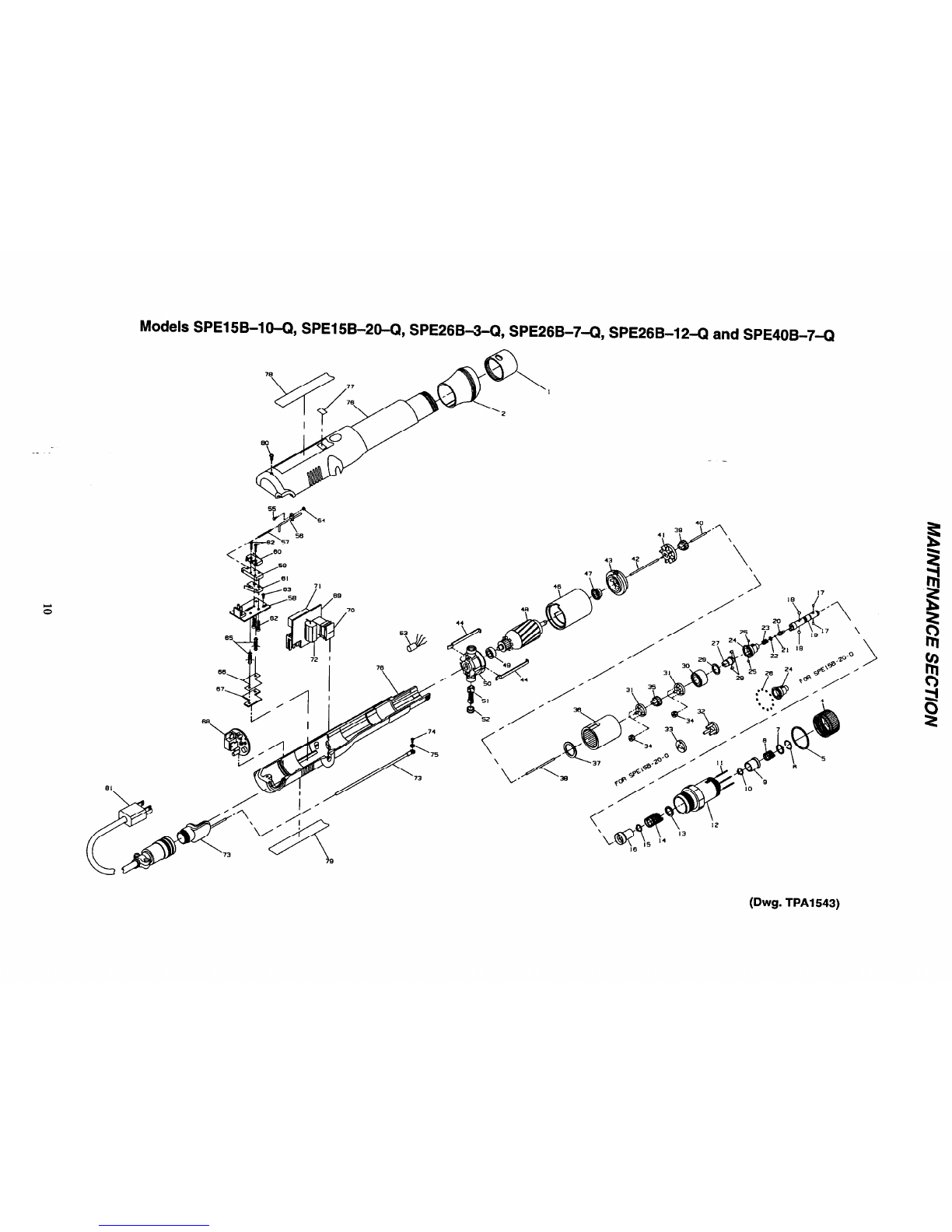
Models SLE15B-10-Q SLE15B-20-Q SLE26B3-Q, SLE26B-7-Q SLE26B-12-Q
and STE40B-7-Q Electric Screwdrivers
PART NUMBER FOR ORDERING
Retainer Coupling ................................
StraightFlange(Standardon STE4ON-7-Q) ...........
SlantedFlange(Standardon all others) ................
Clutch Adjusting Ring .............................
Indicator Ring ...................................
Bit RetainerRetaining Ring (Front) ..................
Bit RetainerCollar ...............................
Bit RetainerSpring ...............................
Bit RetainerSleeve ...............................
Bit RetainerRetaining Ring .........................
Clutch Adjusting Pin (3) ...........................
Clutch Housing Assembly ..........................
FrontShim ......................................
Rear Shim.......................................
Clutch SpringPlate ...............................
Clutch Spring
for SLElSB-l0-Q ..........................
for SLElSB-20-Q ..........................
for SLE26B-3-Q, SLE26B-74 and
SLE26B-12-Q .............................
for STE40B-7-Q ...........................
TaperRing Retaining Ring .........................
TaperRing Assembly
for SLE15B-20-Q ..........................
for SLElSB-10-Q, SLE26B-3-Q
SLE26B-7-Q andSLE26B-12-Q .............
for STE40B-7-Q ...........................
Bit Retaining Ball (.094dia.) (2) ....................
Pilot CamBall (.156dia.) (4) .......................
Bit Holder Assembly ..............................
Pilot ...........................................
Pilot Ball (.062dia.) ...............................
CamGuide
for SLE15B-20-Q ..........................
for all others ...............................
Cam Guide Ball (.156dia.) .........................
CamGuide Bearing Ball (23) (078”dia.)
(forSLE15B-20-Q) ..............................
SLE15B-125
EP4007N-123
EP4007N-124
EP4007N-582
EP4007N-682
EP4007N-683
EP4007N-585
EP4007N-931
EP4007N-930
EP4007N-584
EP4007N-416
EP4007N-580
EL4007N-623
EL4007N624
EP4007N-623
EP1510N-583
EP1520N-583
EP2607N-583
EP4007N-583
EP4007N-584
EP152ON-588
EP2607N-588
EP4007N-588
ROOOB-263
2U-696
EP4007N-586
EP4007NA08
EP4007N-422
EP1520N-681
EP4007NA-681
2U-696
EL1520N-510
27
28
29
30
31
33
34
35
36
38
PART NUMBER FOR ORDERING
Cam for SLE26B-3-Q andSTE40B-7-Q ............
for all others ...............................
CamRoller (2) ...................................
SpindleWasher
for SLE15B-20-Q ..........................
for all others ...............................
SpindleBearing ..................................
Spindle/GearHead(2)
for SLElSB-l0-Q, SLE26B-3-Q and
SLE26B-7-Q ..............................
for SLE26B-12-Q ..........................
for STE40B-7-Q ...........................
GearHead(for SLEl5B-20-Q) .....................
GearHeadSpacer(for SLE15B-20-Q) ...............
PlanetGear
for SLE15B-10-Q ..........................
for SLE15B-20-Q ..........................
for SLE26B-3-Q ...........................
for SLE26B-7-Q ...........................
for SLE26B-12-Q ..........................
for STE40B-7-Q ...........................
GearHeadPinion Gear
for SLEl5B-10-Q andSLEl5B-20-Q ..........
for SLE26B-3-Q ...........................
for SLE26B-7-Q ...........................
for SLE26B-12-Q ..........................
for STE40B-7-Q ...........................
GearCase
for SLElSB-l0-Q ..........................
for SLE15B-20-Q, SLE26B-3Q, SLE26B-12-Q
andSTE40B-74 ..........................
for SLE26B-7-Q ...........................
GearCaseShield .................................
Clutch Pilot Rod “I” (2.26” long) ....................
EP4007N-581
EP1510N-581
EP4007N-587
EL152ON-509
EP4007N-509
EP4007N-510
EP2607N-216
EP2612N-216
EP4007N-216
EP1520N-216
EP1520N-108
EPlSl0N-10
EP1520N-10
EP2603N-10
EP2607N-10
EP2612N-10
EP4007N-10
EP1510N-17
EP2603N-17
EP2607N-17
EP2612N-17
EP4007N-17
EP1510-37
EP4007N-37
EP2607N-17
EP4007N-207
EP4007N-435
*
Not illustrated.

39
40
41
42
00
43
44
46
47
48
49
50
51
53
54
55
*
Models SLE15B-10-Q SLE15B-20-Q SLE26B-3-Q SLE26B-7-Q SLE26B-12-Q
and STE40B-7-Q Electric Screwdrivers (Continued)
PART NUMBER FOR ORDERING PART NUMBER FOR ORDERING
FanPinion Gear
for SLEl5B-10-Q ....................
for SLEl5B-20-Q andSLE26B-3-Q .....
for SLE26B-7-Q .....................
for SLE26B-12-Q ....................
for STE4OB .........................
FanPilot Rod “G” (.385” long) ..................
Fan for SLEl5B-20-Q ....................
for all other ..........................
Motor Pilot Rod “J” (2.71” long) .................
Motor Assembly
for SLE26B-3-Q .....................
for SLEl5B-10-Q andSLE26B-7-Q .....
for SLE15B-20-Q ....................
for SLE26B-12-Q andSTE4OB-7-Q .....
Front End Plate ..........................
Motor AssemblySpring (2) .................
Field
for SLEl5B-10-Q, SLE26B-3-Q and
SLE268-7-Q ........................
for SLE15B-20-Q, SLE26B-12-Q and
STE40B-7-Q ........................
Front Armature Bearing ....................
Armature
for SLE26B-3-Q .....................
for SLEl5B-10-Q andSLE26B-7-Q .....
for SLE15B-20-Q . ...................
for SLE26B-12-Q andSTE4OB-7-Q .....
RearArmature Bearing ....................
RearEnd Plate ...........................
BrushAssembly (includes 10pieces) .............
Brush Cap(2) ............................
MotorCoil ..................................
AdjustingScrewNut ..........................
PilotRod Adjusting Screw .....................
*Notillustrated.
t
EP1510N-18
EP2603N-18
EP2607N-18
EP2612N-18
EP4007N-18
EP4007N-436
EL1525K-52
EP4007N-52
EP4007N-437
EP2603N-A53
EP2607N-A53
EP1520N-A53
EP4007N-A53
EP4007N-11
EP4007N-98
EP2607N-54
EP4007N-54
EP4007N-24
EP2603N-53
EP2607N-53
EP152ON-53
EP4007N-53
EP4007N-22
EP4007N-12
EP4007N-BP
EP4007N-25
EP4007N-594
EP4007N-593
EP4007N-592
56
57
58
59
60
61
62
63
65
66
67
68
69
70
*
71
72
73
74
75
76
77
78
79
PilotRod “D” ................................
PilotRod Spring ..............................
MicroswitchCircuit Board .....................
SwitchPlate .................................
Shut-offSwitch ..............................
StartSwitch .................................
SwitchScrew(12 mm) (4) ......................
SwitchBaseScrew(5 mm) (2) ..................
SwitchBaseSpacer(2) ........................
Isulating Film ...............................
BrushLight Circuit Board ......................
ControllerAssembly ..........................
ReverseSwitch Circuit BoardAssembly ...........
ReverseSwitch Circuit Board ...............
ReverseSwitch ...........................
ReverseSwitch Rocker ....................
Capacitor ...............................
Resistor ................................
ReceptacleAssembly ..........................
Ground Screw...............................
Gound ScrewWasher .........................
HousingAssembly
for SLElSB-10-Q ....................
for SLElSB-20-Q ....................
for SLE26B-3-Q .....................
for SLE26B-7-Q .....................
for SLE26B-12-Q ....................
for STE4OB-7-Q .....................
Throttle Lever ...........................
Throttle Spring ...........................
Throttle Lever Pin ........................
Housing Package .........................
t
EP4007N-438
EP4007N-595
ET4007N-220
ET4007N-221
EP4007N-223
ET4007N-222
EP4007N-224
EP4007N-226
EP4007N-225
EP4007N-227
EP4007N-228
EP4007N-424
EP4007N-A229
EP4007N-229
EP4007N-329
EP4007N-330
EP4007N-230
EP4007N-231
EP4007N-44
EP4007N-42
EP4007N-43
SLE15B-l0-A40
2
SLEl5B-20-A40
SLE26B-3-A40
SLE26B-7-A40
SLE26B-12-A40
STE40B-7-A40
EL4007N-273
EL4007N-274
EL4007N-275
EP4007N-40

80
81
82
83
84
*
*
W
Models SLE15B-10-Q SLE15B-20-Q SLE26B-34, SLE26B-7-Q SLE26B-12-Q
and STE40B-7-Q Electric Screwdrivers
PART NUMBER FOR ORDERING
BrushLight Cover ...................... EP4007N-45
Nameplate
for SLEl5B-10-Q .................. SLE15B-10-301
for SLE15B-20-Q .................. SLE15B-20-301
for SLE26B-3-Q ................... SLE26B-3-301
for SLE26B-7-Q ................... SLE26B-7-301
for SLE26B-12-Q .................. SLE26B-12-301
for STE4OB-7-Q ................... STE4OB-7-301
WarningLabel ......................... EP4007N-99
Housing Screw(packageof 10) ............ EP4007N-41
PowerCord (8’; straight) ..................... EP4007N-239-8
TorqueAdjusting Wrench .................... EP4007N-516
SuspensionBail
for STE40B-7-Q (fits Pistol Grip) ..... EP4007N-366
for all others(fits tool) ............... EP4007N-365
* Not illustrated.
PART NUMBER FOR ORDERING*-\
t
Microswitch Adjusting WrenchPackage
............
PistolGrip Assembly ...........................
PowerCord (12’; straight) .......................
PowerCord (6’; coiled) ..........................
Test Brush (ll5V). ............................
Switch AdjustmentGauge(for high torquemodels)
GearCaseJig (for high torquemodels) .............
HardwarePackage(includes illustrated items6, 10,
17, 19[2],44[2], 52[2], 54,55, 62[4], 63[2], 66,
74,75,77,78and83 ...........................
MaintenanceLabel .............................
English ..............................
French ..............................
German..............................
Spanish..............................
ES60T-MSW
STE40B-48
EP4007N-239-12
EP4007N-230-C6
EP4007N-TB-115
EPl5l0N-SG
EP1510N-J37
E14007N-HP
EP4007N-302
EP4007N-302F
EP4007N-302G
2
EP4007N-302s

Models SPElSB-10-Q SPE15B-20-Q SPE26B-3-Q, SPE26B-7-Q SPE26B-12-Q and SPE40B-7-Q
(Dwg. TPAl543)

Models SPE15B-10-Q SPE15B-20-Q SPE26B-3-Q SPE26B-7-Q SPE26B-12-Q and SPE40B-7-Q
1
*
2
4
5
6
7
8
9
10
11
12
13
14
15
16
17
18
19
20
21
22
23
24
25
26
PART NUMBER FOR ORDERING PART NUMBER FOR ORDERING
t
RetainerCoupling ...........................
StraightFlange(Standardon SPE4OB-7-Q) .......
SlantedFlange(Standardon all others ...........
Clutch Adjusting Ring ........................
Indicator Ring ..............................
Bit RetainerRetaining Ring (Front) .............
Bit RetainerCollar ...........................
Bit RetainerSpring ..........................
Bit RetainerSleeve ..........................
Bit RetainerRetaining Ring ....................
Clutch Adjusting Pin (3) ......................
Clutch HousingAssembly .....................
Clutch SpringPlate ..........................
Clutch Spring
for SPElSB-l0-Q ..................
for SPEl5B-20-Q ..................
for SPE26B-3Q, SPE268-7-Q,
andSPE26B-12-Q .................
for SPE4OB-7-Q ...................
TaperRing Retaining Ring ....................
TaperRing Assembly
for SPE15B-20-Q ..................
for SPEl5B-10-Q, SPE26B-3-Q,
andSPE26B-12-Q .................
for SPE4OB-7-Q ...................
Bit RetainingBall (.094dia.) (2) ................
Pilot Cam Ball (.156dia.)(4) ..................
Bit Holder Assembly .........................
Pilot ......................................
Pilot Ball (.062dia.) ..........................
Pilot PushSpring Washer. .....................
Pilot PushSpring ............................
CamGuide
for SPE15B-20-Q ..................
for all others .......................
Cam Guide Ball (.156dia.) ....................
CamGuide Bearing Ball (23) (for SPEl5B-20-Q) .
* Not illustrated.
SLE15B-125
EP4007N-123
EP4007N-124
EP4007N-582
EP4007N-682
EP4007N-683
EP4007N-585
EP4007N-931
EP4007N-930
EP4007N-584
EP4007NA16
EP4007N-580
EP4007N-623
27
28
29
EP1510N-583
EP152ON-583
32
33
34
EP2607N-583
EP4007N-583
EP4007N-584
EP1520N-588 35
EP2607N-588
EP4007N-588
ROOOB-263
2U-696
EP4007N-586
EP4007N-408
EP4007N-422
EP4007N-421
EP4007N-420
36
EP1520N-681
EP4007N-681
2U-696
EP1520N-510
37
38
Cam for SPE26B-3-Q andSPE4OB-7-Q ....
for all others .......................
CamRoller (2) ..............................
SpindleWasher
for SPEl5B-20-Q ..................
for all others .......................
SpindleBearin .............................
Spindle/Gear Head(2)
for SPE15B-10-Q, SPE26B-3-Q and
SPE26B-7Q ......................
for SPE26B-12-Q ..................
for SP4OB-7-Q ....................
GearHead(for SPEl5B-20-Q) ................
GearHeadSpacer(for SPE15B-20-Q) ...........
PlanetGear
for SPEl5B-10-Q (6) ...............
for SPEl5B-20-Q (3) ...............
for SPE26B-3-Q (6) ................
for SPE4OB-7-Q(6) ................
for SPE26B-12-Q (6) ...............
GearHeadPinion Gear
for SPEl5B-10-Q andSPE15B-20-Q . .
for SPE26B-3-Q ...................
for SPE26B-7-Q ...................
for SPE26B-12-Q ..................
for SPE4OB-7-Q ...................
GearCase
for SPEl5B-10-Q ..................
for SPE15B-20-Q SPE26B-3-Q,
SPE26B-12-Q andSPE40B-7-Q ......
for SPE26B-7-Q ...................
GearCaseShield ............................
ClutchPilot Rod “I” (2.26” long) ...............
EP4007N-581
EP1510N-581
EP4007N-587
EP152ON-509
EP4007N-509
EP4007N-510
EP2607N-216
EP2612N-216
EP4007N-216
EPl520N-216
EP1520N-108
EP1510N-10
EP1520N-10
EP2603N-10
EP4007N-10
EP2612N-10
EP1510N-17
EP2603N-17
EP2607N-17
EP2612N-17
EP4007N-17
EP1510N-37
EP4007N-37
EP2607N-37
EP4007N-207
EP4007N-135

Models SPE1B-10Q, SPE15B-20-Q, SPE268-3-Q, SPE26B-7-Q, SPE26B-12-Q and SPE40B-7-Q
39
40
41
42
43
44
46
47
48
49
50
51
52
53
54
55
PART NUMBER FOR ORDERING
FanPinion Gear
for SPEl5B-10-Q ....................
for SPEl5B-20-Q andSPE26B-3-Q .....
for SPE26B-7-Q .....................
for SPE26B-12-Q ....................
for SPE4OB-7-Q .....................
FanPilot Rod“G” (.385” long) ................
Fan ......................................
for SPE15B-20-Q ....................
for all others .........................
MotorPilot Rod“J” (2.71” long) ...............
MotorAssembly
for SPE26B-3-Q .....................
for SPE15B-20-Q ....................
for SPE15B-1O-QandSPE26B-7-Q .....
for SPE26B-12-Q andSPE4OB-7-Q .....
Front EndPlate ..........................
Motor AssemblySpring (2) .................
Fieldfor SPEl5B-10-Q, SPE26B-3-Q and
SPE26B-7-Q ........................
for SPE15B-20-Q, SPE26B-12-Q and
SPE40B-7-Q ........................
Front Armature Bearing ....................
Armature
for SPE26B-3-Q .....................
for SPE15B-20-Q ....................
for SPEl5B-10-Q andSPE26B-7-Q .....
for SPE26B-12-Q andSPE4OB-7-Q .....
RearArmature Bearing ....................
RearEndPlate ...........................
Brush Assembly(includes 10pieces) .........
BrushCap(2) ............................
MotorCoil ................................
AdjustingScrewNut ........................
PilotRodAdjusting Screw ...................
t
EP151ON-18
EP2603N-18
EP2607N-18
EP2612N-18
EP4007N-18
EP4007N-436
EP4007N-52
EL1525K-52
EP4007N-52
EP4007N-437
EP2603N-A53
EP1520N-A53
EP2607N-A53
EP4007N-A53
EP4007N-11
EP4007N-98
EP4007N-11
EP2607N-54
EP4007N-54
EP4007N-24
EP2603N-53
EP1520N-53
EP2607N-53
EP4007N-53
EP4007N-22
EP4007N-12
EP4007N-BP
EP4007N-25
EP4007N-594
EP4007N-593
EP4007N-592
56
57
58
59
60
61
62
63
65
66
67
68
69
70
*
71
72
73
74
75
76
PART NUMBER FOR ORDERING’-\
SwitchPilot Rod“D” ........................
PilotRodSpring ............................
Microswitch Circuit Board ...................
SwitchPlate ...............................
Shut-off Switch ............................
Start Switch ...............................
SwitchScrew(12 mm) (4) ....................
SwitchBaseScrew(5 mm) (2) ................
SwitchBaseSpacer(2) ......................
InsulatingFilm .............................
BrushLight Circuit Board ....................
ControllerAssembly ........................
ReverseSwitch Circuit BoardAssembly .........
ReverseSwitch Circuit Board ...............
ReverseSwitch ...........................
ReverseSwitch Rocker ....................
Capacitor ...............................
Resistor ................................
ReceptacleAssembly ........................
Ground Screw.............................
GroundScrewWasher .......................
HousingAssembly
for SPEl5B-10-Q ...................
for SPEl5B-20-Q ...................
for SPEl5B-3-Q ....................
for SPE26B-7-Q ....................
for SPE26B-12-Q ...................
for SPE40B-7-Q ....................
Housing Package .........................
t
EP4007N-438
EP4007N-595
EP4007N-220
EP4007N-221
EP4007N-223
EP4007N-222
EP4007N-224
EP4007N-226
EP4007N-225
EP4007N-227
EP4007N-228
EP4007N-424
EP4007N-A229
EP4007N-229
EP4007N-329
EP4007N-330
EP4007N-230
EP4007N-231
EP4007N-44
EP4007N-42
EP4007N-43
SPE15B-lO-A40
SPE15B-20-A40
SPE26B-3-A40
SPE26B-7-A40
SPE26B-12-A40
SPE40B-7-A40
EP4007N-40
* Not illustrated.

Models SPE15B-10-Q, SPE15B-20-Q SPE26B-3-Q SPE26B-7-Q SPE26B-12-Q
and SPE40B-7-Q (Continued)
PART NUMBER FOR ORDERING
77 BrushLight Cover . . . . . . . . . . . . . . . . . . . .
78 Nameplate
for SPE15B-10-Q ..............
for SPE15B-20-Q ..............
for SPE26B-3-Q ...............
for SPE26B-7-Q ...............
for SPE26B-12-Q ..............
for SPE4OB-7-Q ...............
WarningLabel .......................
Housing Screw(packageof 10) ..........
PowerCord (8’; straight) ..................
TorqueAdjusting Wrench .................
SuspensionBail
for SPE40B-74 (fits Pistol Grip) .
for all others(fits tool) ...........
* Microswitch Adjusting WrenchPackage
......
79
80
81
*
*
EP4007N-45
SPE15B-10-301
SPE15B-20-301
SPE26B-3-301
SPE26B-7-301
SPE268-12-301
SPE4OB-7-301
EP4007N-99
EP4007N-41
EP4007N-239-8
EP4007N-516
EP4007N-366
EP4007N-365
ES60T-MSW
PART NUMBER FOR ORDERING
t
Pistol Grip Assembly . . . . . . . . . . . . . . . . . .. . .
PowerCord (12’; straight) . . . . . . . . . . . . . . . ..
PowerCord (6’; coiled) . . . . . . . . . . .. . . . . . . .
TestBrush (115V) . . . . . . . . . . . . . . . . . . . . . . .
Switch AdjustmentGauge(for high torque
models)................................
GearCaseJig (for high torquemodels) . . . . . . .
HardwarePackage(includes illustrated items6,
10, 15, 17[2],44[2], 52[2], 54,55, 62[4], 63[2],
66,74,75and 80 . . . . . . . . . . . . . . . . . . . . .. .
MaintenanceLabel
English . . . . . . . . . . . . . . . . . . . . . . .
French . . . . . . . . . . . . . . . . . .. . . . .
German.......................
Spanish.......................
STE40B-48
EP4007N-239-12
EP4007N-230X6
EP4007N-TB115
EPl5l0N-SG
EP1510N-J37
EP4007N-HP
EP4007N-302
EP4007N-302F
EP4007N-302G
EP4007N-302s
* Not illustrated.

MAINTENANCE SECTION
DISASSEMBLY
Always wear eyeprotection when operting or per-
forming maintenance on this tool. Always turn off
the electrical supply and disconnect the electrical
cord before installing, removing or adjusting any
accessoryon this tool, or before performing any
maintenance on this tool.
Disassembly of the Housing
1. Unplug thePowerCord (81or 84) from the wall
socket. Unscrewtheconnectionring andsetthecord
aside.
2. UnscrewtheRetainerCoupling (1) andremovethe
Flange(2).
This is a left-hand thread.
3. Lay thetool onthe workbenchwith the Brush Light
Plate(77or 80) sidedown andremovetheHousing
Screw(80 or 83)using a#l phillips screwdriver.
4. Insert athin bladescrewdriverinto the two notches
andcarefully pry thetwo halvesof theHousing Pack-
age(76) apart.
For Throttle Lever Start Models, removethe
Throttle Lever (76), Throttle Spring (77) andThrottle
Lever Pin (78).
Disassembly of the Clutch Housing and Gear
Case
1.
2.
3.
4.
5.
6.
7.
8.
9.
10.
11.
12.
SeparatetheSpindle/GearHeadsandremovethe
GearHeadPinion Gear(35) andPlanetGears(34).
Fit thetwo notchesattherearof the GearCaseinto
theGearCaseJig partno. EPl510N-J37.
(Referto Dwg. TPD1820)
clockwise
(Dwg. TPDl820)
Using athin bladescrewdriver,removetheFront Bit
RetainerRetaining Ring (6) from theBit Retainer
Sleeve(9). RemovetheBit RetainerCollar (7), the
Bit RetainerSpring (8) andtheBit RetainerSleeve.
Removethetwo Bit Retaining Balls (17 or 19)from
theBit Holder Assembly(19 or 21) by tapping the
Housingon thework surface.
UnscrewtheClutch Adjusting Ring (4) andremove
thethreeClutch Adjusting Pins (11).
Using external snapring pliers, removetheBit Re-
tainer Retaining Ring (10).
Using a29mmwrenchon the flats of the Clutch
Housing, unscrewandremovetheClutch Housing
from theGearCase.
Tilt theClutch Housing (12), GearCase(36) and
Motor Assemblyupwardslightly andturn theGear
Caseuntil theGround Screw(74) shows.
This is a left-hand thread.
Besure to hold the Motor Assembly and Gear
Casetogether. Rough handling may damagethe
Fan Pilot Rod (40) in the Fan (41).
Using aphillips screwdriver,removetheGround
ScrewandtheGround ScrewWasher(75).
RemovetheClutch Housing andGearCasefrom the
Housing. Whenremoving theGearCasefrom the
Housing,hold theGearCaseShield (37) sothat the
Gearsdo not fall out.
RemovetheFan(41) andtheFanPinion Gear(39).
RemovetheFanPilot Rod (40).
The Fan Pilot Rod is ceramic. Do not mishandle
or drop.
RemovetheGearCaseShield anddrop thetwo
Spindle/GearHeads(31)from the GearCase.
13.
14.
15.
16.
17.
18.
RemovetheClutch Spring Plate(13 or 15)andthe
Clutch Spring (14or 16).
RemovetheTaperRing Retaining Ring (15 or 17).
RemovetheBit Holder Assemblyandseparateit
from theTaperRing Assembly (16 or 18).
Removethetwo Pilot CamBalls (18 or 20), thePilot
PushSpring (23), thePilot PushSpring Washer(22)
andthePilot (20 or 22) from the Bit Holder Assem-
bly.
For Throttle Lever Start Models, removetheFront
Shim(13) andtheRearShim (14) first. Then remove
theTaperRing Retaining Ring. SeparatetheTaper
Ring Assemblyfrom theBit Holder. Removethetwo
Pilot CamBalls andthePilot (22) from theBit Hold-
erAssembly.
RemovetheClutch Pilot Rod (38) andtheCam
Guide (24). Removethetwo CamGuide Balls (25)
from theGuide.
14

MAINTENANCE SECTION
19.
20.
21.
Lift theGearCasefrom theGearCaseJig andpush
theSpindleBearing (30) andCam(27) from the
Case.
Lift theCamfrom theSpindleBearing andremove
theCamRollers (28).
SlidetheSpindleWasher(29) from the SpindleBear-
ing.
Cleaning and Inspection of the Tool
1.
2.
3.
4.
5.
6.
7.
8.
9.
10.
11.
Cleanall of themechanicalpartsin anapprovedsafe-
ty solution in awell-ventilated area. Inspectfor
damageor wear.
InspecttheFan. If thefour comersof thehole are
worn, replacetheFan.
InspecttheFanPinion GearandFanPilot Rod. If
they aredamagedor cracked,replacethem.
If thetaperon thePilot is worn, replacethePilot and
thetwo Pilot CamBalls.
InspecttheCamGuideBalls. If they areworn, re-
placethem.
InspecttheCamGuide. If its holesareworn, replace
it.
InspecttheTaperRing Assembly. If theinternal ta-
peris worn, replaceit.
InspecttheCamRollers. If they areworn, replace
them.
InspecttheSpindleWasher.If thesurfaceis worn,
replaceit.
InspecttheSpindleBearing. If it doesnot rotate
smoothly,replaceit.
InspecttheGearsandtheGearCase.If theteethare
worn, replacethem.
Disassembly of the Electrical Components
1.
2.
3.
RemovetheReverseSwitch Circuit Board(69) from
theHousing.
Do not touch any circuit paths if using pliers.
LoosentheReceptacleAssembly(73).
Using a#0phillips screwdriver,removethetwo
Switch BaseScrews(63) mountedon theMicro-
switch Circuit Board(58).
The Switch BaseScrewsare coatedwith thread
adhesive. Unscrew gradually to prevent damage
to the threads.
4. RemovetheMotor AssemblyandtheController As-
sembly(68) from theHousing Packagewhile holding
bothof themtogether.
Becareful not to damagethe Motor Pilot Rod (42).
5. ToremovetheController Assembly,pull thethree-
pin connectorfrom theReverseSwitch Circuit Board.
6. Removethetwo-pin connectorfrom theMicroswitch
Circuit Board.
7. Using needlenosepliers, removethethreewiresfrom
theShut-off Switch (60).
8.
9.
10.
11.
12.
13.
14.
15.
16.
17.
18.
19.
20.
21.
22.
23.
Becareful not to damagethe Shut-off Switch
Terminals.
SettheController Assemblyaside.
GrasptheMicroswitch Circuit Boardusing needle
nosepliers andsqueezetheendsof thetwo white
Switch BaseSpacers(65).
Using needlenosepliers, squeezetheSwitch Base
SpacersandremovetheInsulating Film (66).
Using thepliers, removetheSwitch BaseSpacers
from theBrush Light Circuit Board.
Removethetwo Shut-off Switch Screws(62).
Removethetwo StartSwitch Screws(62).
RemovetheSwitch Plate(59) andtheSwitch Pilot
Rod(56) from theSwitch Plate.
Inspectthetip of theSwitch Pilot Rod. If it is bentor
worn, replaceit.
ChecktheShut-off Switch for continuity. Replaceit
if defective.
ChecktheStartSwitch (61) for continuity. If it is
defective,desolderandremoveit from theMicro-
switch Circuit Board.
If theBrushLight Circuit Boardis defective,desolder
andremovetheredandblue wires.
If thecomponentson theReverseSwitch Circuit
Boardaredamagedor defective,desolderandremove
theredandblue wires.
If theReverseSwitch (70) is damaged,desolderand
replace.
Using anOhmmeter,checktheResistor(72) on the
ReverseSwitch Circuit Board. Readingsshouldbe
20Ohm.
If theCapacitor(71) is damaged,desolderandre-
placeit.
If theMotor Coil (53) is damaged,desolderthered
andblue motor leadsandreplacethecoil.
15

MAINTENANCE SECTION
Disassembly of the Motor
1.
2.
3.
4.
5.
6.
7.
8.
9.
10.
11.
RemovetheBrush Caps(52) from theRearEnd Plate
(50). Using apick, catchtheterminal of theBrush
Assembly(51) andpull it out of theRearEnd Plate.
Do not damagethe copper wires of the Brush As-
sembly. Reinstall the Brushes asthey were re-
moved unlessthey are replaced.
Removetheinsulation tapearoundtheMotor.
Using athin bladescrewdriver,removetheMotor
AssemblySprings(44) by inserting the screwdriver
betweentheSpringsandtheRearEnd Plateandpry-
ing upward.
RemovetheRearEnd PlateandtheFront End Plate
(43) from theField (46).
PushingtheArmature (48) towardtheFanside,re-
movetheArmature from theField.
Do not damagethecommutatoror the windings of
theArmature. Hold therotor, not the commutator.
RemovetheMotor Pilot Rod from theArmature and
inspectit. If it is worn, replaceit.
RemovetheFront ArmatureBearing (47) andthe
RearArmatureBearing (49) from theArmature and
inspectthem. If they do not rotatesmoothly,replace
them.
InspecttheArmature,Field andEndPlates. Usea
pieceof fine cloth to wipe awaycontamination. For
excessbuild up, spraywith contactcleanerandbrush
if necessary.
Tocleanthecommutatoron theArmature, spraywith
contactcleanerandbrushif necessary.
Using atester,inspectthecommutator. Replacethe
Armatureif necessary.
ASSEMBLY
Assembly of the Motor Housing
1. Install theFront ArmatureBearing (47) andtheRear
ArmatureBearing(49) to theArmature shaftends.
2. Apply greaseto bothendsof theMotor Pilot Rod
(42) andinsertit into thecenterhole of theMotor
Assembly.
3. InserttheArmaturethrough the notchedendof the
Field (46).
Becareful not to damagethe commutator or the
windings. Hold the rotor, not the commutator
when assembling.
4. Install theRearEnd Plate(50) to the notchedendand
theFront EndPlate(43) to the Field.
5. Snapthetwo Motor AssemblySprings(44) over the
notchesof theRearEnd Plateandthe Front End
Plate.
6. Insert theBrush Assemblies(51) into thebrushhold-
ersof theRearEnd Plate. Be surethe tabon the
Brush Assemblyslidesinto thenotch in theholder.
7. Screwon theBrush Caps(52).
8. Wraponelayer of 3M #56 insulation tapearound
theMotor Assembly.
9. For Throttle Lever Start Models, put two addi-
tional stripsof insulation tape,oneupon theother,
onto theBrushLight Circuit Board (67) sideof the
Motor Assembly. This insulatestheareabetweenthe
groundwire andthe Field.
Assembly of the Electrical Components
1.
2.
3.
4.
Solderthered andblue wires to theBrush Light Cir-
cuit Board.
SoldertheReverseSwitch (70) andtheResistor(72).
Using shrink tubing 5mmlong asspacers,solderthe
Capacitor(71) into place. Solderthe redandblue
wiresto theReverseSwitch Circuit Board
(69).
SoldertheStartSwitch (61) onto theMicroswitch
Circuit Board(58).
Insert theSwitch Pilot Rod (56) into thehole in the
Switch Plate(59). (Referto Dwg. TPDl819).
PILOT ROD ASSM. SCREWS
BRAKE SWITCH
BRAKE SWITCH
START SWITCH
START SWITCH
START SWITCH
INSULATING FILM
BRUSH LIGHT LED
(Dwg. TPDl819)
5. Mount the Switch Platewith thePilot Rodonto the
StartSwitch by depressingthe StartSwitch lever with
thePilot Rod. Insert thePilot Rod into theslot in the
Microswitch Circuit Boardandalign the Switch Plate
on top of theStartSwitch. Insert the two Switch
BaseScrews(63) from the bottomof theMicroswitch
Circuit Boardinto the Switch Plate. Tighten the
Screwsto 1.6KG-cm.
6. Mount theShut-off Switch (60) onto theSwitch Plate
with thetwo Switch Screws(62). Tighten the screws
to 1.6KG-cm.
16

MAINTENANCE SECTION
7.
8.
9.
10.
11.
12.
Position theInsulating Film (66) onto thebackof the
BrushLight Circuit Board. Insert thetwo Switch
BaseSpacers(65) through theInsulating Film and
into theholesof theCircuit Board.
Install theBrushLight Circuit Boardonto the backof
theMicroswitch Circuit Boardby inserting thetwo
SwitchBaseSpacersinto theholesin theCircuit
Board.
Besure that the Brush Light LED is toward the
motor sideof the circuit board.
Using needlenosepliers, install thethreeconnectors
from theController Assembly(68) onto the Shut-off
Switch.
Make sure to connect the correct color wire to the
proper terminal. Refer to the wiring diagram to
insure that all wires are installed properly.
Install thetwo-pin connectorfrom theController
AssemblyontotheMicroswitch Circuit Board.
Install thethree-pin connectorfrom theController
AssemblyontotheReverseSwitch Circuit Board.
Run thegroundwire aroundthe Switch BaseSpacers
andbetweentheMicroswitch Circuit Boardandthe
BrushLight Circuit Board.
(Referto Dwg. TPD1818).
ROUTE OF GROUNDING WIRE
MICRO SWITCH
nil
CIRCUIT BOARD FOR
BRUSH LIGHT
SPACERS
(Dwg. TPD1818)
13.
14.
15.
Bring theMotor AssemblyandMicroswitch Circuit
Boardtogetherby inserting theMotor Pilot Rod into
thehole in theMotor shaftandthen settingboth into
theHousingPackage(76).
For Throttle Lever Start Models, lay the ground
wire betweentheMotor andtheHousing Package.
Install thetwo SwitchBaseScrewsandtighten to 1.6
KG-cm.
Install theController Assemblyinto its groovein the
Housing. Placetheground wire into the notch in the
Controller Assemblyandalign this notch with thetab
in theHousing
16.
17.
18.
19.
Install theReverseSwitch Circuit Boardinto the two
groovesin theHousing.
Install theReceptacleAssembly(73) into theHous-
ing, making suretheground wire is underneaththe
HIC. TheReceptaclecanbeinstalled in either posi-
tion.
Placetheblack andwhite Receptaclewires into the
notchin theController Assembly.
PlacetheceramicFanPilot Rod (40) into theFan
Pinion Gear(39) andthen fit the Gearinto theFan
(41). Now slide theFan(41) onto theMotor shaft.
Assembly of the Gear Caseand Clutch Housing
1.
2.
3.
4.
5.
6.
7.
8.
9.
10.
11.
12.
13.
14.
15.
16.
17.
18.
19.
Apply greaseto thePlanetGears(34), the surfacesof
theGearHeads(32) andthe teethof the GearHead
Pinion Gear(35).
AssembletheSpindle/GearHeads,theGearHead
Pinion GearandtheGearHead.
Apply greaseto all theGears.
PlacetheGearHeadonto the Spindle/GearHeads.
Apply greaseto the SpindleWasher(29).
PlacetheSpindle Washer,thenthe SpindleBearing
(30), onto theCam(27).
Apply greaseto theinner teethof the GearCase(36).
Insert theCaminto the SpindleBearing.
Hold theCamwith needlenosepliers andinsert the
entire unit into theGearCasewhile rotating theCam
andtheGearCase.
Apply greaseto thegearendof theGearCaseand
install theGearCaseShield (37).
Apply greaseto thenotchesof theCam.
PlacetheCamRollers (28) into the notcheson the
Cam.
Apply greaseto theinner surface,theholesandthe
groovesof theCamGuide (24).
Insert theCamGuide Balls (25) into the holesin the
CamGuide.
Install theCamGuide over the Cam. KeeptheCam
Balls ata90 degreeangleto theCamRollers to pre-
venttheBalls from beingpushedout.
Apply greaseto theinner surfaceof theBit Holder
Assembly(19or 21). Using arod, pushthe Pilot (20
or 22) into theBit Holder.
For Push to Start Models, insertthePilot Push
SpringWasher(22) andthePilot PushSpring (23)
into theBit Holder.
Throttle Lever Start Models do not useaPush
SpringandWasher.
Apply greaseto theholesof theBit Holder andinsert
thetwo Pilot CamBalls (18 or 20).
Apply greaseto theinner diameterandthetapered
endof theTaperRing Assembly (16 or 18). Insert
greasebetweentheball bearingthrust washerandthe
TaperRing Assembly,which areattached.Install the
TaperRing Assemblyonto the Bit Holder.
17

MAINTENANCE SECTION
20.
21.
22.
23.
24.
25.
26.
27.
28.
29.
30.
31.
32.
Install theBit Holder Assemblyonto theCamGuide
in theGearCase.
TheTaperRing Retaining Ring (15 or 17)hasa
round edgesideanda sharpedgeside. Install the
TaperRing RetainingRing, sharpedgesidefirst, into
thegrooveon the Bit Holder.
There are four grooveson the Bit Holder. The
fourth groove from the bit end is for Push to Start
Models. The third is for Throttle Lever Start
Models.
For Throttle Lever Start Models, placetheSpindle
WashersontotheBit Holder.
PlacetheClutch Spring (14or 16)andtheClutch
SpringPlate(13 or 15)over the Bit Holder.
Fit thetwo notchesattherearendof theGearCase
Assemblyinto theGearCaseJig part no.
EP151ON-J37.ScrewtheClutch Housing (12) par-
tially into theGearCase.
This is a left-hand thread.
At themiddle of theClutch Housing threads,apply
Loctite Threadlocker3Bond 1406(R)* to about
threethreads. Pushdown androtatetheBit Holder
until it engagestheCamGuide. Hold in place.
ScrewtheClutch Housing in completely.
Using anopenendtorquewrenchon the flats of the
Clutch Housing,tighten theClutch Housing to 28.5
Nm.
Apply greaseto bothendsof theClutch Pilot Rod (36
or 38)andinsert it into the GearCase.
For Throttle Lever Start Models, inspecttheclear-
anceof theBit Holder Assembly. Touchthe endof
theClutch Pilot Rodandpushon theBit Holder As-
sembly. If theClutch Pilot Rodis movedby theBit
Holder atthis time, addadditional spacers.
Install theBit RetainerRetaining Ring (l0), sharp
edgesidefirst, into thesecondgroovefrom thebit
endof theBit Holder.
Apply greaseto theholesof theBit Holder andinsert
thetwo Bit Retaining Balls (17or 19)into theholes.
Apply greaseto oneendof eachClutch Adjusting Pin
(11)andinsert the threePins into the Clutch Housing.
Apply greaseto theotherendof eachClutch Adjust-
ing Pin andthethreadsof theClutch Housing. Screw
theClutch Adjusting Ring (4) ontothe Housing.
Install theBit RetainerSleeve(9), theBit Retainer
Spring (8) andtheBit RetainerCollar (7) onto theBit
Holder.
33.
34.
35.
36.
37.
38.
Using athin bladescrewdriver,install the Front Bit
RetainerRetaining Ring (6).
UnclamptheGearCaseJig from the vise andturn it
overto removethe Clutch andGearCaseAssembly.
Hold theGearCaseShield to keeptheGearsin place.
Lift theMotor slightly andslide theGearCaseonto
theMotor with theGround Screwhole adjacentto the
ground wire.
Attach theground wire to theGearCasewith the
Ground Screw(74) andWasher(75). Tighten to 4
KG-cm.
Turn theGearCaseuntil the notch in the GearCase
matchesthetabin theHousing.
Completely insertthe groundwire into thegroove in
theHousing.
Adjusting the Brake Timing
1. Insert a.65mmthick gaugeor pin gaugebetweenthe
Pilot RodAdjusting Screw(55) headandthe Shut-
off Switch. PushtheBit Holder. The Shut-off
Switch should not click.
2. Insert a.80mmgaugeandpushtheBit Holder.
The Shut-off Switch should click.
3. Adjust thePilot RodAdjusting Screwif necessary
using thetwo adjustingspannerwrenches.
4. For Throttle Lever Start Models, thereis no need
topushtheBit Holder. Slide thegaugesbetweenthe
Pilot RodAdjusting Screwandthe Throttle Lever
(76).
Assembly of the Tool
1.
2.
3.
4
5.
6.
7.
For Push to Start Models, makesuretheground
wire is insertedin thegroove in theHousing.
For Throttle Lever Start Models, makesurethe
GroundWire is betweentheMotor Assemblyandthe
Housing.
SnaptheHousing halvestogether.
For Throttle Lever Start Models, insert the
Throttle Lever Pin (78) into theHousing. Insert the
Throttle Spring (77) into theThrottle Lever. While
compressingtheThrottle Spring, install theThrottle
Lever onto theThrottle Lever Pin. SnaptheHousing
halvestogether.
Install theHousing Screws(80 or 83)into the Hous-
ing andtighten to 4 KG-cm.
SlidetheFlange(2) onto the Housing. Screwthe
RetainerCoupling (1) onto theHousing until it clicks
into place.
Theseare left-hand threads.
Attach thePowerCord (81or 84).
18

MAINTENANCE SECTION
Testing the Tool
1. Testforward andreverseoperationby pressingthe
Bit Holder againstthework surfacewith theReverse
Switch in eachposition.
2. Tighten theClutch Adjusting Ring all theway,re-
verseit oneturn andtestfor propershutoff operation
andmaximumtorque.
3-PIN CONNECTOR
BRUSH LIGHT PIN

MAINTENANCE SECTION
TROUBLESHOOTING GUIDE
1 Screwdriverfails to rotate
(forward or reverse).
Doesthemicroswitch “click”
whenthebit is pushedrearward
onpushto startmodelsor when
thetrigger is depressedon
trigger models?
No
1. Startingmicroswitch is defective;replacethe microswitch.
2. Pilot Rod “H” is binding; clearobstructionor replaceRod.
3. Pilot Rod“G” or Pilot Rod“H” is defective;repair or replaceRod.
4. Bit Holder is binding; cleartheobstruction.
5. Incorrect Pilot Rod;checkeachrod length andplaceeachlength in
its properposition.
6. Incorrect assemblyof Clutch; checkclutch partsandballs for proper
assembly.
7. StopRing out of position; install the StopRing correctly.
Is thebrushlight turnedon? - No Brushesareworn; replacethebrushassemblies.
I
Yes
1.Defectiveplanetarygearing;replacethedefectiveparts.
2.Defectiveclutch; replacethedefectiveparts.
3.Defective motor,replacethe motor.
Are thebrushassembliesin good
condition? 1.Brushesarecracked;replacetheBrush Assemblies.
2.Commutatorworn; replacethemotor.
es
RemovetheCoupling, seperatethe
1. Motor is defective;replacetheMotor.
Brushesaredefective;replacetheBrush Assemblies.
Is therevoltageto theReverse 1.Coil is defective,replacethe Coil.
defectivesolderconnections.
1.ReverseSwitch is defective;replacetheReverseSwitch
2. Solderconnectionsdefective;resolderany defectivesolder
1. PowerCordis defective;replacethePowerCord.
2. Solderconnectionsdefective;resolderany defective solder
connections.
ReplacetheOn/Off Switch.
20
This manual suits for next models
11
Table of contents
Other ARO Power Tools manuals
Popular Power Tools manuals by other brands

Parkside
Parkside 406362 2207 Translation of the original instructions

Huck
Huck 2015 Series Instuction manual

Parkside
Parkside PAGG 4 A1 Translation of the original instructions

Bosch
Bosch GSH 11 E Repair instructions

Huskie Tools
Huskie Tools 7M Series Operator's manual

Makita
Makita TW004G instruction manual