WACKER Group M 1000 User manual

www.wackergroup.com
Internal Vibrator
M 1000
M 2000
M 3000
OPERATOR’S MANUAL
0154561en 001
0403
0154561EN


Foreword
wc_tx000001gb.fm
Engine exhaust, some of its constituents, and certain vehicle
components contain or emit chemicals known to the State of California
to cause cancer and birth defects or other reproductive harm.
1. Foreword
This manual provides information and procedures to safely operate
and maintain this Wacker model. For your own safety and protection
from injury, carefully read, understand and observe the safety
instructions described in this manual.
Keep this manual or a copy of it with the machine. If you lose this
manual or need an additional copy, please contact Wacker
Corporation. This machine is built with user safety in mind; however,
it can present hazards if improperly operated and serviced. Follow
operating instructions carefully! If you have questions about operating
or servicing this equipment, please contact Wacker Corporation.
The information contained in this manual was based on machines in
production at the time of publication. Wacker Corporation reserves the
right to change any portion of this information without notice.
All rights, especially copying and distribution rights are reserved.
Copyright 2002 by Wacker Corporation.
No part of this publication may be reproduced in any form or by any
means, electronic or mechanical, including photocopying, without
express written permission from Wacker Corporation.
Any type of reproduction or distribution not authorized by Wacker
Corporation represents an infringement of valid copyrights and will be
prosecuted. We expressly reserve the right to make technical
modifications, even without due notice, which aim at improving our
machines or their safety standards.
WARNING
HMS
ii
MADE IN
USA
87577
hplbs kW
kg
Month / Year
dB(A)
Item Number Rev. Serial Number
MENOMONEE FALLS, WI USA 53051
Model
Serial Number
Maschinen-Nummer
Número de Serie
Numéro de Série
My machine’s numbers are / Die Nummern meines Gerätes sind /
Los números de mi máquina son / Les numéros de ma machine sont :
Revision
Version
Nivel de revisión
Niveau de revision
Item Number
Artikel-Nummer
Número de referencia
Numéro de référence
Model number
Typ
Modelo
Modèle
M1000M1000
M1000M1000
M1000
00050410005041
00050410005041
0005041 101101
101101
101 50101015010101
50101015010101
5010101
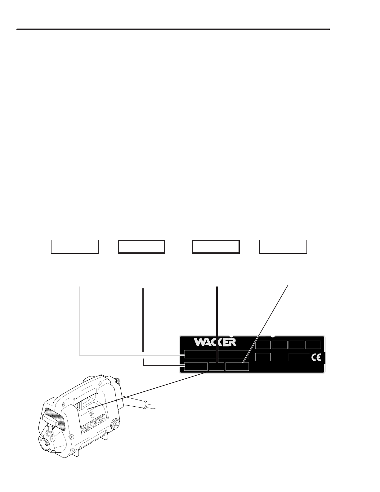
Nameplate / Typenschild / Placa de Identificación / Plaque signalétique
A nameplate listing the Model Number, Item Number, Revision, and Serial Number is attached to each unit. Please
record the information found on this plate so it will be available should the nameplate become lost or damaged. When
ordering parts or requesting service information, you will always be asked to specify the model, item number,
revision number, and serial number of the unit.
Ein Typenschild mit Typ, Artikelnummer, Version und Maschinen-Nummer ist an jedem Gerät angebracht. Die Daten
von diesem Schild bitte notieren, damit sie auch bei Verlust oder Beschädigung des Schildes noch vorhanden sind.
DerTyp,dieArtikel-Nummer,dieVersions-NummerunddieMaschinen-NummersindbeiderErsatzteilbestellung
oder Nachfragen bezüglich Service-Informationen stets erforderlich.
Una placa de identificación con el modelo, número de referencia, nivel de revisión y número de serie ha sido añadida
en cada máquina. Favor de anotar los datos en la placa en caso de que la placa de identificación sea destruida o
perdida. En todos los pedidos para repuestos necesita siempre el modelo, el número de referencia, el nivel de
revisión y el número de serie de la máquina en cuestión.
Une plaque signalétique mentionnant le modèle, le numéro de référence, le niveau de revision et le numéro de série
est fixée sur chaque machine. Veuillez noter les informations relevées sur cette plaque de façon àce qu’elles soient
toujours disponibles si la plaque signalétique venait àêtre perdue ou endommagée. Lorsque vous commandez des
pièces détachées ou vous sollicitez des informations auprès-vente, on vous demandera toujours de préciser
le modèle, le numéro de référence, le niveau de revision et le numéro de série de la machine.
1007SD48

1
1A-1
HMS
Operating Information 1A
Contents
1.1 Safety Information ................................................................................ 1A-2
1.2 Safety................................................................................................... 1A-3
1.3 Technical Data ..................................................................................... 1A-4
1.4 Safety & Informational Labels .............................................................. 1A-5
1.5 Label Locations .................................................................................... 1A-5
1.6 Application ........................................................................................... 1A-6
1.7 Recommended HMS Combinations ..................................................... 1A-6
1.8 Extension Cords................................................................................... 1A-7
1.9 Connecting Motor to Power Supply ...................................................... 1A-7
1.10 Assembling Head, Motor and Shaft ...................................................... 1A-8
1.11 Operation ............................................................................................. 1A-8
1.12 Periodic Maintenance ........................................................................... 1A-9
1.13 Motor Brushes...................................................................................... 1A-9
1.14 Motor Housing...................................................................................... 1A-9
1.15 Lubricating Shaft ................................................................................ 1A-10
1.16 Lubricating Head ................................................................................ 1A-10
1.17 Checking Head for Wear .................................................................... 1A-11
1.18 Troubleshooting ................................................................................. 1A-11
1.19 Wiring Schematics ............................................................................. 1A-12

1A OPERATION HMS
1A-2
1.1 Safety Information
This manual contains DANGER, WARNING, CAUTION, and NOTE callouts which must be followed to reduce the
possibility of personal injury, damage to the equipment, or improper service.
CAUTION: Used without the safety alert symbol,
CAUTION indicates a potentially hazardous situation
which, if not avoided, may result in property damage.
Note:
Contains additional
information important to a procedure.
This is the safety alert symbol. It is used to alert you to
potential personal injury hazards. Obey all safety messages
that follow this symbol to avoid possible injury or death.
DANGER indicates an imminently hazardous
situation which, if not avoided, will result in
death or serious injury.
CAUTION indicates a potentially hazardous
situation which, if not avoided, may result in
minor or moderate injury.
WARNING indicates a potentially hazardous
situation which, if not avoided, could result in
death or serious injury.
DANGER
WARNING
CAUTION

HMS OPERATION 1A
1A-3
Familiarity and proper training are required for the safe operation of this equipment! Equipment operated or serviced
improperly or by untrained personnel can be dangerous! Read all operating instructions and the safety notes below.
Familiarize yourself with the proper use of this equipment before operating it.
WARNING
Keep work area clean and free of clutter.
Keep work area well lit.
Do not allow children or people other than the opera-
tor to handle power cables, extension cords or the
equipment.
Donot allownon-essential personnelor visitorsin the
work area.
Never operate motor in areas exposed to flammable
or explosive liquids or gases! The motor brushes
spark during operating and could ignite fumes.
Don't overreach! Keep proper footing and balance at
all times. Make sure any supporting structures are
strong enough and stable enough to support your
weight and the weight of any equipment on it.
Keep hands, feet, hair and loose clothing away from
moving parts. They can be caught in moving parts.
Wear protective clothing when operating equipment.
Goggles or safety glasses will protect against eye
damage caused by flying debris.
Never carry motor by cord or pull on it to disconnect
it from receptacle. Keep cord away from heat, oil and
sharp edges.
Keep handle, and other areas where motor and shaft
are gripped, dry, clean and free from oil and grease.
Avoidunintentional starting! Don't carrymotor around
jobsite while it is connected to power source. Don't
carry motor with finger on switch.
Stay alert! Watch what you are doing. Use common
sense. Do not operate tool when you are tired.
Do not operate equipment if switch does not operate
properly.
Replace worn or damaged parts with replacement
parts designed and recommended for use by
WACKER Corporation.
Don't overload motor. An overloaded motor will over-
heat. Use only recommended head/motor/shaft com-
binations. See Table 1.
Neverallow untrainedpersonnel tooperate orservice
the equipment.
Never attach shaft to motor while it is running.
Alwayscheck thepower supplybefore runningmotor.
Using the wrong voltage supply will damage motor.
Always make sure motor switch is OFF before plug-
ging motor to power supply.
Any servicing, other than that covered in this instruc-
tion manual, should be performed by an authorized
WACKER Service Representative.
1.2 Safety
When using electric tools, basic safety precautions should always be followed to reduce the risk of fire, electric shock,
and personal injury! The guidelines following will help the user maintain operator safety.
When motor is used outdoors, use only extension
cords intended for and marked for outdoor use.
Always keep power cord away from heat, oil and
sharp edges which can damage it.
Make certain motor is in good working order and
properly grounded before starting.
Never operate motor with damaged or worn electrical
cords! When using an extension cord be sure to use
one heavy enough to carry the current load. See Table
2 for correct cable size to use.
Preventbody contactwith groundedsurfaces, suchas
pipes, metal railings, radiators and metal ductwork.
DANGER

1A OPERATION HMS
1A-4
M1000 (Green) M2000 (Yellow) M3000 (Red)
Voltage(AC/DC) V115 230 115 230 115 230
Current(Maximum) A9 4.5 15 6.5 20 10
Power Hp (kW) 1.3 (1.0) 1.3 (1.0) 2.3 (1.7) 2.0 (1.5) 3.1 (2.3) 3.1 (2.3)
Speed(No-load) rpm 15500 17500 16500
Weight lbs. (kg) 12(5.4) 13 (5.9) 18(8.1)
Motor type Universal electric motor
Frequency Hz 50/60
Phase 1
1.3 Technical Data
H25 H25S H35 H35S H45 H45S H55 H65
Diameter in. (mm) 1.0 (25) 1.0 (25) 1.4 (35) 1.4 (35) 1.8 (45) 1.8 (45) 2.3 (55) 2.5 (65)
Length in. (mm) 17.3 (440) 11.7 (295) 16.2 (410) 12.3 (310) 15.3 (385) 12.0 (305) 16.1 (410) 15.3 (385)
Weight lbs. (kg) 2.6 (1.2) 1.8 (0.9) 4.6 (2.1) 3.6 (1.6) 7.1 (3.2) 5.6 (2.5) 10.8 (4.9) 13.4 (6.0)
Compaction Dia. in. (cm) 16 (41) 14 (36) 24 (60) 22 (56) 30 (76) 28 (71) 40 (102) 48 (122)
Lubrication oz. (ml) 0.38 (10) 0.38 (10) 0.5 (15) 0.5 (15) 0.75 (22) 0.63 (19) 1.0 (30) 1.5 (44)
type SAE 80W140 synthetic oil (WACKER P/N 27238)
Sound and Vibration Measurements
The required sound specifications, per Appendix 1, Paragraph 1.7.4.f of the EC-Machine Regulations, are:
- the sound pressure level at operator’s location (LpA) = 84.7 dB(A)
-the guaranteed sound power level (LWA) = 96.4 dB(A)
Thesesound valueswere determinedaccording to ISO 3744 forthe soundpower level(LWA) andISO 6081for thesound
pressure level (LpA) at the operator’s location.
The weighted effective acceleration value, determined according to ISO 8662 Part 1, is 5.1 m/s2.
The sound and vibration measurements were obtained with the unit operating at nominal speed.
Vibrator Heads
Motors
Shafts
stfahS-EstfahS-S
E-1MSE-2MSE-4MSS-0MSS-1MSS-2MSS-3MSS-4MSS-5MSS-7MSS-9MS
htgneL)m(.tf)1(3)2(5,6)4(31)5,0(5,1)1(3)2(5,6)3(01)4(31)5(5,61)7(32)9(5,92
thgieW)gk(.sbl)4,1(3)3,2(5)3,4(01)3,2(5)3(7)5(11)7,6(51)5,8(91)5,01(32)41(13)7,71(93
noitacirbuL 08862N/P-ebuLtfahs-xelFREKCAW

HMS OPERATION 1A
1A-5
FOR SAFE OPERATION READ
OPERATOR’S MANUAL.
POUR UNE OPERATION SÛRE
LISEZ LA NOTICE D’EMPLOI.
SICHERHEITSANLEITUNGEN IN
BETRIEBSVORSCHRIFT LESEN.
PARA OPERACION SEGURA LEA
MANUAL DE OPERACION.
CAUTION
VORSICHT
PRECAUTION
PRECAUCION
1039SD19
78071-16
1.5 Label Locations
1.4 Safety & Informational Labels
This WACKER machine uses international pictorial labels where needed. These labels are described below:
Label Meaning
Read operator’s manual for machine information.
Wear eye, ear, and head protection when
operating machine.
1A OPERATION HMS
1A-6
1.6 Application
The HMS series of internal vibrators can be used over a
wide range of applications for the consolidation of con-
crete.
WACKER internal vibrators are typically used for on-site
vibration of concrete for foundations, walls, columns,
slab work, etc. Additional in-plant applications include
vibration of concrete during the production of pipes,
slabs, beams, double T columns, walls, etc.
Acceptable Combinations
Not Recommended - On small diameter shafts, motor may overspeed shaft and head. On long shafts, motor may overload.
Not compatible
a
b
c
1007SD34
1.7 Recommended HMS Combinations
)b(stfahS
E-1MSE-2MSE-4MSS-0MSS-1MSS-2MSS-3MSS-4MSS-5MSS-7MSS-9MS
htgneL)m(.tf)1(3)2(5.6)4(31)5.0(5.1)1(3)2(5.6)3(01)4(31)5(5.61)7(32)9(5.92
)c(daeH)a(rotoM
52H
0001M x x x x x x x x
0002M • • • x x x x x x x x
0003M • • • x x x x x x x x
53H
0001M x x x • •
0002M x x x
0003M x x x
54H 0002M x x x
0003M x x x
55H 0002M x x x
0003M x x x
56H 0002M x x x
0003M x x x
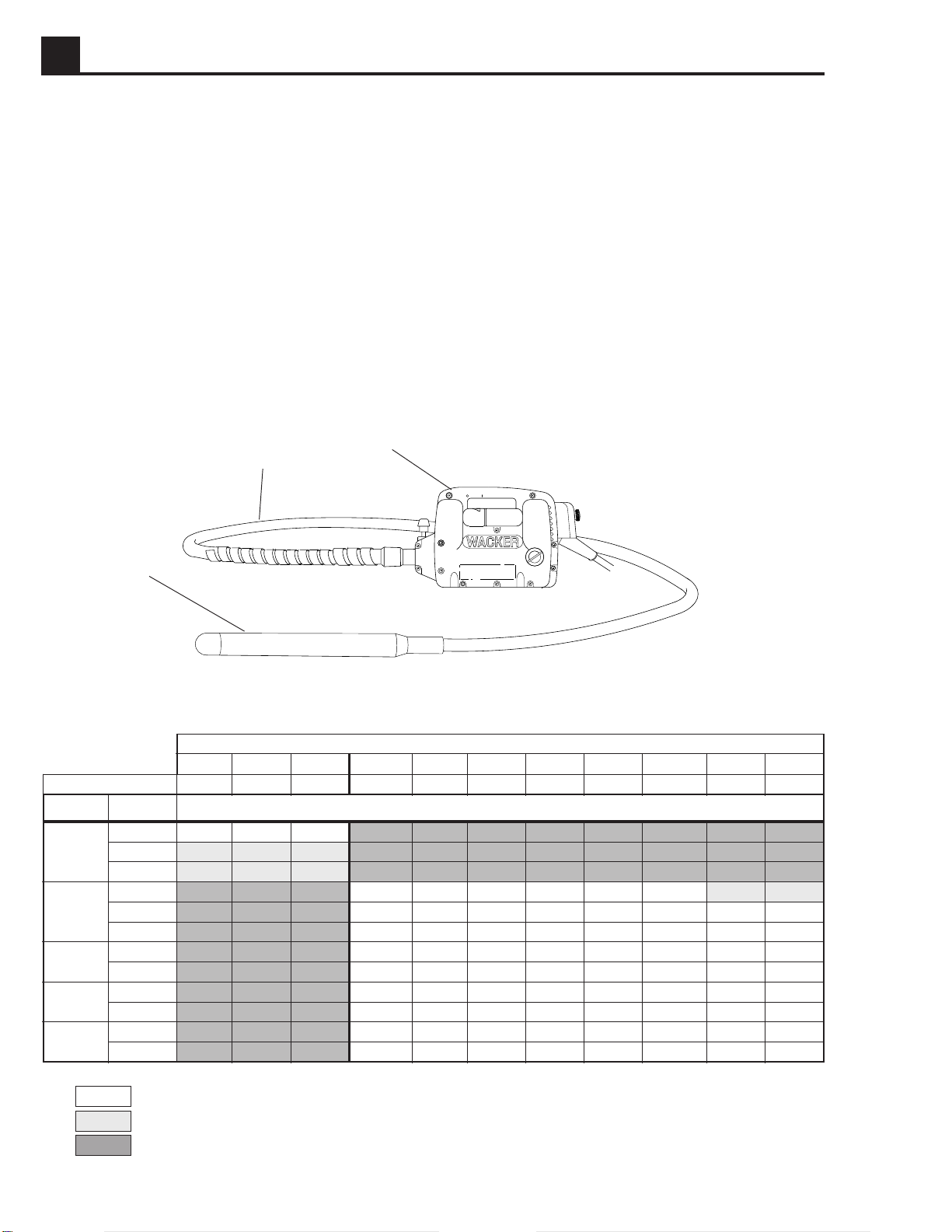
The HMS Sytem has three basic parts:
(a) motor
(b) shaft
(c) head
These three pieces can be assembled in various combi-
nations to meet job requirements. Choosing the correct
combination is important to produce good results and
protect the parts from excessive wear and damage.
Selecting too large a head/shaft combination will over-
load the motor.
Refer to Table 1 below when selecting motor, shaft, and
head combinations.
Table 1 Recommended HMS Combinations
•
x

HMS OPERATION 1A
1A-7
1.8 Extension Cords
Extensioncords areoften requiredon jobsitesto connect
the motor. When choosing an extension cord make sure
it has adequate wire size for safety. An undersized cord
willcause a dropin linevoltage resultingin a lossof power
and overheating. Refer to Table 2 when selecting exten-
sion cords. It shows the correct wire size to use depend-
ing on cord length. If in doubt, use the next heavier cord
size.
On motors being used outdoors, use extension cords
rated for outdoor use.
WARNING
MAXIMUM CORD LENGTH - ft. (m)
25' 50' 100' 150' 175' 200'
(7.5m) (15 m) (30 m) (45 m) (55 m) (60 m)
M1000 16 (1.5) 16 (1.5) 14 (2.5) 14 (2.5) 12 (4) 12 (4)
M2000 16 (1.5) 16 (1.5) 14 (2.5) 12 (4) 10 (6) 10 (6)
M3000 16 (1.5) 14 (2.5) 12 (4) 10 (6) 8 (10) 8 (10)
M1000 16 (1.5) 16 (1.5) 16 (1.5) 16 (1.5) 14 (2.5) 14 (2.5)
M2000 16 (1.5) 16 (1.5) 16 (1.5) 14 (2.5) 14 (2.5) 14 (2.5)
M3000 16 (1.5) 16 (1.5) 14 (2.5) 14 (2.5) 12 (4) 12 (4)
115V
Table 2
Minimum wire size for extension cords -
AWG (mm2)
230V
Toreduce therisk ofelectric shock,motors equipped
with3-wire grounded plugsmust beproperly ground-
ed.On thesemotors use only3-wire groundedplugs,
receptacles, and extension cords.
1.9 Connecting Motor to Power Supply
WARNING
Improper use of extension cords can cause over-
heating or create serious fire or shock hazards.
Never use worn or damaged cords!
Note:
Not all countries require the use of a three-wire
grounded plug for this piece of equipment. In these
countries, motors are equipped with a two-wire plug
which can be plugged into a standard electrical outlet.
de
1007SD13
1. Check that switch on motor is off before connecting
motor to power source.
2. Make sure power supply matches voltage require-
ments listed on motor label. Running a motor at a low
voltage will cause it to run slow. This will reduce
perfomance and may cause motor to overheat.
3. On motors equipped with a three wire grounded plug
use three-wire grounded receptacles (d) when con-
necting the motor. If a 3-wire grounded receptacle is
not available, then a grounded adapter must be in-
stalled as shown in illustration (e) to ensure a proper
ground connection.
1A OPERATION HMS
1A-8
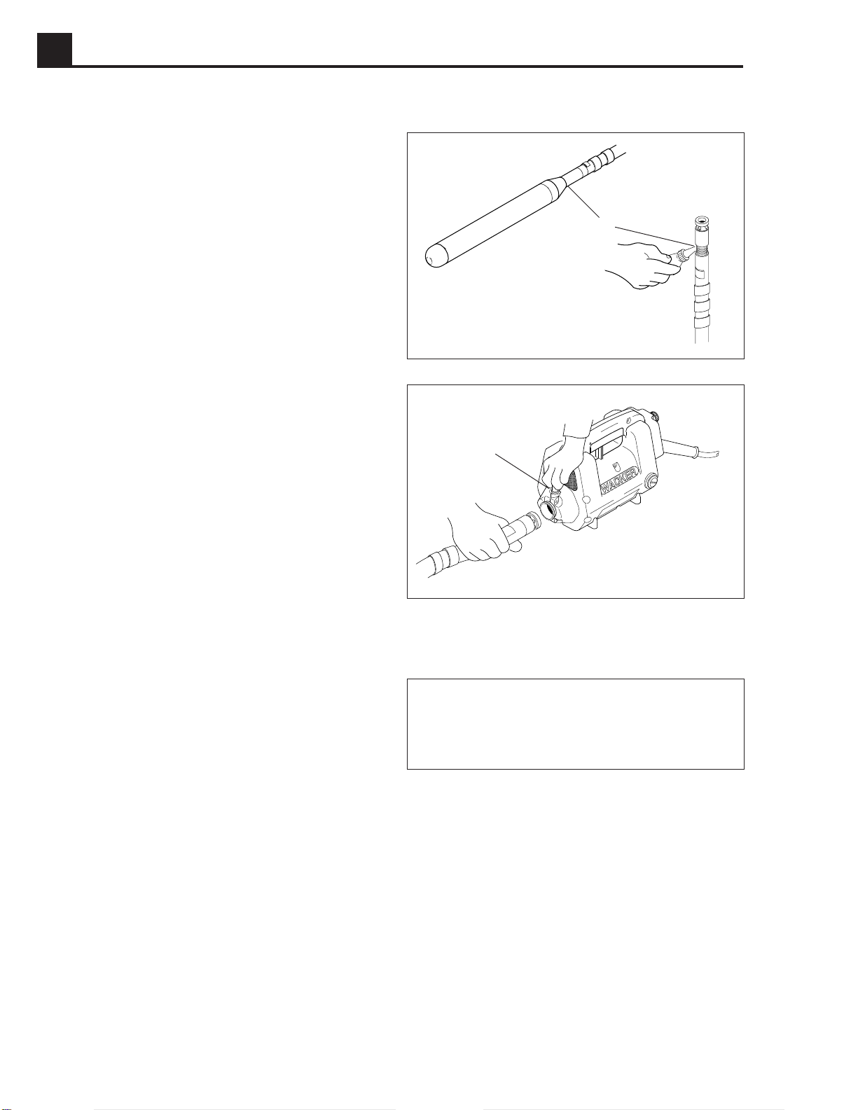
1.10 Assembling Head, Motor and Shaft
f
g
1007SD17
1007SD16
1.11 Operation
Hold head in air or place it on soft surface when starting
motor.This willprevent itfrom bouncingon hardsurfaces
which could damage bearings. During use, insert the
headquickly intothe mixand thenpull it out slowly. Rapid
removal is the main cause of poor concrete consolida-
tion. For best results submerge head completely and try
to establish a symmetrical pattern for inserting and
removing the head.
Avoidsharp bends in the shaft.This can create hot spots.
When moving around jobsite do not drag head and shaft
on ground.
Avoid touching forms and rebars when inserting head in
mix. This can transmit vibration to other areas of the mix
which may already be setting.
CAUTION: DO NOT run the motor with the head out of
the mix for long periods of time. This can cause the
bearings to overheat.
For more detailed information on the use, selec-
tion and application of WACKER equipment for
concreteconsolidation, orderWacker publication
WCW 982 “CONCRETE CONSOLIDATION”.
1. Apply pipe sealant to threads on head (c). Attach
head onto end of flexshaft (left hand thread) and
tighten using a wrench.
2. The shaft is attached to motor using a quick discon-
nect coupler. The coupler may vary depending on the
type of shaft being used. All new WACKER flexshafts
come equipped with a coupler and do not require any
additional coupling device. Refer to page 3-4 for
shafts equipped with couplers.
If you are using a shaft from another manufacturer, or
are attaching an older WACKER shaft, refer to page
3-7 to order the correct coupling to use. If a coupler
must be installed on the shaft, apply pipe sealant (f)
to threads before assembling.
3. Lubricate shaft core. See 1.15
Lubricating Shaft
.
4. To attach shaft to motor, pull adapter pin (g) on motor
up and slide coupler in place. Rotate coupler until pin
falls into coupler socket.

HMS OPERATION 1A
1A-9
1.12 Periodic Maintenance
Before Operating Inspect air filter and vent holes. Clean or replace dirty or clogged filters.
Inspect electrical cords for wear or damage. Do not use damaged cords.
Every 50 hours Inspect brushes in motor.
Every 100 hours Clean and lubricate core in shaft.
Every 300 hours Change oil in head.
1.14 Motor Housing
Clean motor housing immediately after use, using a
damp cloth to remove dust or concrete. Inspect rear air
filter, front screen, and vents on motor housing to make
sure they are open. Replace or clean clogged air filter
before operating motor to prevent overheating.
Toclean rearfilter: screw outknob andremove cover(d)
from motor. Remove filter (e) and wash in warm, soapy
water. Allow filter to dry completely before using.
1.13 Motor Brushes
To protect the motor, the brushes are designed to auto-
matically shut off the motor if they become too short. If the
motorstops during operation,the brushesmay needto be
replaced. To avoid having the brushes shut down the
motorunexpectedly, inspect brushesevery 50hours and
replace them when necessary. Always replace both
brushes at the same time.
To inspect or replace brushes:
1. Remove brush caps (a) from both sides of motor.
2. Pull brushes (b) out and measure length. Install new
brushes if length (c) is less than 3/8" (10 mm) long. If
brushes are still long enough, place them back in
motor. Make sure they are installed in the same
positions they were removed, to avoid arcing.
3. Break in new brushes by running motor for about 5
minutes with no shaft attached.
ca
b
1007SD06
d
e
1007SD05

1A OPERATION HMS
1A-10
f
g
1.15 Lubricating Shaft
Remove wire core (f) from shaft casing and wipe with a
clean cloth.
Apply a liberal amount of flex-shaft grease to the entire
lengthof the core by hand(g). Insertcore intocasing and
rotate it. Repeat this procedure several times.
CAUTION: DO NOT try to force the casing full of grease.
A tightly packed casing will put a heavy load on the motor
and could cause it to overheat.
CAUTION: DO NOT clean casing or core with solvents.
Excess solvent on casing or core may cause grease to
break down, resulting in damage to shaft.
h
1007SD15
1007SD14
1.16 Lubricating Head
The bearings in the head are lubricated with oil. To
extend bearing life, change oil in head every 300 hours
of operation.
To change oil:
Place head in a vise and remove tip from casing. If
necessary, add a couple of small spot welds (h) on tip to
provide a better grip for wrench. Drain old oil from casing
and add correct quantity of new oil. Refer to section 1.3
Technical Data
. Apply pipe sealant to threads on tip and
attach it tightly on casing.
Note:
In the interests of environmental protection, place
a plastic sheet and a container under the machine to
collect any liquid which drains off. Dispose of this liquid
in accordance with environmental protection legislation.
Use only SAE 80W140 synthetic oil or equivalent.
CAUTION:DO NOT overfill. Too muchoil in the head will
overload the motor.

HMS OPERATION 1A
1A-11
1.17 Checking Head for Wear
Periodically measure the outside diameter of the head
casing (a) in the area of most noticeable wear.
Replace head if measured diameter is less than the
minimum wear diameter.
NEW MINIMUM
DIAMETER WEAR DIAMETER
in. (mm) in. (mm)
H25 1.00 (25) 0.88 (22)
H35 1.38 (35) 1.25 (32)
H45 1.75 (44) 1.63 (41)
H55 2.25 (57) 2.13 (54)
H65 2.50 (64) 2.38 (60)
PROBLEM REASON
Motor does not start. 1. Open circuit breaker or blown fuse on power supply.
2. Brushes are worn too short. Replace.
3. Switch on motor bad or wire connections loose.
Motor runs at normal speed 1. Air filter, screen, or vents clogged, blocking air flow.
but overheats. 2. Too much grease in shaft.
3. Too much oil in head.
Motor runs at slow speed 1. Line voltage too low.
and overheats. 2. Extension cord too small.
3. Head/shaft combination too large.
4. Shaft not lubricated, core running dry.
5. Head bearings binding. Inspect and replace.
6. Rotor in motor rubbing.
7. Motor bearings failed. Inspect and replace.
Motor noisy 1. Worn brushes. Brushes installed incorrectly.
2. Worn motor bearings.
3. Rotor in motor rubbing.
1.18 Troubleshooting
a
1008SD06

1A OPERATION HMS
1A-12
W
B
L
L
B
Y
2
45
W
61
3
B
7
W
B
B
Y
2
45
W
61
3
B
W
B
7
1.19 Wiring Schematics
M1000 M2000 M3000
* NO GROUND WIRE
115V 5843 6305 5845
7159
7653
230V 5041 6551* 5800
230V 5494 5432
5495
M1000 M2000
230V 6590
M3000
1SWITCH
2STATOR
3ROTOR
4LH BRUSH
5RH BRUSH
6RFI CAPACITOR
7INDUCTION COIL
B- BLACK or BROWN
G- GREEN or GREEN W/
YELLOW STRIPE
Y- YELLOW
W- WHITE or BLUE
1SWITCH
2STATOR
3ROTOR
4LH BRUSH
5RH BRUSH
6RFI CAPACITOR
7INDUCTION COIL
B- BLACK or BROWN
G- GREEN or GREEN W/
YELLOW STRIPE
L- BLUE
Y- YELLOW
W- WHITE or BLUE
1039SD16
1039SD17
NOT USED ON 6551
1023SD06
W
B
B
2
45
W
1
3
G
W
1SWITCH
2STATOR
3ROTOR
4LH BRUSH
5RH BRUSH
B- BLACK or BROWN
G- GREEN or GREEN W/
YELLOW STRIPE
W- WHITE or BLUE

EC - CONFORMITY CERTIFICATE
EG-KONFORMITÄTS ERKLÄRUNG
CE-CERTIFICADO DE CONFORMIDAD
CERTIFICAT DE CONFORMITÉDE LA CEE
WACKER CORPORATION - MENOMONEE FALLS, WISCONSIN USA
hereby certify that the construction equipment specified hereunder
bescheinigt, daßdas Baugerät
certifica que la máquina de construcción
atteste que le matériel
1. Category - Art - Categoría - Catégorie
2. Make - Fabrikmarke - Marca - Marque
3. Type - Typ - Tipo - Type
4. Type serial number of equipment / Gerätenummer innerhalb Typenserie-Nummer
Número de serie de la máquina / Numéro dans la série du type de matériel
has been produced in accordance with the following standards
in Übereinstimmung mit folgenden Richtlinien hergestellt worden ist
ha sido fabricado en conformidad con las siguientes normas
est produit conforme aux dispositions des directives européennes ci-après
EMC 89/336/EEC
EN 60555
EN 55014
MSD 89/392/EEC
91/368/EEC
93/44/EEC
HD 400
IEC 745
File certificate carefully
Bescheinigung bitte sorgfältig aufbewahren
Conservar certificado cuidadosamente
Conserver certificat soigneusement
QM1-3000
WACKER CORPORATION
N92 W15000 Anthony Avenue Menomonee Falls, Wisconsin
53052-9007 USA (262) 255-0500 Fax (262) 255-0550
○○○○○○○○○○○○○○○○○○○○○○○○○○○○○○○○○○○
Internal Vibrator
Innenvibrator
Vibrador Interno
Vibrateur Interne
WACKER
M1000/230V
M2000/115V
M2000/230V
M3000/230V
0005494, 0007653, 0005495,
0006590
WACKER CORPORATION
William Lahner Robert Motl

This manual suits for next models
2
Table of contents
Other WACKER Group Power Tools manuals


