SteelMax BM-20 plus User manual

The tools of innovation.
15335 E. Freemont Drive, Centennial, CO 80112
1–87STEELMAX, FAX 303 –690 –9172
www.steelmax.com [email protected]
OPERATOR’S MANUAL
B
BM
M-
-2
20
0
p
pl
lu
us
s
BEVELING MACHINE

Contents
1. GENERAL INFORMATION............................................................................................... 3
1.1. Application................................................................................................................. 3
1.2. Technical data............................................................................................................ 3
1.3. Dimensions................................................................................................................ 4
1.4. Design ....................................................................................................................... 5
1.5. Equipment included ................................................................................................... 6
2. SAFETY PRECAUTIONS.................................................................................................. 7
3. STARTUP AND OPERATION........................................................................................... 9
3.1. Adjusting the bevel angle and width........................................................................... 9
3.2. Operating..................................................................................................................10
3.3. Replacing the cutting inserts.....................................................................................12
3.4. Replacing the milling cutters .....................................................................................14
4. SPARE AND WEARING PARTS......................................................................................15
5. ACCESSORIES...............................................................................................................16
5.1. 0° guide set for facing plates.....................................................................................16
5.2. Guides for beveling pipes..........................................................................................17
5.3. Guide for beveling round plates ................................................................................19
5.4. Cutting tools..............................................................................................................20
6. WIRING DIAGRAM..........................................................................................................21
7. EXPLODED DRAWINGS AND PARTS LISTS.................................................................22
8. DECLARATION OF CONFORMITY.................................................................................26
9. WARRANTY CARD..........................................................................................................27

BM-20 plus
BM-20 plus Operator’s Manual
3
1. GENERAL INFORMATION
1.1. Application
The BM-20 plus is a beveling machine designed to bevel carbon steel. The machine
can bevel plates at an angle of 15–60° and with the bevel width of up to 21 mm
(13/16″).
When equipped with accessories, the machine allows you to face plates, bevel
round plates, and bevel pipes with outer diameters of 150–300 mm (6–12″) or 300–
600 mm (12–24″).
1.2. Technical data
Voltage
1~ 220–240 V, 50–60 Hz
1~ 110–120 V, 50–60 Hz
Power
1600 W (for 50 Hz)
1800 W (for 60 Hz)
Rotational speed
2780–3340 rpm (at 230 V)
2740–3290 rpm (at 115 V)
Protection level
IP 20
Protection class
I
Milling speed
550 m/min (1800 ft/min, for 50 Hz)
650 m/min (2200 ft/min, for 60 Hz)
Maximum bevel width (b)
21 mm (13/16″, Fig. 1)
Bevel angle (ß)
15–60° (Fig. 1)
Vibration level
Machine harmful for health.
Take periodic breaks during operation.
Weight
20.5 kg (45 lbs)
Fig. 1.Bevel dimensions; maximum bevel width depending on the angle
β
15°
30°
45°
60°
b
21 mm
20.5 mm
21 mm
20.5 mm

BM-20 plus
BM-20 plus Operator’s Manual
4
1.3. Dimensions
446 mm (17.6″)
315 mm (12.4″)
323 mm (12.7″)
BM-20 plus
BM-20 plus Operator’s Manual
5
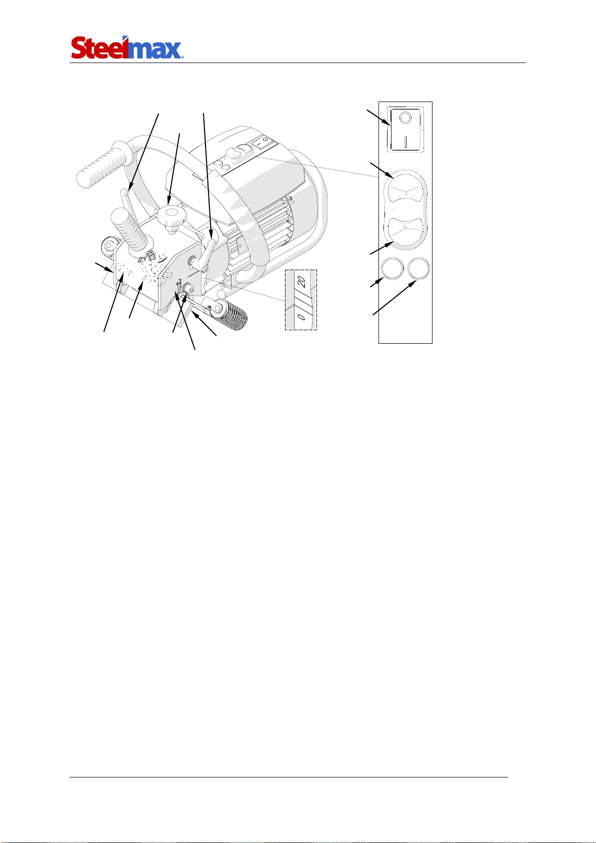
1.4. Design
Guide set
Depth
knob
Bevel width
scale
Bevel angle scale
Bevel angle lock
screws
Depth lock
levers
Power
switch
START
STOP
Motor lamp
Overload
lamp
Milling
cutters
Cov
er of
the
millin
g
cutte
rs

BM-20 plus
BM-20 plus Operator’s Manual
6
1.5. Equipment included
1
Beveling machine
1 unit
2
Cutting insert
10 units
3
Metal box
1 unit
4
Tool container
1 unit
5
6 mm hex wrench
1 unit
6
T15P torx screwdriver
1 unit
7
Grease for screws
1 unit
–
Operator’s Manual
1 unit
1
2
4
5
6
7
3

BM-20 plus
BM-20 plus Operator’s Manual
7
2. SAFETY PRECAUTIONS
1. Before use, read this Operator’s Manual and complete a training in occupational
safety and health.
2. Use only in applications specified in this Operator’s Manual.
3. Make sure that the machine has all parts and they are genuine and not damaged.
4. Make sure that the specifications of the power source are the same as those
specified on the rating plate.
5. Connect the machine to a correctly grounded power source.
6. Do not pull the cord. This can cause damage and electric shock.
7. Keep untrained bystanders away from the machine.
8. Before each use, ensure the correct condition of the machine, power source,
power cord, plug, control parts, and milling tools.
9. Before each use, make sure that no part is cracked or loose. Make sure to
maintain correct conditions that can have an effect on the operation of the
machine.
10. Keep the machine dry. Do not expose the machine to rain, snow, or frost.
11. Keep the work area well-lit, clean, and free of obstacles.
12. Do not use near flammable materials or in explosive environments.
13. Use only tools specified in this Operator’s Manual.
14. Do not use tools that are dull or damaged.
15. Make sure that the cutting inserts and the milling cutters are correctly attached.
Remove wrenches from the work area before you connect the machine to the
power source.
16. If the cutting edge of an insert is worn, rotate all inserts by 90°. If all edges are
worn, install new inserts specified in this Operator’s Manual.
17. Use eye protection, ear protection, non-skid footwear, gloves, and protective
clothing. Do not use loose clothing.
18. Do not touch chips or moving parts. Do not let anything catch in moving parts.
19. After each use, clean the machine and the milling cutters with a cotton cloth and
no chemical agents. Do not remove chips with bare hands.
20. If you are not going to use the machine for an extended period, put anti-corrosion
material on the steel parts.

BM-20 plus
BM-20 plus Operator’s Manual
8
21. Maintain the machine and install/remove parts and tools only after you unplug the
machine from the power source.
22. Repair only in a service center appointed by the seller.
23. If the machine falls, is wet, or has any damage, stop the work and promptly send
the machine to the service center for check and repair.
BM-20 plus
BM-20 plus Operator’s Manual
9
3. STARTUP AND OPERATION
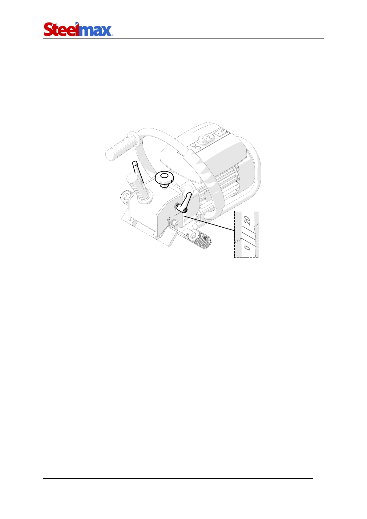
3.1. Adjusting the bevel angle and width
Unplug the machine from the power source. Start with setting the bevel width to zero.
To do this, loosen two lock levers (Fig. 2), rotate the knob to set ‘0’ on the bevel width
scale, and tighten the levers.
Fig. 2.Initial setting the bevel width to zero
To set the required bevel angle (Fig. 3), use the 6 mm hex wrench to loosen two side
screws. Rotate the guide set to get the required angle on the scale, and tighten the
screws in this new position.

BM-20 plus
BM-20 plus Operator’s Manual
10
Fig. 3.Setting the bevel angle (45° is set on the drawing)
After you set the bevel angle, use the depth knob to adjust the bevel width. The width
scale shows only a rough value because the bevel width varies with the angle.
The maximum bevel width (b = 21 mm, 13/16″) is for 45°. Find the required bevel
width for the required angle in practice. To do this, gradually increase the penetration
of the milling cutters into the workpiece.
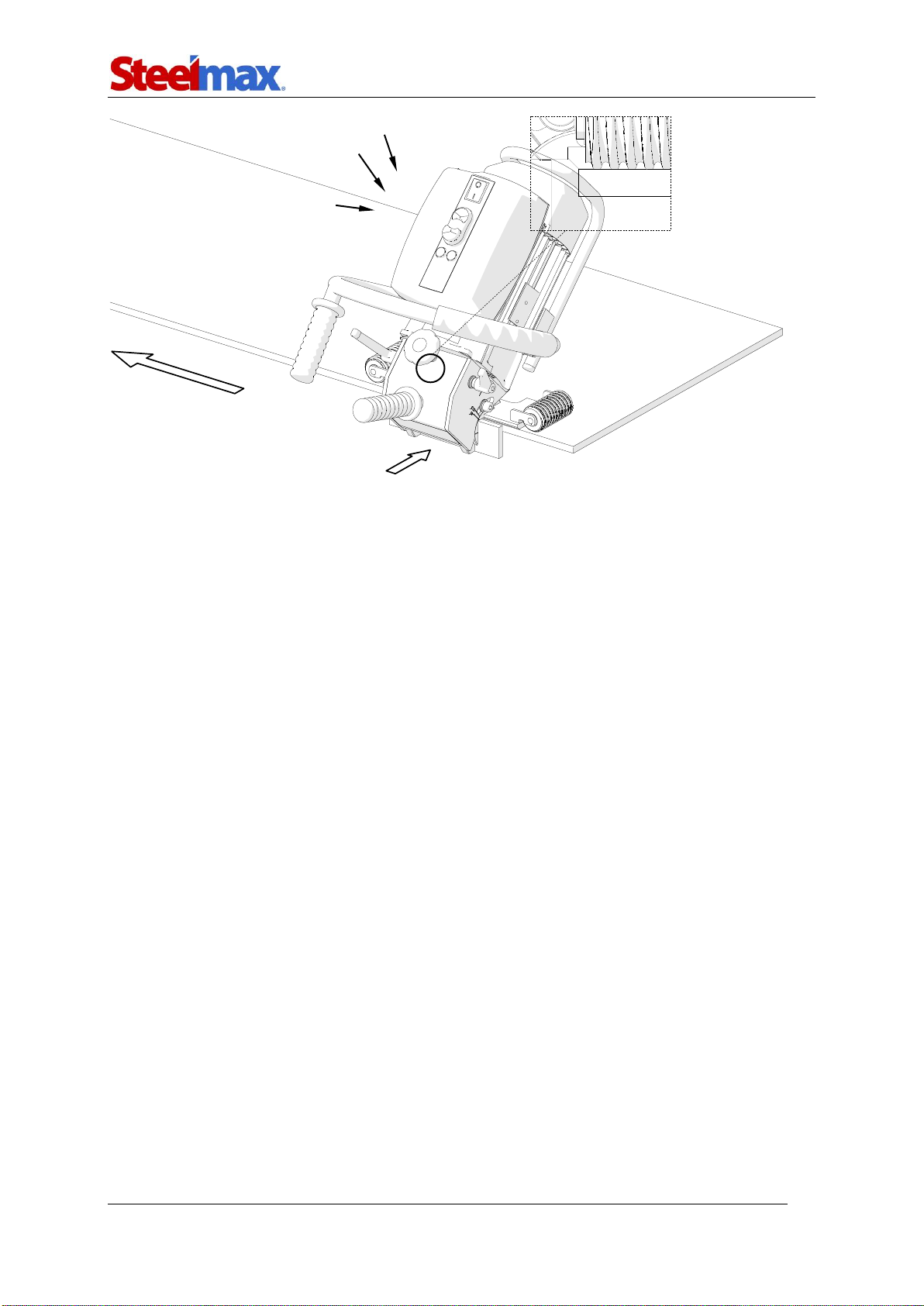
3.2. Operating
After you set the bevel angle and width, connect the machine to a correctly grounded
power source. Put the machine on the right so that the rollers are on the plate. Keep
a gap between the milling cutters and the plate (Fig. 4).
BM-20 plus
BM-20 plus Operator’s Manual
11
Fig. 4.Machine correctly put on the workpiece
Set the power switch to ‘I’ and press the green START button to start the motor.
Move the machine to the plate and bevel by moving the machine to the left.
Constantly press the machine to the plate.
Beveling is done according to the counter-rotation. The rotation direction of the
milling cutters is marked on the motor disk under the cover of the milling cutters.
The feed rate depends on the profile and composition of the workpiece.
Most steels capable of being welded can be beveled in one pass. However,
make bevels wider than 12 mm (1/2″) in at least two passes. This will require less
effort and time than if you bevel in a single pass.
To get the maximum bevel width (21 mm, 13/16″) in two passes, make the first
bevel width of about 14 mm (9/16″). For three passes, make the first bevel width of
about 12 mm (1/2″) and the second of about 16 mm (5/8″).
If an overload occurs because of, for example, too fast feed, the red overload
lamp comes on. If you continue work in such a case, the motor stops. Then, move
the machine away from the plate and set the power switch to ‘O’ to turn off the
power. Next, wait until the overload lamp comes off, and turn on the power again.
You can work near the overload (when the red lamp flashes), but do not let the
motor temperature increase more than 85°C (185°F). This can lead to damage of the
motor windings. After each hour of work under full load, stop the motor for 10–
15 minutes. Do not try to decrease the motor temperature by working without load.
The motor will then get hotter than when working with load.
Feed direction
Power switch
START
Slide toward after starting the motor
STO
P

BM-20 plus
BM-20 plus Operator’s Manual
12
After the work is finished, press the STOP button to stop the motor. Then, set the
power switch to ‘O’.
Clean the machine with a cotton cloth and no chemical agents.
3.3. Replacing the cutting inserts
Unplug the machine from the power source. Remove the levers (Fig. 5), and then
remove the cover of the milling cutters.

BM-20 plus
BM-20 plus Operator’s Manual
13
Fig. 5.Removing the cover of the milling cutters
Use the supplied T15P screwdriver to remove the fixing screw (Fig. 6), remove the
insert, and clean the socket. Rotate the insert by 90° and install again or replace to a
new one if all four edges are worn.
Fig. 6.Replacing the cutting inserts
When you make bevels of low width, the cutting inserts wear only on one, inner
corner. Then, the good thing is to change the inserts between the milling cutters
(Fig. 7). This will extend the life of the inserts.
Worn corners
Fixing screw

BM-20 plus
BM-20 plus Operator’s Manual
14
Fig. 7.Changing the cutting inserts between the milling cutters
3.4. Replacing the milling cutters
Unplug the machine from the power source and remove the cover of the milling
cutters as shown in Fig. 5. Use the 26 mm flat wrench to prevent the turn of the
spindle. Then, use the 8 mm hex wrench to remove the screw, and remove the
milling cutters (Fig. 8). To install, put the cutters on the key.
The 26 mm flat wrench and the 8 mm hex wrench are not included in standard
equipment.
Fig. 8.Replacing the milling cutters
Key

BM-20 plus
BM-20 plus Operator’s Manual
15
4. SPARE AND WEARING PARTS
Name
Number
Milling cutters set (2 cutters included, 10 inserts required)
KPL-0539-99-02-00-0
Cutting insert (sold 10 per box)
PLY-000282
Fixing screw for inserts
SRB-000311
T15P torx screwdriver for fixing screws
WKT-000005
Grease for screws (5 g, 0.17 oz)
SMR-000005

BM-20 plus
BM-20 plus Operator’s Manual
16
5. ACCESSORIES
5.1. 0° guide set for facing plates
Allows you to face plates.
To install the set, use the 6 mm hex wrench to remove two side screws (Fig. 9), and
remove the standard guide set. Then, install the 0° guide set in a way to get 45° on
the right scale, and tighten with the same screws.
Fig. 9.Removing the standard guide set and installing the 0° guide set
Part number:
ZSP-0075-32-
00-00-1
BM-20 plus
BM-20 plus Operator’s Manual
17
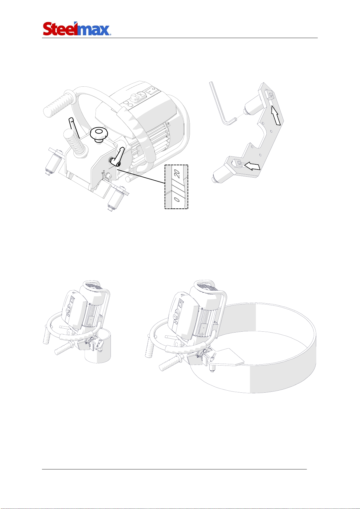
5.2. Guides for beveling pipes
Allow you to bevel pipes with outer diameters of 150–300 mm (6–12″) or 300–600
mm (12–24″).
To adapt the machine for work on pipes, use the 4 mm hex wrench to remove the
guide shown in Fig. 10. Then, in the same place attach the guide for pipes with the
four screws.
Fig. 10.Assembling the guide set for pipes
Part number:
ZSP-0075-31-00-00-0
(for pipes with diameters of 150–300
mm)
Pat number:
ZSP-0075-31-00-00-1
(for pipes with diameters of 300–600
mm)
BM-20 plus
BM-20 plus Operator’s Manual
18
Loosen the depth lock levers (Fig. 11) and rotate the depth knob to set ‘0’ on the
bevel width scale. Then, use the 6 mm hex wrench to loosen the rollers, and move
the rollers away from each other as far as possible.
Fig. 11.Initial setting the bevel width to zero and moving the rollers away
Put the machine on a vertical pipe so that the surfaces of the guide set are in contact
with the face and side of the pipe. Then, move the rollers symmetrically to make
them contact the pipe (Fig. 12) and tighten them in this position. Set the required
bevel angle and width as described before.
Fig. 12.Machine prepared for work on pipes with diameters of 150–300 mm and 300–600
mm
BM-20 plus
BM-20 plus Operator’s Manual
19
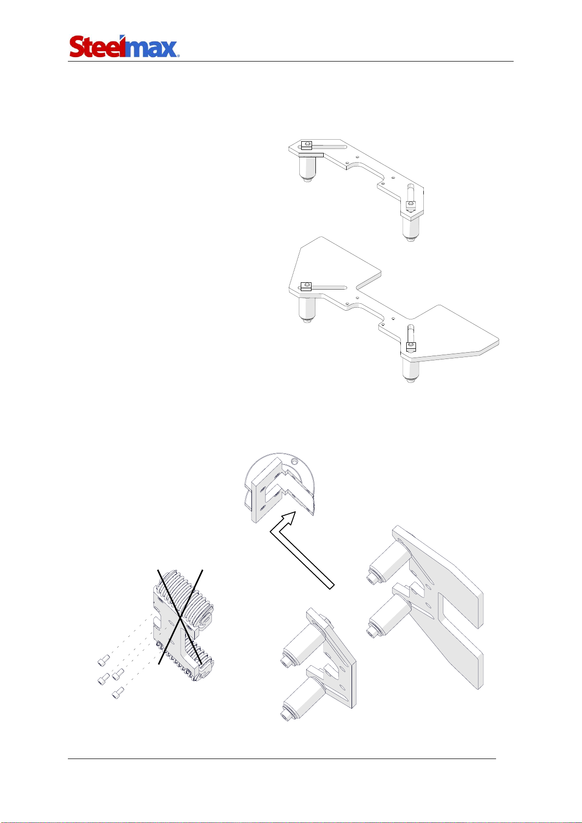
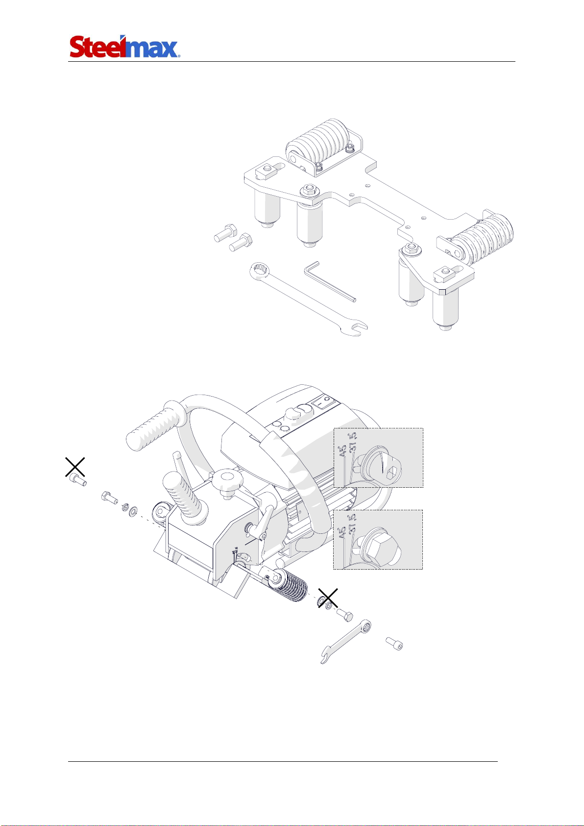
5.3. Guide for beveling round plates
Allows you to bevel plates that are rounded with a radius of at least 1000 mm (40″).
To adapt the machine for work on round plates, first on both sides replace the round
head screw with the hex head screw (Fig. 13).
Fig. 13.Replacing the screws of the guide set
Use the 4 mm hex wrench to remove both guides, and tighten the guide for beveling
round plates with four screws (Fig. 14). Next, use the 6 mm hex wrench to loosen the
outer rollers.
Part number:
ZSP-0539-10-
00-00-0
Befor
e
Afte
r

BM-20 plus
BM-20 plus Operator’s Manual
20
Fig. 14.Assembling the guide set for round plates; loosening the outer rollers
Put the machine on the plate (Fig. 15) so that the inner rollers are in contact with the
plate face. Then, move the outer rollers so that they come in contact with the plate
face and tighten them in this position.
Fig. 15.Machine prepared for work on round plates
5.4. Cutting tools
Part number
Part name
PLY-000591
Cutting insert (10 required, sold 10 per box)
Table of contents
Other SteelMax Power Tools manuals


