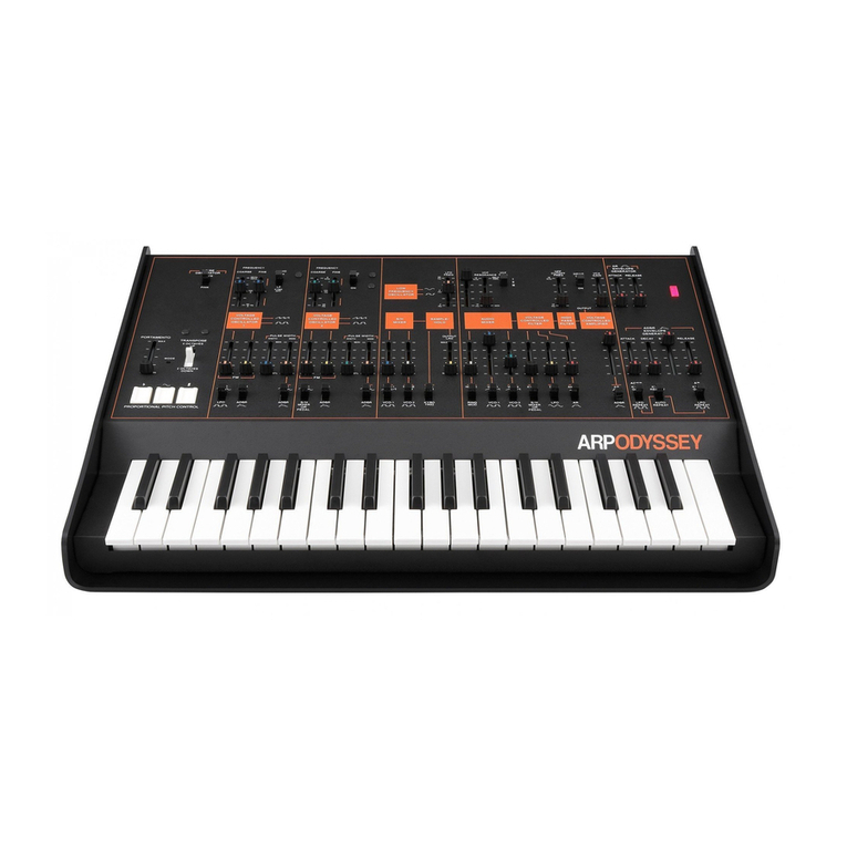
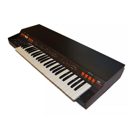
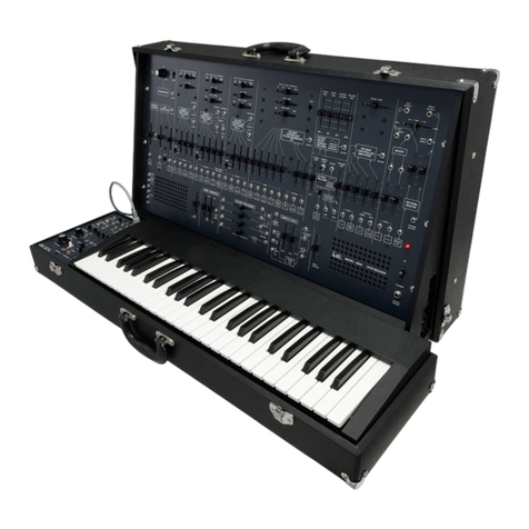
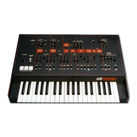
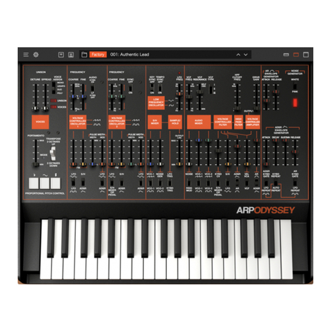
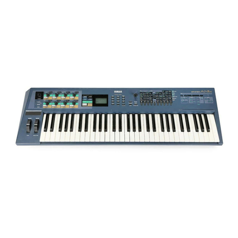
ARP ODYSSEY User manual

GLOSSARY
BASIC
BUILDING
BLOCKS Attenuator:
on
the
Odyssey,
a
Jr
D slider
that
lets sjgnal
through
.
when
it's
up
and
cuts
it
off
Oscillator (VCO}:
generates
tone.
when
it's
down.
Filter (VCF}: changes
tone
color.
Audio range:
the
range
of
pitches
Amplifier (VCA}:
controls
volume.
that
your
ear
can hear.
Envelope Generator (ADSR and Harmonics:
overtones.
The
more
AR):
controls
attack
and
decay.
harmonics
are
present,
the
ONIC
Frequency:
pitch.
Timbre:
tone
color.
Amplitude:
volume
Envelope:
attack
and
decay
shape.
ODYSSE'r
..
E.
MS
ADSR
and AR:·
attack,
decay,
sustain release.
Y:={)
aFand
rele&:
more
brilliance
the
sound
will
have.
Hertz(Hz): an
electronic
term
meaning
"cycles
per
second."
The
human
ear
can
hear
pitches
from
20
tG
20,000
cycles
per
second,
or
20Hertz
to
20
kiloHertz.
(20Hz
-
20KHz)
.
Highpass filter (HPF): changes
timbre
by
cut.ting
off
low
harmonics
and
passing high
ones.
Internal clock:
adjustable
low
frequency
oscillator.
Lowpass filter (VCF}: changes
timbre
by
cutting
off
high
harmonics
and
passing
low.
ones.
Mixer:
combines
signals.
Noise: a
random
signal
that
sounds
like a
"hiss."
Odyssey:
the
ultimate
musical
trip.
Phase:
the
relationship
of
one
waveform
to
another.
sine waves sine waves
in
phase.
out
of
phase.
---~
---·
~er
~'--"-'
Phase-synchronization: using
one
oscillator
to
control
the
phase
of
another
oscillator
of
different
pitch.
Pitch bend:
control
of
the
frequency
of
a
note
while
it's being
played.
Portamento: a glissando,
or
sliding
between
notes.
Resonance:"wow"
control.
In
electronic
terms,
a
control
that
amplifies a
narrow
band
of
·
overtones.
Sample & hold:
produces
a series
of
steps,
which
can
control
pitch,
volume,
or
brilliance.
Triggers itself
automatically.
17
2
Sub-audio range (Low frequency):
pitches
that
are below
what
your
ear
can
hear
as a
tone.
Trigger:
an
electronic
impulse
put
out
by a
keyboard
or
low
frequency
oscillator
that
starts
the
envelope
generator.
Voltage control:
on
a
synthesizer,
it
means
substituting
an electrical
signal
for
manual
control
of
pitch,
brilliance,
volume,
and
attack
&
decay.
Waveform:
tone.
Different
shapes
of
waveforms have
different
timbre
:
Square:
n._ru-u
sounds
hollow,
reedy.
Pulse: fL....n_fL_j
sounds
thin,
nasal.
Sawtooth:
~
sounds
rich, full, brassy
Sine:
~
sounds
smooth,
round,
pure.
Ring modulator:
produces
a single
complex
output
signal
which
contains
all
the
sums
and
differences
of
the
two
inputs.
Learn
to
take
yourself
on
the
ultimate
musical
trip!
...
"I
j
dys
Electronic
Music
Synthesizer
uid--

Your
ARP
synthesizer
is
warranted
for
the
original
purchaser
only
against
defects
in
materials
or
workmansh
ip
for
one
full
year
from
date
of
purchase.
In
case
of
defect,
repairs will
be
made
without
charge
when
the
synthesizer
is
shipped,
transportation
prepaid,
properly
packed,
to
the
nearest
ARP
authorized
servi
ce
center
.
These
warranties
do
nbt
cover
defects
resulting
from
accident,
alteration
,
improper
use,
unauthorized
repairs,
tampering,
or
failure
of
the
purchaser
to
follow
normal
operating
procedu
res
outlined
in
the
user's
manual,
nor,
for
example,
does
it
cover
dam
age
resulting
from
acts
of
Go
d,
such
as,
flood,
tornadoes,
or
lightning. Parts
replaced
under
these
wa
r
ranties
are
warran
ted
on
ly
through
the
remaining
portion
of
the
original
warranty.
This
warranty
becomes
effective
only
when
the
ARP
Warranty
Registration
card
is
properly
filled
out
with
all
the
required
information
and
received
at
ARP
INSTRUMEN
T
S,
INC.
within
14
days
from
the
date
of
purchase
.
The
foregoing
warranties
are
in lieu
of
all
other
warranties
express,
implied
, or
statuto
r
y,
including
but
not
limited
to
any
implied
warranty
or
merchantability
or
fitness,
and
all
other
obligations
or
liabilities
of
ARP
INSTRUMENTS,
INC.
In
no
event
shall
ARP
I
NSTRUMENTS,
INC. be liable
for
special
or
consequential
damages,
or
for
any
delay
in
the
performance
of
this
warranty
due
to
causes
beyond
its
control.
If
your
Odyssey
fails
during the first year after purchase, contact the dealer from
whom
it
was
purchased or the factory to obtain the name and address
of
the nearest A RP authorized service
center. Do
not
return
your
Odyssey to the factory
without
getting prior approval. You are
responsible for getting
your
Odyssey safely to the service center
and
back.
If
you
ship
your
Odyssey, be certain to insure
it
for its full value and enclose a
note
describing the problem.
And
pack
it
well.
IM
POR
TANT!
The enclosed Warranty card must
be
returned
to
the factory within
14
days
of
purchase.
r.'\
l2J
Table
of
contents
Setup
..................
3
Voltage control . . . . . . . . . . . . 4
Assembling a
sound.
. . . . . . . . . . 5
Signal sources . . . . . . . . . . . . . . 6
The "assembly l
ine"
.
.......
...
7
Phase
sy
nchronization . . . . . . . .
..
8
Ring modulation . . . . . . . . 9
Vo
ltage controlled filter . . . . . . . . 10
Highpass filter &
Ampl
ifier. . .
11
Envelope generators. . . . . . .12
Low
fre
quency osci
ll
ator.
.......
13
Sam
pl
e &
ho
l
d.
. . . .. . . . . . . . .
14,
15
Keyboard & pedals . . . . .16
It's a variable
synt
hesizer ! . . . . : . .17
~~
ODYSSEY
GUIDE
Instant Odyssey . . . . . . . . . .
18
2-Voice with Pedal . . . . . . . . 19
Phase-Synchronized Oscillator ..
..
..
20
Guitar-Lesl
ie
.
..............
21
Trumpet . . . . . 22
Trumpet Chorus . . . . . . . . . . . .
23
String Chorus . . . . . . . . ·. . . . . .
24
Flute. . . . . . . . . 25
Electric Bass, . . . . . . . . . . . . . . 26
· 'Hammond-Leslie'. . . . . . . . . . . . 27
Sa
mple & Hold Percussion .
28
Ba
n
jo
with Repeat
Gong/Chime. . . . . 29
. 30

ROCK STAR ENGINEER
CLASSICAL
~,/
PROFESSOR
FAN
JAZZMAN
Copyright ARP Instruments, Inc.
0
!Inn
320
Needham
Street
~
Newton, Mass.
02164
First Printing.
..
.November, 7972
SET UP
YOUR
ODYSSEY
1.
Remove
the
instrument
from
its
shipping
carton.
Do
not
throw
the
carton
a:nd
packing
materials
away.
They
can
be used
to
protect
the
Odyssey
in
transportation.
2.
The
Odyssey
should
be
placed
on
a
firm
support
about
30"
off
the
floor
so
that
its key-
board
is
at
a
comfortable
playing
height.
An
optional
performance
stand
is
available
from
your
dealer.
3.
Connect
the
power
cord
to
a
grounded
110-117 VAC
electrical
outlet.
The
power
switch
in
the
upper
right
corner
of
the
control
panel will
light
up
when
the
Odyssey
is
turned
on.
4.
Like all
electronic
musical
instruments,
the
Odyssey
must
be
connected
to
an
amplifier
and
loudspeaker
system
in
order
to
produce
sounds.
The
phone
jack
labeled
"low
level"
on
the
back
of
the
instrument
is
for
use
with
standard
musical
instrument
amplifiers.
The
smaller
phono
(RCA)
jack
next
to
it
is
la-
beled
"high
level"
and
should
be
used in
connecting
your
Odyssey
to
a
tape
recorder,
stereo
amplifier,
or
electronic
organ.
5. A
foot
switch
and
pedal
control
have
been
supplied
with
your
Odyssey.
Connect
these
to
the
rear
panel
jacks
labeled
"pedal"
and
"switch."
The
pedal
is
not
.a
simple
volume
control
such
as
you
are
familiar
with
if
you
have
played
electronic
organs;
it
is an integral
part
of
the Odyssey
and
is
essential for realis-
ing
the
full
potential
of
the instrument.
6.
You
are
now
ready
to
make
music
with
your
Odyssey.
You
can
begin
immediately,
if
you
wish, by
turning
to
the
end
of
this
man-
ual
and
setting
up
any
one
of
the
"patches"
given
there.
There
are
thousands
of
patches
you
can
discover
on
your
own,
and
in
the
next
few
pages
of
this
manual
we will
show
you,
in
simplified
form,
how
you
can
discover
some
of
them.
7. Until
you
are
quite
familiar
with
the
range
of
sounds
your
Odyssey
can
produce,
it
will
be
a
good
idea
to
keep
the
tone
controls
of
your
amplifier
set
to
their
"flat"
or
normal
position.
Later
on,
of
course,
you
can
use
them
freely,
together
with
reverberation
if
your
amplifier
provides
it.
Setup
ARP
ODYSSEY
Page
3

HOW
YOUR
ODYSSEY
WORKS
1.
Most
purely
electronic
musical
instruments
work
by
generating
certain
kinds
of
"raw"
sounds
from
circuits
called oscillators.
These
raw
sounds
(not
usually
very
pleasant
or
musi-
cal
sounding
by
themselves)
are
then
modified
by
other
circuits
such
as filters
to
make
them
musically
useful.
In a very general
way,
th
is is
how
your
Odyssey
works,
but
there
are
im-
portant differences.
2.
One
difference
is
that
the
synthesizer
gives
you
complete control
over
every
step
of
the
process
that
turns
a raw
sound
into
an
inter-
esting
musical
event
or
series
of
events.
All
of
the
slide
controls
on
the
upper
half
of
your
Odyssey
control
panel,
for
example,
re-
present
forms
of
sound
modification
that
either
do
not
exist
on
other
electronic
musical
instruments
or
are
buried
deep
inside
where
only
a
serviceman
could
reach
them.
3.
The
biggest
difference,
however,
is
that
with
your
ARP
Odyssey
the
process
of
whitt-
ling a raw
sound
into
something
musically
in-
teresting
can
be
controlled
not
only
manually
but
also, in several
important
respects,
auto-
matically.
This
is
the
principle
of
voltage
control,
which
means
controlling
the
operation
of
your
synthesizer
by
means
of
changing
volt-
ages as well as
changing
slider
positions.
Some
of
the
circuits
in
your
Odyssey
exist
only
in
order
to
produce
such
control
signals.
(Some
of
these
are
the
sample/hold
circuit,
the
two
envelope
generators,
the
L
FO,
and
the
key-
board.
)
4.
In a
modern
manufacturing
plant
many
operations
such
as drilling, milling,
and
lathe
work
will
be
controlled
by
computer.
Most
of
us have seen
at
one
time
or
another
a film
of
this
sort
of
thing-a
piece
of
raw
material
being
locked
into
place
and
machined
to
a
certain
size,
with
holes
of
a
certain
depth,
width,
and
placement-and
so
on.
You
can
think
of
your
Odyssey
as
being
such
an
"assembly
line"
for
the
construction
of
sounds.
Page
4
ARP
ODYSSEY
How
it
works: Voltage control
Audio
signals
from
the
two
voltage controlled
oscillators
(VCO
1
and
VCO
2),
the
noise
gen-
erator,
and
ring modu-
lator
are
mixed
and
passed
th
rough
the
volt-
age
controlled filter,
the
high
pass
filter,
and
the
voltage controlled amp-
lifier
before
leaving
the
synthesizer.
The
output
of
the
voltage control-
ed
amplifier
is
connect-
ed
to
the
output
jacks
on
the
back
of
your
Odyssey.
5.
The
ARP
Odyssey
contains
about
a
dozen
separate
pieces
of
equipment
(plus
a
few
extra
controls
such
as
the
portamento
and
pitch
bend
controls
on
the
far
left
of
the
panel.)
These
can
be
connected
to
each
other
in
many
different
ways
by
the
switches
and
sliders
to
produce
thousands
of
different
"assembly
pro-
grams"
or
patches.
Each
patch
requires:
a.
at
least
one
piece
of
equipment
to
gen-
erate
the
raw
material
from
which
the
sound
is
to
be
made;
i.e., a
signal
source.
b.
at
least
one
piece
of
equipment
to
modi-
fy
the
raw
material
and
make
it
usable;
i.e.,
a
signal
modifier.
c.
one
or
more
pieces
of
equipment
for
control
Iing
the
signal .sources
and
signal
AUDIO
MIXER
VOLTAGE
1--~CONTROLLED•--~
FILTER
Keyboard
Control
from from
Noise Gen
Voltage
S/H
or
Envelope
VCO
1
VCO
2
or
Ring
Mod
or
Pedal
LFO
Generators
AUDIO
SIGNALS CONTROL SIGNALS
modifiers;
i.e.,
control
signal
sources,
some-
times
simply
called controllers.
6.
The
front
panel
of
your
Odyssey
shows
the
general
assembly-line
setup
(Figure
A).
Thus,
to
reach
your
amplifier
and
loudspeaker
system,
a signal
must
pass
through
this"assembly
line."
This is the heart
of
your
Odyssey. By using
the
sliders
and
switches
of
the
audio
mixer,
you
can
select
the
raw
material
for
processing
by
the
voltage
controlled
filter
(VCF),
the
high pass
filter
(HPF),
and
the
voltage
con-
trolled
amplifier
(VCA). In
the
next
few
pages,
we will
show
you
exactly
what
each
part
of
the
assembly
line
does
by
itself;
the
sample
patches
at
the
end
of
the
manual
show
some
of
the
ways
they
all
work
together.
HIGH
PASS
FILTER
VOLTAGE
•--~
CONTROLLED
AMPLIFIER
Envelope
Generators
AUDIO
OUTPUT
Figure A
Assembling a
sound
ARP
ODYSSEY
Page
5

INDIVIDUAL
FUNCTIONS
IN
THE
ODYSSEY
1.
Set
all
the
controls
on
your
Odyssey
as
in
Figure B.
There
should
be
no
sound
coming
from
your
speakers
when
the
controls
are
set
Figure
C
8
like
this,
even
if
you
press
a
key.
But
the
assembly
line
is
"wide
open"
and
will pass
any
signal
from
the
audio
mixer
in
unchanged
form.
2.
Opening
the
first
slider
under
the
audio
mixer
will give
you
a
steam
-like
hissing
noise
from
the
noise
generator.
The
noise
generator
is
a signal
source,
and
has
one
control,
located
in
the
upper
left
corner
of
the
panel
(Figure
C).
Moving
this
switch
down
will give
you
the
lower-pitched
sound,
like a
distant
waterfall,
of
pink
noise.
These
raw
sounds,
suitably
modified,
are useful in
the
production
of
wind,
thunder,
surf,
and
motor
or
machine
effects.
See
Patch
10,
for
some
of
these.
Close
the
first
slider.
3.
Open
the
second
slider
and
you
will
hear
a
rich
buzzy
tone
from
voltage controlled oscil-
lator 1 {VCO 1).
The
pitch
of
this
tone
can
be
changed
manually
by
the
coarse
and
fine
tuning
sliders
(Figure
D),
and
by
voltage
con-
trol
from
the
keyboard
(try
playing
the
key-
Page
6 ARP
ODYSSEY
Signal sources
board
using
al
I
three
p·ositions
of
the
transpose
switch
at
the
left
of
the
control
panel).
Other
control
signals
can
affect
the
frequency
of
VCO
1
through
the
two
sliding
attenuators
shown
in
Figure
E.
Experiment
with
the
in
-
dicated
controls.
An attenuator
acts
like a
valve,
or
faucet,
to
set
the
amount
of
a
control
signal
that
passes
through
it
to
affect
a
voltage
controlled
device.
An
attenuator is closed
when
it
is all the way down, and open when
it
is
all the way up,
VCO
1
produces
two
kinds
of
output
signals;
you
have
been
listening
to
the
sawtooth signal
(so
called
because
it
is
a
pattern
of
voltage
changes
which
look,
on
a
graph,
like
the
teeth
of
a
saw).
It
is
the frequency with which this
pattern is repeated every second
that
deter-
mines what pitch
you
hear.
You
can
hear
the
puJse
signal
by
moving
the
middle
switch
under
the
audio
mi
xer
down
(
Figure
F.
).
Figure
D
AUDIO
l~f·I ~
ICYBO
2!211
OFF
'
';"
,,
~
L
FO
S/H
IV\,
ij
~J.
JUl
.I'----.
Figure
E
Figure F
LFO
N'v
B
ADSR
"'-
VCO· l
N---1-
ii
I
MAX
-
"'"
Figure
B
TRANSPOSE
2 OCTAVES
UP
2 OCTAVES
DOWN
VOLTAGE
CONTROL
L
ED
VOL
TAGE
CONTROLLED
OSCILLATOR
J"'Ln
OSCILLATOR .f1.J'l..
l~~vC7
HPF
GENERATOR
:f
tr
I
JII
CONTROLLED
1 2
11
II
II
II
tt-1ttIIl1* lIIII
~
FM
~
J_
~
FM
-=_j
J_
J_ J_ J_
J_
J_
J_
J_
J_
J_
J_
ADSA
LFO
LFO S/H
N'v
IV\.
~ ~
!'-
LFO
VCQ.1 NOISE LFO NOISE VC0·1
1/00·2
KYBD
S1H
ADSR AR
r-::D
I(~
rl(~:a
7
~jjij
;~~,
:
~~
ftf,~
REPEAT
JUl
The "assembly
line"
ARP
ODYSSEY
Page
7

Figure G
ll
J_
LFO
IV\,
B
ADSR
,._
Experiment
with
the
pulse
wi_dth
control
on
VCO
1
and
then
with
the
pulse
width modu-
lation signal
attenuator
(Figure
G ).
Moving
the
switch
shown
in
Figure
H
down
lowers
the
frequency
of
VCO
1
by
a
factor
of
about
a
hundred.
This
is
far
below
the range
of
human hearing;
consequently
you
will
not
hear
any
continuous
tone
but
only
a
more
or
less
rapid
series
of
-clicks
(depending
on
the
coarse
and
fine
frequency
settings).
In
this
low frequency
range
VCO
1
is
not
control
led
by
the
keyboard
{if
it
were,
the
click-frequency
would
double
with
every
keyboard
octave),
and
can
be used as a
source
of
control
signals.
4.
Return
the
controls
on
the
Odyssey
to
the
positions
shown
in Figure
B.
Now
open
the
third
slider
under
the
audio
mixer
to
hear
the
raw
sawtooth
signal
from
voltage controlled
Page
8 ARP
ODYSSEY
Phase synchronization
oscillator 2
(VCO
2).
VCO
2
is
exactly
like
VCO
1
except
for
two
things:
a.
VCO
2
does
not
have a
low-frequency
operating
range.
b.
VCO
2
can
be synchronized
to
VCO
1.
Phase
synchronization
of
the
two
oscillators
is
accomplished
by
the
switch
at
the
top
right
in
Figure
I ,
labeled
c'sync
off/on."
When
this
switch
is
on,
the
audio
signal
from
VCO
2 is
forced
to
conform
to
the
frequency
of
VCO
1.
You
can
hear
this
effect
in its raw
form
by
set-
ting
\/CO
1
to
some
relatively
low
audio
fre-
quency
(near
the
"100
Hz"
mark}
and
slowly
moving
the
coarse
tuning
control
of
VCO
2
through
its
entire
range
from
bottom
to
top.
Experiment
also
with
changing
the
frequency
of
VCO
1
while
leaving
VCO
2 in
about
the
middle
of
its range.
Patches
2,
3,
and
others·
make
use
of
this
spectacular
sound.
At
this
point,
too,
with
the
sync
switch
off,
you
should
practice
tuning
VCO
1
and
VCO
2
to
various
musical
intervals
by
opening
both
the
second
and
third
sliders
under
the
audio
mixer.
AUDIO
COARSE
FINE
ICYBD
:
:~
I 9
-
-~M•
-
- -
~-·
l
I
VOLTAGE
COHTROLLED
OSCILLATOR .J'\..fl.
1
Figure
H
Figure
I
*Be
sure
you
have
returned
the
sync
switch
to
"off"
when
you
first
try
the
ring
modulator.
Figure J
5.
Beginning
from
the
position
of
Figure
B,*
open
the
first
slider
under
the
audio
mixer
again
and
listen·
to
the
ring modulator.
The
ring
modulator
is
a signal
modifier,
and
when
you
are
listening
to
it
you
should
think
of
your
assembly
line as
it
is
shown
in
Figure
J.
The
ring
modulator
has
no
controls
of
its
own.
It
produces,
from
the
pulse
outputs
of
VCO
1
and
VCO
2,
a single
complex
output
signal
which
contains
all
the
sums
and
differences
of
the
two
oscillator
frequencies.
This
means
that:
a.
the
raw
sound
produced
from
the
ring
modulator
depends
entirely
on
the
tuning
of
VCO
1
and
VCO
2;
and
to
a lesser
extent
on
the
pulse
width
settings
for
each
one.
Experiment
with
these.
Note in particular
vco 2
that
sounds from the ring mo(fulator do
not
necessarily have any standard musical pitch
in relation to the pitch
of
either oscillator.
(Unless
they
are
synchronized
by
the
"sync"
switch
on
VCO
2;
try
that-)
b.
the
overtones
of
the
ring
modulator
sig-
nal will
not
necessarily
conform
to
the
stan-
dard
harmonic
series.
They
may
be
extreme-
ly
complex,
like
those
of
a bell,
chimes,
gongs,
and
other
metallic
or
percussive
sounds.
All
of
these,
in
fact,
can
be
simu-
lated
by
further
modifications
of
a
suitable
ring
modulator
signal; see
Patch
12.
OUTPUT
RING
VOLTAGE
MODULATORi----CONTROLLED
FILTER
HIGH
PASS
FILTER
VOLTAGE
CONTROLLED
AMPLIFIER
vco 1
Ring
modulator
ARP
ODYSSEY
Page
9

6.
The
voltage controlled filter
(VCF)
is
a
signal
modifier.
It
alters
the
sound
of
signals
passing
through
it
by
selectively
removing
or
weakening
their
higher
frequencies.
Listening
to
pink
noise,
with
the
settings
as in
Figure
K,
move
the
VCF
freq
slider
slowly
down
as
far
as
it
will go.
You
will
hear
first
the
highest
frequency
components
of
the
noise
weaken
and
disappear,
then
middle
frequencies,
and
finally
even
the
lowest
bass
disappear
until
no
signal
is
audible
at
all.
Try
the
same
procedure
with
signals
from
one
or
both
of
the
VCO's
instead
of
pink
noise.
Raise
the
resonance
slider
about
halfway
up,
as in Figure
L,
and
repeat
the
experiment,
first
with
pink
noise
and
then
with
an
oscillator
signal. With
this
resonance
setting,
the
VCF
"peaks"
sharply
around
a
narrow
range
of
frequencies;
this
is
useful in
creating
various
"wa-wa"
effects.
The
highest
position
of
the
resonance
slider
is
labeled
"self
osc"
(Figure
M
).
In
this
position
the
VCF
is
an
oscillator
just
like
one
of
the
VCO's
and
will
produce
an
output
even
with
all
th
e
input
sliders
on
the
audio
mixer
closed.
In
other words,
it
becomes a signal source
rather than a signal modifier.
i
V
CF
,
.••
1
~~"
..
"
1
~ri~F
Ii~
1
,~'fu
.:
..
1
°"v
c~"
..
c
1
~rir
I
ii,~
«:'.Hr
OSC
KHl
IC
Hr
0SC
II.HZ
-- --
--
--
--
--
--
--
--
--
--
--
--
--
--
--
--
-- --
--
--
1111
16
UI
18
H,
M!M
Hz
- - -
ltz
MIN
Hr
- -
OUTPUT
OUTPUT
AUDIO
MIXER
II I
~1~1-
II
-
---- -
--- -
--- -
J_ J_ J_ J_
J_
i!
assaa AR
e
RING
vco.1
VC0•2
sri.
LFO
AR
MOO J"'V1.. .I'\.J"L
MIXER
1\/v
J'-..
_r--..._
OR
PEDAL
Figure K
AUDIO
MIXER
VOLTAGE
CONTROLLED
VOLTAGE
CONTROLLED
II
'fl
I
J_
J_
J_
J_
J_
J_
VCO·l S/H
AR
r---.r--.1"
~
CV
./'--....
.f7...
Ii
BB
8
BB
B
RING VCO·l VC0·2 S/H
AA
MOO
_nn_
_nn_
~f~{:
Nv
~
~
I
VCF
RE~;,.CE
]~
Figure
M
Page
10 ARP
ODYSSEY
Voltage controlled filter
AUDIO
MIXER Figure L
The
VCF
resonance
can
only
be
set
manually.
The
VCF
frequency can
be
set
and
changed
with
control
voltages
as well as
by
hand;
using
noise as
your
input
signal,
open
the
first
con-
trol
input
attenuator
all
the
way
(Figure
N)
and
set
the
manual
VCF
freq slider
about
half-
way
up.
Now
run
long
glissandos
on
the
key-
board
and
listen
to
the
noise
grow
alternately
brighter
and
duller.
Close
this
attenuator
and
open
the
next
one
to
introduce
control
by
the
LFO
sine
output.
(By
this
time,
you
should
develop
the
habit
of
experimenting
with
all
the
relevant
controls
for
any
functions
in use;
in
this
case,
for
example,
you
will
want
to
hear
different
settings
of
the
L
FO
frequency
and
the
VCF
resonance
and
manual
VCF
frequency
settings.)
Often
you
will
want
to
control
the
VCF
frequency
by
the
ADSR
or
AR
envelope
gen-
erators in
order
to
create
separate
events
with
their
own
attack
and
decay
characteristics.
For
an
example
of
this,
feed
one
of
the
VCO
~
signals
into
the
audio
mixer
and
move
the
VCF
freq
slider
all
the
way
down.
Open
the
third
con'trol
attenuator
under
the
VCF
all
the
way
(all
the
other
controls
on
your
Odyssey
~hould
+rhus
the
HPF
is
"wide
open"
when
the
HPF
Cutoff
Freq
control
is
all
the
way
down.
HPF
I
FREO
"··~:":"
"CI~~~~f
KMr
0SC
KHI
-- - -
-- - -
- - - - -
,,
10
-Hr - - MIN
Hz
AUDIO
MIXER
II
ll1
J_ J_
J_
l_ l_ l_
Beeeee
RING
VC0-1 VC0-2
Sl'H
LFO
A.R
MOO
JUL
IlJ"L
:E~~::
AJv
F>._
~
control
inr:>ut
attanuators
Figure
N
be
set
as in
Figure
B),
and
play
the
keyboard.
Contrnue
with
various
settings
of
the
VCF
freq,
the
third
attenuator,
and
the
four
con-
trols
of
the
ADSR
envelope
generator.
In
general,
the
higher
the
setting
of
the
third
attenuator,
the
lower
you
will
want
to
set
the
VCF
freq,
and
vice versa.
7.
The
high
pass
filter
(HPF)
is
another
signal
modifier.
It
attenuates
frequencies
below
the
setting
of
its
HPF
cutoff
frequency
slider
and
thus
is
exactly
opposite
in its
effects
to
the
VCF
which
is
a
low
pass
filter.*
It
is useful in
eliminating
"boominess"
from
low
bass
notes,
and
in
simulating
certain
instrumental
sounds
(see
Patch
6).
The HPF is
not
voltage con-
trolled.
8.
The
voltage controlled amplifier
(VCA)
is
the
final signal
modifier
stage
of
your
Odyssey
"assembly
line."
It governs the volume
of
the
synthesizer's output.
The
most
common
way
of
using
the
VCA
is
to
set
its
VCA
gain
slider
all
the
way
down
and
the
control
attenuator
all
the
way
open.
(See
Figur
e O
on
page
12.)
Thus
the
VCA
will
allow
signals
to
pass
through
only
when
it
is
"instructed"
to
do
so
by
one
of
the
envelope
generators.
Highpass filter &
Amplifier
ARP
ODYSSEY
Page
11

9.
The
two
envelope generators
are
controllers.
They
are
most
often
used
to
program
the
attack
and
decay
of
events
by
controlling
the
gain
of
the
VCA
or
the
frequency
of
the
VCF.
The
upper
envelope
generator
in
Figure
O
has
two
control
sliders,
one
for
attack time,
and
one
for
release
time.
It
is
referred
to
as
the
AR
generator.
The
lower
generator
has
con-
trols
for
attack time, decay time,
sustain
level,
and
release
time,
and
is
thus
abbreviated
as
the
ADSR
generator.
With
your
Odyssey
controls
set
as in
Figure
B,
feed
pink
noise
into
the
audio
mixer
and
close
the
VCA
gain
slider
all
the
way
down.
Open
the
control
attenuator
under
the
VCA
all
the
way
as in
Figure
P,
and
depress
any
key
on
the
keyboard.
Raise
the
attack
slider
on
the
AR
generator
a
little
way
and
depress
a
key
again.
Continue
to
do
this,
each
time
raising
the
attack
control
a
little
more
until
it
is
all
the
way
up.
Then
move
it
down
again
and
repeat
the
whole
procedure
using
the
release
slider.
Now
experiment
with
VCA
control
by
the
ADSR
generator;
move
the
selector
switch
un-
der
the
VCA
control
attenuator
down
as in
Page
12
ARP
ODYSSEY
Envelope generators
Figure
P
and
try
various
settings
of
the
four
ADSR
controls.
By
closing
the
VCF
freq
slider
and
opening
the
third
attenuator
under
the
VCF
all
the
way
as
in
Figure
Q,
you
can
give
yourself
a
similar
introduction
to
ADSR
and
AR
control
of
the
VCF.
Experiment
too
with
various
combina-
tions
of
the
VCF
freq
and
control
attenuator
settings,
and
with
various
mixes
{by
means
of
the
input
attenuators
to
the
audio
mixer)
of
J:~;:~~"LED
signals
from
VCO
1
and
VCO
2.
·l::'.:
r--;,;v:~:E
~T;;;--,
Up
to
now
you
have been triggering the enve- 4a
•1c•
OE
.
CAY
SUSTA
.
IN
RELEASE
lope generators
only
from the keyboard. By _
-1-1
-1
means
of
the
three
switches
at
the
bottom
right
of
Figure
R,
you
can
also
trigger
the
er'lve.lope
generators
with
the
LFO.
Move all
three
switches
down
and
set
the
other
controls
of
J_
your
Odyssey
for
AR
or
ADSR
control
of
the
.,
~/
08
".:;-i J l 1
.~:07
VCF
or
VCA as in
Figure
R;
now
try
different
8 !
"g
9
settings
of
the
LFO
freq
slider
from
low
to
AOSR
lfli
.
•uro
REPEAT
.r-.._
REPEAT
REPEAT
JU1
high. With
the
first
switch
down
and
the
sec- ..,_
___
.n.n._
_____
.....
_
_.
ond
switch
up,
a series
of
events
will be
pro-
duced
(triggered)
by
the
LFO,
but
only
when
a
key
is
depressed.
This
is
useful
in
simulating
--
-banjo-picking
and
strumming
as in
Patch
11.
Return
switches
under
ADSR
and
AR
to
upper
position.
Figure
P
VOLTAGE
CONTROLLED
ll
l_ l_ l_
ICYBO
5m
ADSR
CV
.I'--,__
8 B
l!!I
S/H
LF
O
AR
MIXER
fV'v
r-\_
PtD~L
Figure
Q Figure R
Figure
S
10.
The
low frequency oscillator
(LFO)
is
a
controller;
its
output
signal is never used
as
raw material
but
only
to
control other
functions within the Odyssey.
You
have al-
ready
heard
it
control
VCO
1 in
Figure
E ;
now,
by
following
the
settings
of
Figure
S,
listen
alternately
to
LFO
square
wave
control
of
VCO
1
and
LFO
sine
wave
control.
In
one
case
you
hear
a
vibrato,
in
the
other
a trill.
Experiment
with
various
settings
of
the
LFO
freq
slider
and
of
the
control
attenuator
under
VCO
1.
The
L
FO
can
also be used
to
govern
the
oper-
ation
of
the
sample/hold
circuit
and
the
envelope
generators
which
you
will
read
about
later.
11.
The
sample
and
hold mixer (S/H mixer)
selects
and
combines
signals
to
be
fed
to
the
sample
and
hold
circuit.
These
signals
can
also
be
routed
to
control
VCO
2
and
the
VCF.
Under
each
of
these
two
functions
is
a
switch
labeled"S/H
mixer
or
pedal.,,
When
the
foot
pedal
is plugged
into
the
Odyssey,
the
lower
position
of
these
switches
selects
control
by
the
pedal;
if
the
foot
pedal
is
disconnected
Low
frequency oscillator
ARP
ODYSSEY
Pag_e
13

from
the
back
of
the
Odyssey,
the
same
switch
position
selects
control
by
the
output
of
the
5/H
mixer.
12.
The
sample
and
hold circuit js a
control-
ler; it
is
used
only
to
control
VCO
1,
VCO
2,
and/or
the
VCF.
In
order
to
hear
what
it
does
listen
first
to
VCO
2 as
you
have
done
before
and
then
experiment
with
the
controls
indi-
cated
in
Figure
T.
By
"sampling"
at
a given
instant
the
signal
voltage
from
the
S/H
mixer,
the
sample
and
hold
circuit
produces
a series
of
voltage levels.
If
these
in
turn
are used
to
control
a
VCO,
the
result
is
a series
of
pitches.
The
switch
under
the
sample
and
hold
circuit
selects
either
the
LFO
or
the
keyboard
as a
triggering
source.
If
the
keyboard
is
selected
(
Figure
U ),
then
a
new
sample
will be
taken
every
time
you
press
a key; if
the
L
FO
is
selected,
then
new
samples
will be
taken
at
regular
intervals
corresponding
to
the
frequency
setting
of
the
L
FO.
When
the
signal
sampled
is
primarily
noise,
the
output
voltage
levels will be
random
and
so
of
course
will be
the
pitches
produced
from
VCO
2 ;
but
if
the
signals
being
sampled
are
Page
14
ARP
ODYSSEY
Sample &
hold
Figure
T
AUDIO
~••~'-'-"!FINE
ii
'°"' t Cl
j r•uLSE
wroTH
7 I
ouTPur
J_ J_
:(
::
~t
:~
1-
~
-I~.
i
~
i
i --
i-
...
~
...
~
J_
J_
J_
Figure
U
LFO S/H LFO
VC0·1
NOISE
LFO
IV\,
fVv
"""
GEN
TRIG
f;1
a.
J;l
B
I!
I!
vro
-1
ftY
BO
_J1.J"\
~
.I"-...
.fUL .fUL
TAIG
AUDIO
ICYBD
SYNC
l:,;;t·I @
1-?·
·t e
zgg
OFF
100
'
"'
. --
,;
..
I _
-::
I
VOLT~GE
CONTROLLED
OSCILLATOR
.IV'\
1
1 l r
Pulse
w10TH 7 f f r
PULSE
w1
0TH
7
111111r-~
L..:::.
...
..=-i l_ t..=.,
..
_:__j
J_
LFO
LFO
S/H LFO
VCQ-.1
NOISE LFO
fVv
/\/\.
I\/\,
r-...J--.1-
GEN
TRIG
B
I!
B 8
LFO
FREQ
..
_I
·1
OUTPU
T
...
I:~
""ILAG
- - - -
--,
MIH l,IIH
l_ l_
LFO
TRIG
e
J;1
~r
~
AOSR VC0-1 VC0-2 t-'l'BO •
.r-,._
Ml~:R
_t--,.._
..J'-.....
J"U'1...
.J'l.I'L
TRIG
PEDAL
Figure V
See
Patch
10
for
a
thorough
sample
and
hold
patch.
Figure
W
regular
and
periodic
(any
combination
of
the
VCO
1
and
VCO
2 signals),
then
the
output
from
the
sample
and
hold
circuit
will
tend
to
be a
repeating
pattern
also. It
may
·be an ex"
tremely
complex
one,
or
it
may
be
extremely
simple
.
For
an
example
of
a
simple
one,
switch
VCO
1
to
its
low
freq
range
and
feed
the
VCO
1
sawtooth
into
the
S/H
mixer.
Use
the
sample and hold output
to
control
VCO
2
and
listen
to
VCO
2
through
the
audio
mixer.
Set
the
LFO
freq
to
about
halfway
up,
and
the
VCO
1
freq
at
about
2 Hz. You should
hear a descen.ding "staircase"
of
pitches, like a
scale passage or an arpeggio (Figure V ).
Speed
up
VCO
1
freq
and
hear
the
repeating
patterns.
The
output
lag
slider
(Figure
W )
"smootbes
out"
sudde.n
changes
of
voltage
from
the
sample
and
hold
circuit.
With
the
same
patch
you
have
been
listening
to,
move
the
slider
slowly
from
"min"
to
"max"
and
back
again.
13.
The.
keyboard
is
a
controller.
By
con-
trolling
the
pitch
of
the
VCO's
and
providing
triggering
signals
to
the
envelope
generators,
it
allows
you
to
play
your
Odyssey
as
though
it
were
a
standard
keyboard
instrument.
The
More sample &
hold
ARP
ODYSSEY
Page
15

transpose,
portamento,
and
pitchbend
controls
(Figure
X)
give
extra
flexibility
to
your
pitch
control
of
the
oscillators.
Set
the
controls,
to
start
with,
as
in
the
illus-
tration,
and
feed VCO 1
(either
the
sawtooth
or
pulse signal)
into
the
audio
mixer
with
the
VCF,
HPF,
and
VCA
wide
open.
Depress a
key
and
rotate
the
pitch
bend
knob
to
the
right,
then
to
the
left,
then
return
it
to
center.
Release
the
key
and
rotate
the
knob
again.
Note
that
it
operates
only
when
a
key
is
de-
pressed.
Return
the
knob
to
center.
Raise
the
portamento
slider
about
halfway
and
play a
short
melody;
note
the
"glide"
be-
tween
pitches.
The
position
of
the
portamento
slider
determines
the
speed
of
the
glide;
exper-
iment
with
different
settings.
The
transpose
switch
shifts
the
entire
keyboard
control
up
or
down
by
two
octaves.
Play a
scale up
the
keyboard
with
this
switch
cen-
tered,
and
then
with
the
switch
up,
then
with
the
switch
down.
In
this
way
the
keyboard
can have an
effective
range
of
seven
octaves,
almost
as wide as a
piano.
Page
16 ARP ODYSSEY Keyboard & pedals
The
foot switch
supplied
with
your
Odyssey
is
used
to
turn
on
the
portamento.
Thus
you
can
set
the
portamento
slider
for
a
certain
glide
speed
and
then
turn
it
on
and
off
with
the
foot
switch.
When
the
foot
pedal
is
plugged
into
the
back
of
your
Odyssey,
VCO
2
and
the
VCF
can be
controlled
by
it. (The signal
from
the
5/H
mixer
is
automatically
disconnected
by
insert-
ing
the
foot
pedal jack.) See
Patch
1
and
2
for
examples
of
its use.
Your
Odyssey
keyboard has two-voice capa-
bility.
Feed
both
oscillator
signals
into
the
audio
mixer
and
tune
them
to
unison
while
holding
down
the
lowest
key.
Now
VCO 1
will
follow,
or
"track,"
the
lowest
key
of
any
two
notes
you
play,
and
VCO 2 wil I
track
the
highest
key.
Thus
you
can
play
two
indepen-
dent
pitches
at
the
same
time.
For
examples
of
this
turn
to
page
20
and
begin
with
the
first
patch.
(When
you
are
setting
up a two-voiced
patch,
make
sure
the
"sync,,
switch
is
in
the
"off
11
position.)
PORTAMENTO
r
-
.,.
~
FLAT.Sl<ARP
PITCH
BEND
Figure
TRANSPOSE
2 OCTAVES
UP
8
2 OCTAi/ES
DOWN
X
!
I
HINTS
FOR
GETTING
THE
MOST
OUT
OF
YOUR
ODYSSEY
1.
You
may
tend
at
first
to
think
of
the
con-
trol sliders on
the
Odyssey
as
something
like
stop
tabs
on an
electronic
organ.
That
is,
you
may
be
tempted
to
set
them
in
a
certain
way
and
then
"play"
the
Odyssey
only
from
the
keyboard.
Try
to
overcome
this
temptation.
Use
the sliders in performance. Learn
to
change
the
sounds
you
are
producing
while
you
are
producing
them.
2.
The
patches
given
in
this
manual
are very
basic.
Do
not
hesitate
to
search
for
improve-
ments
and
variations
on
your
own.
In
many
cases a
slight
change
in
the
position
of
a single
control
slider
or
attenuator
can
make
a large
difference
in
the
sounds
you
are
producing.
3. Resist the temptation to merely open
as
many
sliders
as
possible,
as
far
as
possible.
It's a variable synthesizer: vary
it!
ARP ODYSSEY
Page
17

If
you
just
have
to
start
here:
INSTANT
ODYSSEY
Set up the sound shown on page 19 (opposite).
Play a two-part piece on the keyboard.
If
you hear two voices with pedal control, turn the page and trv more sounds.
If
what
you hear
is
nothing like two voices with pedal
control,
or
if
you don't hear anything,
check the following things;
1
).
Is
the "sync
off/on"
switch turned
off?
(
top
of
Oscillator 2).
If it's on, you'll hear only one voice even though you press down
two
keys.
2).
Is
the "audio
kbd
on/LF
kbd
off"
switch turned on? (top
of
Oscillator 1).
If it's off,
your
first tone source (VCO 1) will be way below
what
your
ear can hear.
3).
Is
the "HPF
cutoff"
slider all the way down? (top
of
High
Pass
Filter).
If it's up, you are
cutting
off
your sound by eliminating
all
but
the very highest overtones.
4).
Is
the "VCA gain" slider down? (top
of
Voltage Controlled Amplifier).
If it's up, you'll hear sound
all
the time, even when you take
your
hand
off
the keyboard.
5). Are the "attack, decay, sustain, release" sliders raised partway? (under
ADSR
Envelope Generator).
If
they're
all
down,
the attack & decay
of
your
note
will make only a tiny blip.
6).
Is
the Odyssey connected to the right amplification system? {back
of
instrument).
The
"low
level"
output
on the back
is
for a standard musical instrument amp;
the "high level"
putput
is
for a tape recorder, stereo amplifier,
or
electronic organ.
7).
Is
the Odyssey plugged in? Turned on?
,ORTAMENTO
[
MAX
-
MIH
,ircH
BENO
8
PINI(
TRANSPOSE
2~~1/ES
2 OCTAVES
OOWH
UNISON Tune VCO 1 and VCO 2
to
unison by holding down lowest key.
CONTROLLED
OSCILLATOR
J"Vl..
z
USE
PEDAL
2-Voice
\Nith
Pedal
Filter
Control
Patch One ARP ODYSSEY
Page
19

8
PINI(
~I
:~:
f\'
".'
I!'
f.
fl~t
~
'l!fM
OFF
'?;
-- - -
--~-· I
--;:
I
,~:vC7
HPF
GENERATOR
"':
t
':,~
1
.~".'a,.
"'""'
J
-~"
..
cv
1
,:~r
[
i~
.
1
TTA.:•
"l
"~'
H,
ICMl
O$C
KHZ
--
--
--
--
--
--
--
LOW
FREQUENCY
1-1!
- - - - - - - - - -
OSCILLATOR
--
-
--
--
--
--
-
1-
-
:.!
- - MIN
~!
_
OUTPUT
OSCILLATOR
J"Vl..
PORTAMENTO
-
.M.IN>
~
lTRANSPOSE
2=-ES
PITCH BENO
OPTIONAL
VIBRATO
-----USE
PEDAL----
Phase-Synchronized
Oscillator
Single voice
with
pedal
control.
Page
20
ARP
ODYSSEY
Patch Two
!
-MAX
-
MIN
8
PlNIC
TRANSPOSE
2
OCTAVES
UP
AUDIO
J
:,::
:f I I i-
~!,
fij
,WM
OFF
JOO
>
H,
- - -
~"'
I _
-;:
I
OPTIONAL
VIBRATO
L
OW
FREQUENCY
OSCILLA
TOR
,~:vC7
MPF
GENERATOR
'.
~r
p·
.,
r
l
~~
T
·;
1
E::'E
.:t
l,
t..
,,
i
:t
-
OUTPU
Timbre
changes
slightly
with
each
note.
Single voice
Processed
Guitar
Patch Three ARP
ODYSSEY
Page
21

8
PINII.
VOLTAGE
CONTROLLED
VOLTA.G~
OSCILLATOR
.I\.fl
OSCILLATOR
J\.IL
1 2
MI
~
~
i
?l
lftlt:
~
FM
~
J_
L.::_F
M~
J_
J_
J_
~
LFO
S/H
LFO
LFO
S/H
LFO
VCOI
NOISE
LFO
FLAT~
......
I
IV\;
N'\,
A/\,
r-..,-.,.
GEN
TR,G
.,
LFO ~ R § ! . §
~B~ij
PITCH BEND ..n.n
.J'-._
...J"--......
""""oR
..f'--.....
.f'--..._
.IUl..
JU1..
TRIG
VIBRATO
T
rurnpet
Single voice
P
age
22
AR
P ODY
SS
EY Patch
Four
VIBRATO
SPEED Tune
to
unison
by
holding
down
lowest
key.
AUDIO
8
00
!
"""';;,';;;'
r.
'"•
1 ! f
-~!,
r.
f!
tc:~':C)
ON
{:(
i:21:lM
,
OFF
' "'
--
_ '!"· l _-:~ l
PORTAME
N
TO
:I:
,._
,:
::
Ci
LFO
S/H
"~-
PITCH BENO
OPTIONAL
VIBRATO
e
REPe-.T
.n..n
Two
voice
Trumpet
Chor1us
Patch Five ARP ODYSSEY
Page
23

8
PINK
PORTAMENTO
[~
,_,___
PITCH
BEND
~J
'"~~
f.
•••j
I 't
_o•~,
f.
""j
9
m,H
OFF
' "
- - - -
_ -
i,,"
I _ ,: I
VOLT
AG~
CONTROLLED
OSCILLATOR
.nJ"L
2
t r PULSE WIDTH 7 t t r PULSE WIDTH 7 t
lI-l~t
lllir
~
F
M_::_j
J_
l_
F
M_:_j
J_
J_ J_
LFO SIH LFO
LFO
:,.Jrl
LFO
VC0
-1 NOI
SE
LFO
!
~.
!I
J1
~ijij~
.IV1
../'-.._
..r-_
Mt;:R
....r-....
p...._
J'lIL
.J1J'"L
TRIG
PEDAL
String
Chorus
Two
voice
Page
24
ARP
ODYSSEY
Patch
Six
,~~vQ7
HPF
GENERATOR
':
~
~
t~
c,
;
~~
r1
,t
:t,
t-
,t
l f~r
OUTPUT
! e
·a
AOSR
Lf~
rAUTO
..r--,,_
R~ftEPEAT
Play
separate
detached
notes.
"
REPEAT
J"U1
.
PORTAMENTO
1
~·-
i~D
!'ITCH BEND
VOLTAGE
CONTROLLED
OSCILLATOR
.Il.fl
1
1~vQ7
HPF
GENERATOR
,.
t
::.~
1
·~".'a
..
··
i
~~"
..
~l
,!~t
I
~:
ATT1•~·
'
:'-I':''
H~
l(Hz
oac
.::N,
- -
--
--
--
--
-
--
--
--
2-
- - - - -
--
--
--
-
..2-
-
:!--
..
,,.
~:
- -
H•
OUTPU
Single
voice.
Flute
Patch Seven ARP
ODYSSEY
Page
25

8
PINK
l"ORTAMENTO
r
TRANSPOSE
2
OCTAVES
UP
-
~
2 OCTAVES
MIN
DOWN
'"'
8
-·
PITCH BENO
AUDIO
~••~~"N't
!
,,
KYl!IO
-
-~H•
_
OFF
- -,.. I
VOLTAGE
OSCILLATOR
JV1
1
I 1
r:,1"0~~
WI
O~o
7
II
r1
-- - ---
-- -
L.:.-,,.....:...J
J_
LFO S/H
LFO
IV\,
N\,
Q §
~
J1.Jl
.I'--.....
.I'--.....
1 I
r,.,';;tSE
WIOi!:o
7
iifl
--- - -
--
-- --
----
...
t._,
..
~
J_
LFO S/H LFO
N"\,
IV\,
B
~
I
s,H
MIXER
.I'--.....
.I'--.....
oi,
PEDAL
Turn
pitch
bend
up
when
you
sustain
a bass
note.
Electric
Bass
Single
voice
Page
26
ARP
ODYSSEY
Patch Eight
r~~
...
Q--7
Mll'f"
GENERATOR
LOW
:.
~·1··~
l
~R·:
t=
,_
~-
.:'.~
I
FR~~-
l
~~
•1TT~K
-~'I':"
FREQUENCY 1 - - - - - - - - - _ _ _
OSCILLATOR
M,
--
-
--
--
--
11
lf
.2-
H•--IIIN
Mi
- -
-OUT>VT
AUDIO
MIXER
VOLTAGE
CONTROLLED
FILTER
t
OUTPUT
t I
tl1
r---;.
...
~
~T;;--,
LAG
~
II
II
lI
I
-- - - - - -
- -
- - -
--
J_ J_ J_ J_ J_
J_ J_
-l-
J_ J_
vex,, NOISE LFO NOISE
VC0-1
VC0
-2
~YBD
i!j
AR
~SOADSRK::-,
r.::
07
""'
GEN
TRIG
,..._,._,.
,..._,._,.
!
.r-...
!
·a
e
B
~
e B B I B I
VC0-1
KVOO
RING
VC0-1
S/H LFO AR
AEN:AT
Lf[AUTO
.n.n.. .n.n.. TRIG
woo
.n.n.. .n.n.. MIXER
N\,
.r-...
.r-~
A~
l'tEf'fAl
J1.Jl
Pe
0
6',,.L
PORTAMENTO
r
-
MIN
'"'
(j
-·
PITCH
BEND
8
P'INK
TRANSPOSE
2 OCTAVES
UP
~
2 OCTAVES
DOWN
Tune
to
uni
VOLTAGE
CONTROllED
OSCILL.AT'Ofl .J'V"\
1
Try
tuning
VCO
2
one
octave
lower
than
VCO
1.
r~~
...
Q--7
ttf'F
GENERATOR
LOW
:..I
.':.~
~R-:t'°'i_
~-
.:'.~
1
··~~-
I
~~~
AITTA~K
R~l':5'
FREQUENCY 2- - - - - - - - -
OSCILLATOR
w,
- - -
--
--
--
--
-
:! - -
~~
- -
MIN
~~
- -
-OUTI'U
e
REll"EAT
J1.Jl
" I O "
Two
voice
uBZZ
rgan
Patch Nine
ARP
ODYSSEY
Page
27

-
.M.IN<
~
1
TRANSPOSE
2 OCTAVES
DOWN
~
FLAT
8
$MAAP
PITCH BEND
,.,
&f
PETITIO
00
1
-·~~
f.
···t
I ·1
:·~.
f
....
t e
lSIRN
OFF
200
>
H•
- - --
- -
,..
• -
-I.':
•
CONTROLLED VOLTAGE
CONTROLLED
Note:
Keyboard
will
'tune'
metallic
sounds
and
add
off-beat
accents.
RATE
' .~t
·~·~
l
.".".'a
~...:-
1
~~-
LCM
7,
FREOUENCY l - -
OSCILLATOR
lh
~~
- -
--
"
.2-
-
~
- -
IIIIIN
Sample"&
Hold
Percussion
Page
28 ARP
ODYSSEY
Patch Ten
HPF
.~~CU
[
~;~~F
r
~~
•1TTA~K
•~1•~
--
--
--
--
--
--
-
,.
Hr
- -
OOTI'UT
ALTERNATE
e
REPEAT
_nn
REPEAT
SPEED-----
PORTAMENTO
[~
···
-
-·
PITCH BENO
AUDIO
-
_....,,,
e•
;;:o
.... I ,
..
KYl!IO
_
-~Hr
_
OFF
-_,.. I
VOLTAGE
CONTROl.LED
Note:
Tune
lowest
key
to
one
octave
below
'middle
C.' Play
on
keyboard
to
hear
repeating
effect.
l~~v07
..-,
GENERATOR
"I
.....
~
(Q
,;
•-
1
~..
..=
1
···~·
l
~~
•1TT-:•
'~'
!
'~
Hr
ICNI
~
KH•
•
-
--
--
--
--
-
H!-
- - - - - - - -
--
--
-- --
--
..!- -
~--IIIIN
~!
OUTPUT - -
e
AEP'EAT
_nn
Banjo
\Nith
Repeat
Patch Eleven ARP
ODYSSEY
Page
29

VOLTAGE
CONTROLLED
VOLTAGE;
CONTROLLED
OSCILLATOR
..n,n
OSCILLATOR
.T\I\..
VCO
2,
lowest
key
tuned
to
octave
b
low
'middle
C. r~:C.-7
HPF
GENERATOR
~-
1
·~·~
1
:··:
t ~
~·
./
1
;~
· I;~
·-
1
TT
~
·~
1
·~·
ILLATOR
,-u
--
-
--
- - - -
--
-
M~-
-
~
- -
MIN
;! - -
--
OUTPUT
AUDIO
MIXER
PORTAMENTO
I
,~--
{:
!]
, 2
lIllItfItt~I I l
ll
¾
I'i'll
L_
F
M--=_J
J_
L_
F
M_:_j
J_
J_
J_
J_
J_ J_ J_
J_ J_
J_
LFO S/H LFO LFO S/H
AA.
Q @. e Be
AOSR S/H ADSR
J"l..f1
./'--.._ ..r-.._ M1
~:R
.f"-...
PEDAL
sees
ii
eee
jfi
AOSR
V00-1
VCC>2
KVBO
RING
VC0-1
VC0
-2 S/H
lFO
AR
-"'"""-
.I'\.IL
J'lI\..
TfllG
MOO
J'lIL
I'\.J'1..
MIXER
A./'v
_r--\.,_
OR
PEDAL
Note:
Tune
VCO
1
for
desired
metallic
timbre.
Gong/Chime
Page
30
ARP ODYSSEY Patch Twelve
i ! ·e
AOSA
LF~
rAUTO
_/'--.._
R~REPEAT
e
ARP
Accessories
ARP
Instruments
offers a full range
of
accessories
and
instructional materials
for
your
Odyssey, including carrying
cases,
performance
stands,
cassette
instruction
course,
panel
facsimile pads,
Instant
Odyssey
Templates,
etc.
See
your
local
ARP
dealer
for
additional
information
and
prices.
ARP
Instruments,
320
Needham St, Newton,
Mass.
02764

ARP PRO SOLOIST
Thirty
preset
instrumental
and
electronic
effects-instantly
available!
It's
as
quick
and
convenient
to
operate
as an
electronic
organ,
but
the
sound
is
pure synthesizer.
And
by
simply
pressing
harder
on
the
unique
touch
sensitive
keyboard,
you
can
increase
the
volume
or
brilliance~
add
vibrato
or
"wow,"
and
even
"bend"
a
note
or
make
it
"growl."
The
Pro
Soloist
enables
you
to
duplicate
instrumental
sounds
with
astounding
realism,
plus
putting
hundreds
of
exciting
electronic
effects
at
your
fingertips.
ARP
2600
THE
PROFESSIONAL PORTABLE SYNTHESIZER
The
ARP
2600
is
the
best
complete,
professional-qua!
ity
portable
synthesizer
around.
It's
durable,
dependable,
easy
to
play.
This
synthesizer,
with
four-octave
keyboard,
can
be
played
without
patchcords
or
modified
with
patchcords.
Its slide
controls
are
easy
to
see.
and
manipulate.
ARP
2600
Pete
Townshend
Stevie
Wonder
Gerafd
Shapiro
of
Brown
University
with
ARP
2500
Alan
Haven
with
ARP
Odyssey
THE WORLD'S MOST
ADVANCED
MUSICAL
INSTRUMENT
The
ARP
2500
has
been
the
standard
of
excellence
since
it
was
introduced
two
years
ago,
and
is still
years
ahead
of
its
time.
Completely
responsive
to
the
most
experimental
musician,
it
offers
a
wide
selection
of
user-interchangeable
modules
ranging
from
the
most
advanced
filters
to
the
most
sophisticated
sequencer
system
ever
designed.
Each
ARP
2500
is
hand-assembled
with
tender
loving
care.
ARP
Synthesizers
ARP ODYSSEY:
THE
ULTIMATE
MUSICAL
TRIP
The
ARP
Odyssey
brings
polyphonic
electronic
music
to
the
performing
artist-
rock,
pop,
soul,
jazz,
or
avant-garde.
It
includes
such
state-of-the-art
firsts as
phase-locked
oscillators,
digital
ring
modulator,
sample
&
hold
circuits,
and
most
of
the
functions
of
a
complete
studio
synthesizer.
With
its
ease
of
operation
and
high
reliability,
the
ARP
Odyssey
can
produce
an
enormous
variety
of
sounds
in live
performance.
Everything
from
thunder
and
lightning
to
gong,
fuzz
guitar,
and
feedback
distortion
is
at
your
fingertips
with
the
Odyssey's
slider
controls
and
patch
switches.
The
Odyssey's
foot
pedal
and
foot
switch
add
to
your
expressive
control.
Its
two-voice,
37-note
keyboard
has
a
seven-octave
range.
The
Odyssey
is
compatible
with
all
other
ARP
synthesizers.
And,
of
course,
the
famous
ARP
filters
and
oscillators
give
you
drift-free
.
accuracy
for
professional-qua!
ity
recordings.
Other manuals for ODYSSEY
8
Other ARP Synthesizer manuals
