manuals.online logo
Brands
  1. Home
  2. •
  3. Brands
  4. •
  5. ARRI
  6. •
  7. Camcorder
  8. •
  9. ARRI ARRIFLEX 16 BL User manual

ARRI ARRIFLEX 16 BL User manual

Other manuals for ARRIFLEX 16 BL

3

Other ARRI Camcorder manuals

ARRI ARRIFLEX 416 User manual

ARRI

ARRI ARRIFLEX 416 User manual

ARRI ALEXA User manual

ARRI

ARRI ALEXA User manual

ARRI Arricam Lite User manual

ARRI

ARRI Arricam Lite User manual

ARRI ARRIFLEX D-20 User manual

ARRI

ARRI ARRIFLEX D-20 User manual

ARRI ARRIFLEX 435 XTreme User manual

ARRI

ARRI ARRIFLEX 435 XTreme User manual

ARRI ARRIFLEX 416 User manual

ARRI

ARRI ARRIFLEX 416 User manual

ARRI ALEXA Mini User manual

ARRI

ARRI ALEXA Mini User manual

ARRI ARRIFLEX 16 BL User manual

ARRI

ARRI ARRIFLEX 16 BL User manual

ARRI ARRIFLEX 435 XTreme User manual

ARRI

ARRI ARRIFLEX 435 XTreme User manual

ARRI ALEXA SUP 7.0 User manual

ARRI

ARRI ALEXA SUP 7.0 User manual

ARRI Arriflex 35 II C User manual

ARRI

ARRI Arriflex 35 II C User manual

ARRI Arriflex 16 SR II User manual

ARRI

ARRI Arriflex 16 SR II User manual

ARRI Amira User manual

ARRI

ARRI Amira User manual

ARRI ARRIFLEX 416 User manual

ARRI

ARRI ARRIFLEX 416 User manual

ARRI ARRIFLEX D-21 User manual

ARRI

ARRI ARRIFLEX D-21 User manual

ARRI ARRIFLEX 16S User manual

ARRI

ARRI ARRIFLEX 16S User manual

ARRI ALEXA Series User manual

ARRI

ARRI ALEXA Series User manual

ARRI Arricam System User manual

ARRI

ARRI Arricam System User manual

ARRI ARRIFLEX 435 ES User manual

ARRI

ARRI ARRIFLEX 435 ES User manual

ARRI ALEXA User manual

ARRI

ARRI ALEXA User manual

ARRI 535B User manual

ARRI

ARRI 535B User manual

ARRI ALEXA Mini LF User manual

ARRI

ARRI ALEXA Mini LF User manual

ARRI ARRIFLEX D-21 User manual

ARRI

ARRI ARRIFLEX D-21 User manual

ARRI Amira User manual

ARRI

ARRI Amira User manual

Popular Camcorder manuals by other brands

Vivitar DVR 830XHD owner's manual

Vivitar

Vivitar DVR 830XHD owner's manual

Panasonic HX-WA20PP Service manual

Panasonic

Panasonic HX-WA20PP Service manual

Sony HDR-AS10 operating guide

Sony

Sony HDR-AS10 operating guide

Canon FS1 instruction manual

Canon

Canon FS1 instruction manual

Sharp VL-H400S Operation manual

Sharp

Sharp VL-H400S Operation manual

Panasonic AJ-D900WAP operating instructions

Panasonic

Panasonic AJ-D900WAP operating instructions

Samsung VP-D6550 Owner's instruction book

Samsung

Samsung VP-D6550 Owner's instruction book

Sony Handycam HDR-FX1E operating instructions

Sony

Sony Handycam HDR-FX1E operating instructions

Sony Handycam HDR-FX1000 Specifications

Sony

Sony Handycam HDR-FX1000 Specifications

Naxa NDC-402 instruction manual

Naxa

Naxa NDC-402 instruction manual

LG L320-BN owner's manual

LG

LG L320-BN owner's manual

Vivitar DVR 865HD user manual

Vivitar

Vivitar DVR 865HD user manual

Toshiba CAMILEO Z100 user guide

Toshiba

Toshiba CAMILEO Z100 user guide

Panasonic NV-VS40B operating instructions

Panasonic

Panasonic NV-VS40B operating instructions

Canon RC 260 instructions

Canon

Canon RC 260 instructions

Sony Handycam DCR-DVD7E operating guide

Sony

Sony Handycam DCR-DVD7E operating guide

Brinno TimeLapse TLC200 user manual

Brinno

Brinno TimeLapse TLC200 user manual

JVC GR-SXM68AC Schematic diagram

JVC

JVC GR-SXM68AC Schematic diagram

manuals.online logo
manuals.online logoBrands
  • About & Mission
  • Contact us
  • Privacy Policy
  • Terms and Conditions

Copyright 2025 Manuals.Online. All Rights Reserved.

2
Constructions and Design
The ARRIFLEX 16 BL is a noiseless 16 mm mirror reflex newsreel camera with electric drive. In
order to maintain the excellent technical features of the proven ARRIFLEX models 16 St and 16 M
(such as the precision film registration pin, forward and reverse operation, tachnometer, footage
indicator interchangeable motors, mirror reflex system, etc.), achieve a low noise level and avoid
excess weight, this new camera has been built with a fully sound-proofed construction in which all,
components which produce or conduct noise have been insulated within or upon the camera body.
This applies to the camera mechanism complete with the film transport system, the interchangeable
motors, the lens, the viewfinder system, and the magazines. This construction makes the ARRIFLEX
16 BL an extremely versatile, noiseless, and relatively lightweight newsreel camera which con be
used equally well whether mounted upon a tripod or hand-held with or without a shoulder support.
Taking today' s advanced zoom lenses into consideration, the ARRIFLEX 16 BL has been
constructed with only one lens mount especially designed for the use of zoom tenses although normal
lenses may also be used. The tenses can be exchanged quite easily. The ARRIPLEX 16 BL works with
quick-changing magazines with built-in feed and take-up mechanisms. The Film transport is the some
as in the ARRIFLEX 16 St and 16 M, having a precision registration pin for forward and reverse
operation. The viewfinder system is different in some respects from other ARRIFLEX 16 models, the
most important difference being mg the relocation of the ground glass in the forward focal plane. The
ARRIFLEX 16 BL is operated in the same manner as the ARRIFLEX 16 M, with the exception of the
following changes:
The operating controls normally firmly coupled with the camera mechanism ore insulated in the
ARRIFLEX 16 BL to prevent noise from being conducted from the camera interior. This applies to the
lens controls for focus (I/4), focal length (I/10 0, 11), diaphragm (II/10), inching knob (III/1), re-set for
the footage indicator (Ill/4), and the two knurled disks (II/14) for taking up film slack In the magazine.
The three lens controls are connected to the lenses by means of rubber elements. The latter four
control knobs mentioned above are completely disengaged and must be pressed in to couple them
with the gears of the camera mechanism, Important! Never use the inching knob (111/1) while the
camera motor is running!
3
1. The interchangeable sound-proofed lenses ofthe ARRIFLEX 16 BL
The lenses for the ARRIFLEX 16 BL are contained in a separate insulated housing and can be
exchanged quickly. The lens and outer housing form a single unit, even though each connects
separately with the camera. The lens is locked inside the camera whereas the housing is locked on
the front of the camera.
In Figs. I and II the operating controls of the lens are shown:
•focusing adjustment I/4
•focal length (zoom) adjustment I/ 10 a. I/II
•diaphragm adjustment II/10
The plexiglass window on the housing (I/3) enables reading of the original lensscales. For focusing,
focal length, and diaphragm, additional scales are located on the adjustment rings of the housing and
can be read off at the index marks on the side by the camera assistant. The adjustment rings have
handy grips for easy operation. For comfortable adjustment of the zoom range a detachable lever
(I/10) has been added. This lever is screwed into a separate ring which fits loosely over the focal
length adjustment ring and can be brought into any desired position. When the zoom lever has been
screwed in, the counter sleeve is left loose and the outer ring and zoom adjustment ring are brought
into the desired position. The counter sleeve of the zoom lever is then screwed tight, whereby one
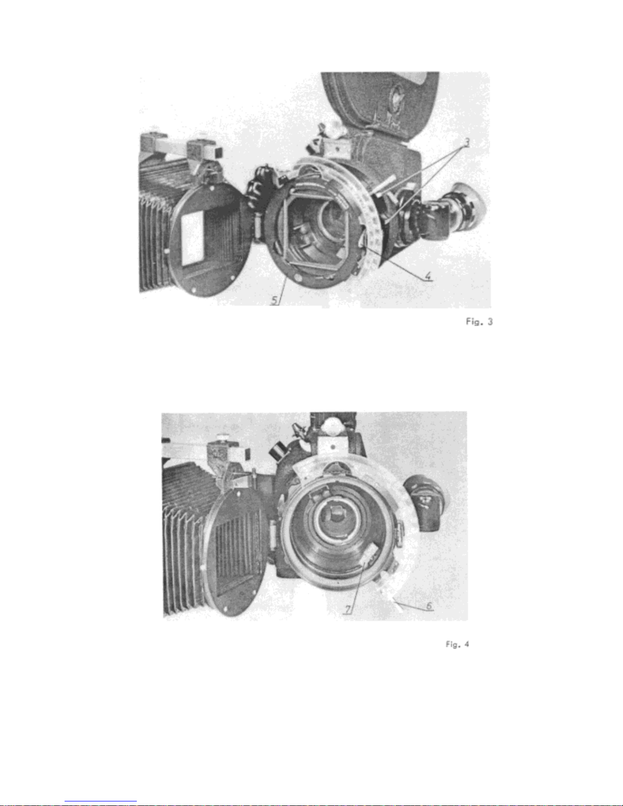
makes certain that the rings are firmly locked together. The lens outer housing is equipped with a
hinge (II/8) so that the frontpart becomes a door (V/3) for the filter holder (V/9). A knurled tension
lock, which catches automatically and can be tightened, presses the filter holder against an elastic
sound – insulation support. To change the filter or plane glass (V/10), the lock is turned counter-
clockwise and the hinged front (V/3) is opened so that the interchangeable filter holder (V/9) can be
taken out. The filter holder contains the filter or plane glass mounted upon an elastic support and
retained by four leaf springs. To change filters, the upper and lower parts of the filter holder (V/9) are
turned against eachother until the two square cut-outs match, the filter is taken out, a new arm put in,
and the process is reversed. Important!: If square filters of up to5 mm thickness are used, the knurled
upper part is to be turned against the lower part in a clockwise direction. If filters thicker than 5mm
are used, the upper part is turned in a counter-clockwise direction to avoid damaging the leaf springs.
When no filter is mounted, the plane glass of the same size must be used. The filter and the plane
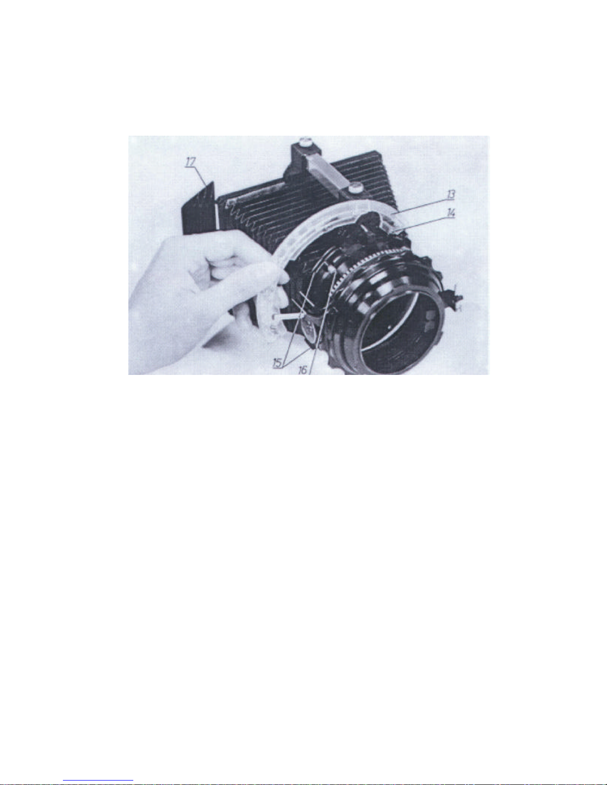
glass however, can never be used together. The adjustable matte box with bellows (II/7) is mounted
upon the hinged front (V/3) by seating it at the lugs (V/1) and locking it with the snap catch (V/2.)
The matte box swings with the hinged front (V/3) when it is opened.
A zoom lens consists of a stationary main lens and an adjustable system of auxiliary lenses. The
latter system is usually of considerable length so that the front lens, because of this, enters into the
focusing range of the main lens. This is especially the case with short focal length settings and small
apertures. For this reason, the front lenses must always be kept especially clean, as foreign particles
could easily show up in the picture. The same applies to the plane glass and filter.
4
A. Removal of the sound-proofed lens
The lock of the outer housing is opened by turning the locking grip (I/5) counterclockwise from the
position FEST to the position LOSE. Then the push button (I/12 a. V/16) is pressed in with the
index finger of the right hand and the sound-proofed lens turned counter- clockwise with the left
hood until it disengages and can be slid out.
B. Mounting the sound-proofed lens
The mark LOSE on the lock of the outer housing (I/5) is matched with the red dot.The sound-proofed
lens is taken in the left hand, plexiglass window up (I/3), and slid with the lens mount and its bayonet
catch into the grooves of the lens socket (V/14) and turned clockwise until it engages, this being
indicated by a slight click. The push button (I/12 a. V/16) need not be depressed while mounting the
lens. Once the lens is locked, the outer housing (V/6) is locked by turning the ring clockwise from
LOOSE to FIX.
5
2. Universal Lens Blimp for ARRIFLEX 16 BL
Fig. I
In conjunction with the Universal Lens Blimp, the following lenses or fixed focal length from the ARRI
Lens Programme can be used for sound – insulated shooting:
Schneider Cinegon F / 1.8 / 10 mm (as from 1967)
Cine-Xenon F / 2 / 28mm
Cine-Xenon F / 2 / 35mm
Cine-Xenon F / 2 / 40mm
Cine-Xenon F / 2 / 50mm
Cine-Xenon F / 2 / 75mm
Zeiss Distagon F / 2 / 8mm
Distagon F / 2 / 16mm
Planar F / 2 / 24mm
Planar F/ 2 / 32mm
Planar F / 2 / 50mm
Sonnar F/ 2 / 85mm
CookeSpeed Panchro T/ 2.2 / 25mm
Speed Panchro T/ 2.3 / 32mm
Speed Panchro T/ 2.3 / 40mm
Speed Panchro T/ 2.3 / 50mm
Speed Panchro T/ 2.3 / 75mm
For various reasons all other lenses in the ARRI Lens Programme cannot be used with the lens
blimp, or only with limitations.
6
1 . The following lenses:
Schneider Cinegon F / 1.8 / 18mm
Cinegon-Xenon F / 2 / 100mm
Zeiss Sonnar F / 4 / 135 mm
CookeSpeed Panchro T / 2.2/ 18mm
Speed Panchro T / 2.8/ 100mm
Kilfitt Makro – Kilar F / 2.8 / 40mm
Makro - Kilar F / 2.8 / 90mm
fit the lens mounting of the ARRIFLEX 16 BL, but will not fit into the UniversalLens blimp, because in
some cases their diameter and in others their overall length is too big. These lenses should therefore
be used only when sound- insulation requirements are not critical, Moreover, lenses with a focal
length in excess of 100 mm need a lens support (in preparation.)
2. The fixed focal length lenses not listed above have too short a back focal distance (distance from
rear element to mirror reflex position.) This point will be taken into account in future lens designs
so that all new models included in the ARRI Lens Programme will also be adapted to the
ARRIFLEX 16 BL.
The Universal Lens Blimp is dimensioned so that, in principle, standard 75 x 75 mm ARRI filters and
3 x 3” Wrattenfilters can be used. These standard filters are large enough for the shortest focal
length used. In view of the short focal lengths, however, filter size is governed by the overall length of
the Universal Lens Blimp and hence by the maximum length of the lenses used.
The filter holders for the two zoom lenses, Angenieux Multifocus 10 x 12 and Zeiss Vario – Sonnar 6
x 12.5, are the same as those for the Universal Lens Blimp and can therefore be used
interchangeably. We recommend the use of a separate holder for each filter. This makes it
considerably easier to keep the filter glasses clean.
The matte box for the Universal Lens Blimp can also be used for the above mentioned blimped zoom
lenses. As from mid- 1967, we will be supplying the some matte box for these lenses as for the
Universal Lens Blimp. The difference from their predecessors is a mirror holder hinge on the front
frame. On request, we supply for the Universal Lens Blimp a rectangular mirror which permits
indirect reading of the focusing aperture scales from a longer distance.
The length of the matte box booms is adopted to the blimped lenses. For Universal Lens Blimp only
the short boom should be used. There are no engraved bellows extension markings, as the focal
lengths of the usable lenses vary.
We deliver lenses ordered from the Universal Lens Blimp ready for installation, i.e. with adjusted
coupling elements calibrated focusing aperture scales, as is the usual practice for big studio blimps.
7
If already available lenses (see list on page 24) are to be used in the Universal Lens Blimp, coupling
modifications and calibration of the focusing aperture scale are necessary. This can be done either
by ARNOLD & RICHTER or in an authorized service workshop. Precise installation and adjustment
instructions are available on request.
1. Universal Lens Blimp, Fig, 2, with the three clamping lugs (Fig. 2/1) in the three grooves on the
camera (as for zoom lenses)l then turn to right until the lens blimp engages the latch (Fig. 2/2)
The matte box is mounted exactly as on zoom lenses.
8
11. Turn the locking ring (Fig. 1/3) to give a firm seating, loosen the. closure of the front door (Fig.
3/4), open the hinged door and remove the filter holder (Fig, 3/5) . Set focusing lever at infinity and
swing out diaphragm driver (Fig. 4/7).
9
III. Turn tens focusing ring(Fig. 5/8) to
Infinity mark, so that the middle of the
retaining pin slot (Fig. 5/9) is opposite
the stop.
IV. Open the catches forlocking the lens by depressing the push button (Fig. 6/10), and insert the
lens in, the bore with the retaining pin slot (Fig. 5/9) uppermost. The focusing driver (Fig . 6/11) of the
lens blimp engages the left leaf(in Fig, 6) of the focusing lever on the lens . The bracket makes
coupling withthe wrong leaf (on the right in Fig. 6/11) of the focusing lever impossible. Swing
diaphragm driver back into place and couple with the diaphragm ring (Fig. 6/12)
Fig. 6
10
V. Insert the filter holder (Fig. 3/5) and close the front door (as for zoom lenses)
VI The focusing aperture scale (Fig.7/13) is attached by slipping it over the pin (Fig. 7/14) and then
pivoting the scale into the slot of the guide elements until it engages the catch pin (Fig. 7/16.) To
remove or replace the scale, the catch pin (Fig.7/16) is pulled out.
Fig. 7
VII. The interchangeable mirror (Fig, 7/17) permits indirect reading of the focusing aperture scale (Fig.
7/13) from a greater distance.
VII. To remove the lens, reverse the above procedure.