Instruction Manual
ARW-DPIT Touch
AS, 02.12.2010 DPIT GB Page 2 of 13
Via M. Pasubio, 137
36010 Zanè (VI)-(Italia)
Tel +39 0445 492313
Fax +39 0445 491365
E-mail:info@strumentieservizi.com
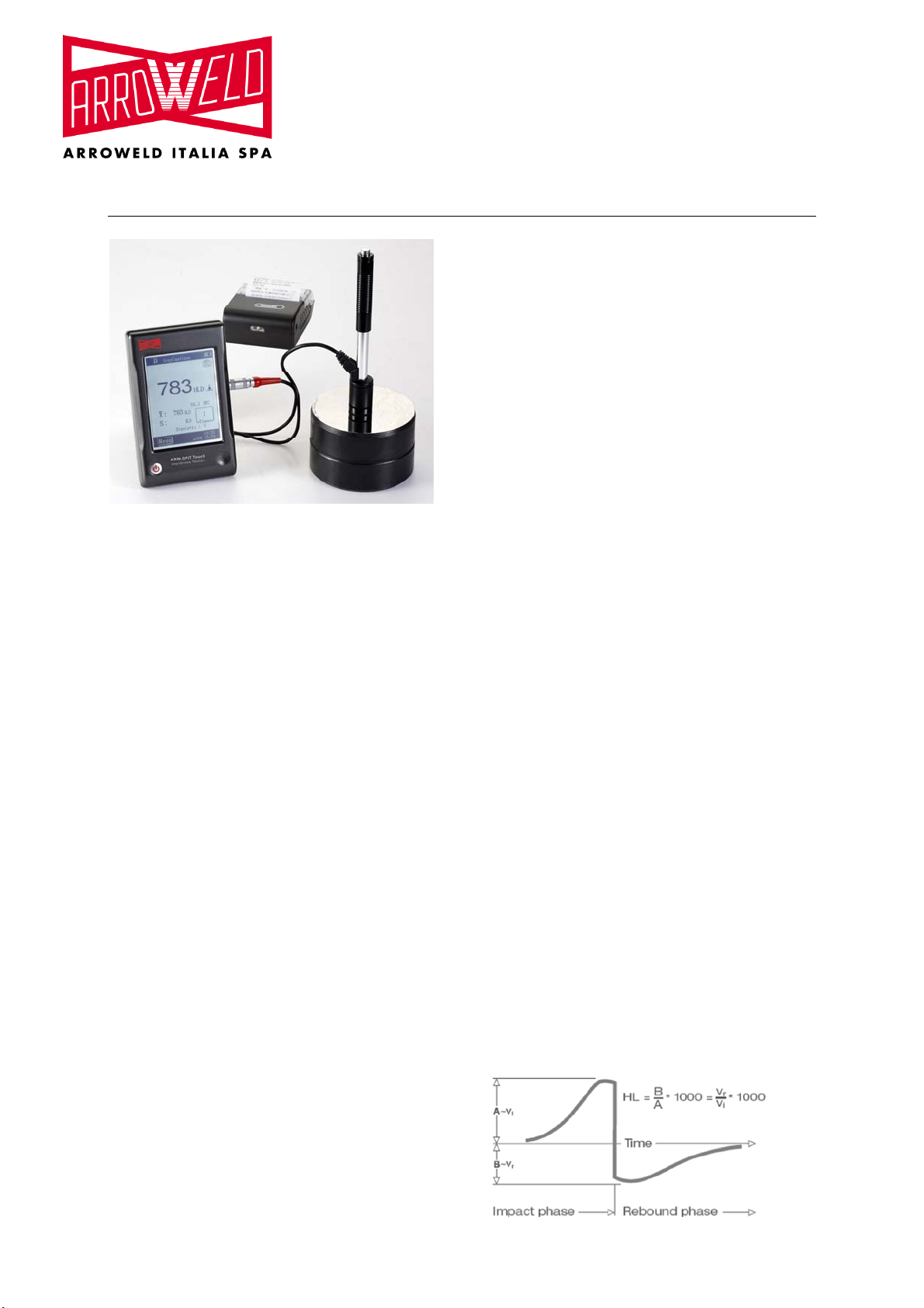
The measuring principle of DPIT Hardness Tester is
physically a rather simple dynamic hardness test:
An impact body with a hard metal test tip is propelled by
spring force against the surface of the test piece. Surface
deformation takes place when the impact body hits the test
surface, which results in a loss of kinetic energy. This
energy loss is calculated by velocity measurements when
the impact body is at a precise distance from the surface
for both, the impact phase and the rebound phase, of the
test. The permanent magnet in the impact body generates
an induction voltage in the single coil of the impact device.
The voltage of the signal is proportional to the velocity of
the impact body. A signal processing by the electronics
provides the hardness reading for display and storage.
Simply said, harder materials produce higher rebound
velocities than less harder ones (higher L- value).
DPIT Hardness Tester provides a direct hardness
measurement within any particular material group (i.e.
steel, aluminium etc.). It can be used as a final test result
without conversion. However, there are established
conversions to other hardness scales in this Hardness
Tester as a comfort for our customers. These conversions
to other scales (HRC, HRB, HB, HV, HSD etc.) are
programmed into the electronics and they can be shown
directly on the display as a test result. All data is stored in
the native L scale to prevent any possible errors with
multiple conversions.
1.2. The Hardness value “L”
This term was introduced 1978 into measuring technology
by Dr. Dietmar Leeb. It contains the quotient for the impact
body’s rebound and impact velocity, multiplied by 1000.
Harder materials produce higher rebound velocity than
less harder ones. With reference to a particular material
group (i.e. steel, aluminium etc.), the L value represents a
direct hardness measurement and is used as such.
Comparison curves with other standard statistic hardness
values have been established (Brinell, Vickers, Rockwell
C, B) for the most prevalent materials, enabling the
L values to be converted into the relevant values by these
procedures. With this hardness tester, such hardness
values can directly be displayed in the hardness scales
HRC, HRB, HB, HV, HSD and tensile strength (MPa).
1.3 Main features
- Highly accurate, ± 6 HL
- Automatic correction for impact direction
- Large, easy to read display with backlight
- User profiles for fast change of all settings
- Operation with Touch Screen
- Large memory with on- screen review of data
- Conversion to all common hardness scales
HRC, HRB, HB, HV, HSD and tensile strength
(MPa).
- Rechargeable Li- ion batteries
- Conforms to the standard ASTM A956-02
1.4 Application range
- Appropriate for all metals
- Ideal for production level testing
- Best suited for on- site testing of heavy, big or
already installed parts
- Handy for difficult to access or confined test
locations
- Automatic compensation for impact direction
- Excellent for material selection and acceptance
tests
- Easy to handle and accurate on curved test
surfaces (R> 10mm)
- Metal production & processing
- Automotive & transportation
- Aerospace & shipyard
- Testing services & laboratories
1.5 Technical information
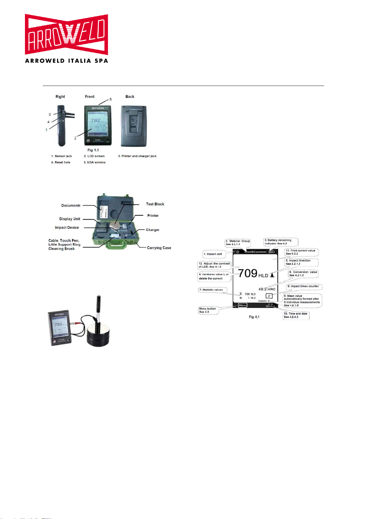
1.5.1 Display unit
HL Display Range: 0 ~ 1000 HL
Accuracy: ± 6 HL
Display of the main body: large LCD with
adjustable contrast, backlight, Touch Screen
Unit Material: shock resistant ABS plastic
Internal Data Storage : ~ 800 measured values
• Resolution: 1 HL; 1 HV; 1 HB; 0,1 HRC;
0,1HRB; 1 HSD; 1 MPa
• Battery type: rechargeable Li- Ion
• Operating temperature: 0°C up to + 50°C
(32°F up to 122°F)
• Storage Temperature: -10°C up to + 60°C
(14°F up to 140°F)
• Humidity: 90 % max.
• Dimension: 135 x 83 x 24mm
(5.3 x 3.2 x 0.9 inches)
• Weight: 228 g
1.5.2 Impact unit D
Impact energy: 11 Nmm
Mass of the impact body: 5.5 g
Test tip diameter: 3 mm
Test tip material: tungsten carbide
Test tip hardness: ≥ 1600 HV
Impact length: 147 mm
Impact maximum diameter: 20 mm
Impact weight: 75 g