Note: .
Please
test
fit
aI/ parts before beginning assembly. The glider'has a complete 3 view drawing separate to this manual.
Please refer to this drawing during assembly.
This.
drawingis the latestinformation abouUhe
glider
imd
shouldbe the
primary
source
forineasurem~nt
and
placementquestions.
.i
'.
,"
,
• . . • " j I . .
Finishing the Wood Surfaces
To
prevent the wood from pre-mature aging and moisture
damage, we recommend sealing the wood using lacquer
manufactured by DEFT (available from The Home Depot and
Lowe's stores). The best would
be
a "Satin" or "Semi gloss"
type
of
finish. (Prior to using lacquer, any white foam surface
should be sealed by applying a film like coat of epoxy). The
black poplar veneer wing skins (-OAmm thick) are sealed
under surface, then laminated with epoxy to the wing foam
cores. This
is
making a barrier preventing harsh lacquer thinner
penetration inside. We recommend
to
apply lacquer
in
a few
very light coats, this way lacquer thinner evaporates very fast
and does not have time to cause any harm to the wing foam
cores. The best finish results will
be
to brush
on
1 0 2 coats
of
Lacquer Sanding Sealer then sand the surface using 400 grit
sand paper, then spray
on
a very light 3-rd, 4-th and more coats
if desired.
Use as little as possible
to
keep the weight down.
Color
Option
:
After wing
is
completely finished with lacquer then you can
mask it and spray some color stripes especially to the bottom
side
of
the wing that will give the glider some accent and
provide you with better visibility during flight.
2
Recommended Building Steps
Attention:
The
ailerons
and flaps
should
remain
uncut
from
the
wing
as
long
as possible. Meaning after wing is finished
and painted it should be put aside for a few days to cure.
The paint curing process and reacting with the wood usually
takes 2-3 days even in a warm environment. During this time
the surface should remain uncut.
(many times modelers are impatient and cut the ailerons/flaps
as
soon
as
the wing
is
dry to the touch)
If the control surfaces are cut from wing shortly after it's painted
then more likely will be distorted during paint curing
It
is
best
to
start
building
the
glider
from
the
wing,
1.
finish both wing tips
2. glue together wing center panels and laminate the joint.
3. paint the wing (including personal touches) to its final stage
and put the wing aside to cure the paint (longer time is better)
4.
assemble and paint the glider tail
5.
assemble fuselage with tail, install pushrods, radio gear and
electric drive components
in
the fuselage.
(those steps usually take 2-3 evenings sometimes longer -this
is
also valuable time needed to cure painted wing)
6. cut wing servo bays and prepare them for servo installation.
7. now separate the ailerons from the wing, finish them and
hinge to the wing as soon
as
possible.
8. separate the flaps from the wing, finish them and hinge to the
wing as soon as possible.
(do not leave control surfaces unattached to the wing for a
longer period
of
time)
9. install aileron and flap control horns
10. Prepare wing servo wiring and install wing servos.
Notesaboutthefinishedsurfaces:
The fuselage is painted (in the mold). The white
paint
will be
damagedbythinners. The woodsurfaces
cC)n
be finishedwith a
proper
clear
varnish.
Remember
tha(the wing has a foam core
and
somepaints
may
attackthefoam internaily.
.;
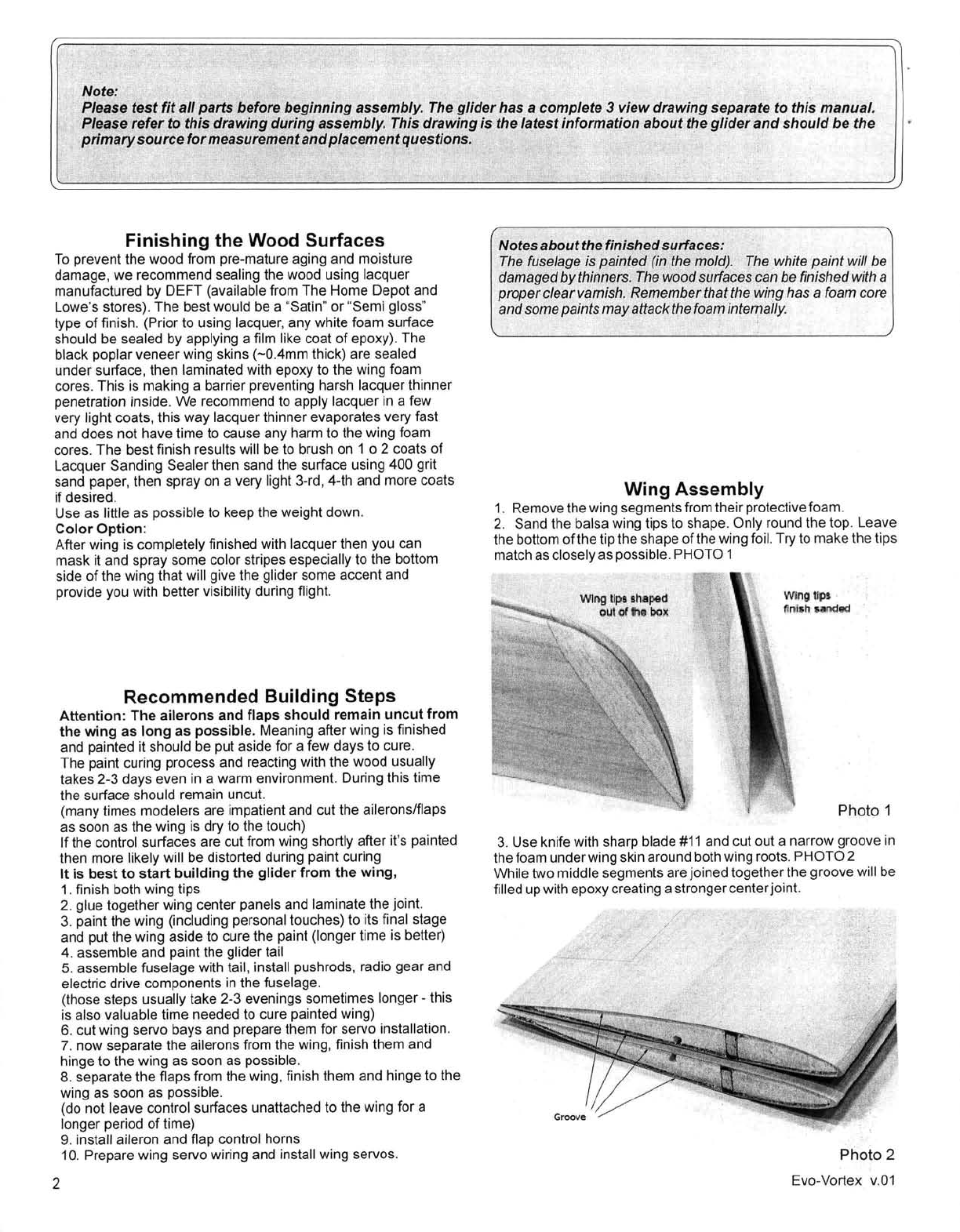
Wing Assembly
1. Remove the wing segmentsfrom their protectivefoam.
2. Sand the balsa wing tips to shape. Only round the top. Leave
the bottom
of
the tip the shape ofthe wing foil. Try to make the tips
match
as
closely as possible. PHOTO 1
Wing
uP' .
~
ml
h.
51!l11ded
Photo 1
3. Use knife with sharp blade
#11
and cut out a narrow groove
in
the foam underwing skin around both wing roots.PHOTO 2
While two middle segments are joined together the groove will be
filled up with epoxy creating a strongercenterjOint.
Photo 2
Evo-Vortex v.
01