Art Hobby Sierra-S 2.5M User manual

Assembly Manual
Note: This plane can be flown “full house” with a computer ra-
dio to maximize its performance potential. However, this plane
can be flown in several other configurations with more basic
radio systems.
3 channel single stick: ailerons, flaps and elevator
(uses a Y-harness for the ailerons and the flaps)
3 channel two stick: ailerons, flaps and elevator
(Uses a Y-harness for the ailerons and flaps)
4 channel two stick: ailerons, flaps, elevator and rudder (with
the use of a V-tail mixer for the rudd/elev and Y-harnesses for
the flaps and ailerons)
5 channel two stick: ailerons, flaps, elevator and rudder (with
the use of a V-tail mixer for the rudd/elev, two chennels for aile-
rons and Y-harnesses for the flaps )
6 channel two stick: ailerons, flaps, elevator and rudder (with
the use of a V-tail mixer for the rudd/elev, two chennels for aile-
rons and two chennels for the flaps )
Sierra-S 2.5MSierra-S 2.5M
Sierra-S 2.5M
The Sierra is a 2.5M F3F Racer featuring a RG15 airfoil.This full house sailplane can be flown both on the slope or as a thermal ship. Its Kevlar
reinforced spar system makes the wing strong enough for high speed flight and winch launching. Experienced flyers will appreciate the
Sierra’s beautiful craftsmanship and materials as well as its exciting flight performance. European sailplane champions recognize the Sierra
as a formidable competitor. Sport fliers appreciate its wide flight envelope.
However, do not choose the Sierra as your first airplane
. We hope
you enjoy your new Sierra
Kit Contents
) Wing - Four Segments
) Fiberglass Fuselage
) Fiberglass Nose Cone
) Fiberglass Inner Nose Cone
) V-Tail Stabilizers with Control Surfaces
) V-Tail Shaped center plate 15mm x 90mm
) Plywood Plate 3mm x 15mm x 17mm (qty.2)
) Wing Screw Block 30mm x 20mm square (qty.3)
) Heavy Duty Towhook
) M2 N V-tail Bolt and Nuts (qty.2)
) M5 Nylon Wing Bolt (qty.3)
) 5mm Wing Nut (qty.3)
) Flat Nylon Horns (2 left and 2 right)
) Angled Nylon Horns (1 left and 1 right)
) Carbon rods Ø 6mm (qty.4)
) Fiberglass Cloth (heavy weight for the wing center joint,
light weight for reinforcements of the V-tail and face surface
of the wing panels)
SierraS v.03
Recommended Tools, Supplies
and Accessories:
- Hobby Knife (blade #11)
- 5 Minute Epoxy (#A0201).
(use for joining the wing panels and tail)
- 20 Minute Finishing Epoxy (#A0209)
(use for fiberglassing the joints)
- CA adhesive (#A0101).
- Masking tape
- Pliers
- Drill
- Drill Bits: 2mm, 4mm, 6mm
- Soldering Iron
- 1 meter ruler
- Flexible metal ruler (Approximately 200mm long will be
easiest to use)
- Covering Trim to customize the color scheme.
- 2 x 24” and 2 x 36”servo wire extensions
(#H00X24 & H00X36)
or 100 Inches of Servo Wire to make your
own extensions
- Universal wing servo covers (#A0031)
- Clear lacquer (DEFT)
Art Hobby guarantees this kit to be free from defects in material and
workmanship, at the date of purchase. This does NOT cover any
components damaged by use, misuse, or modification. In no case
shall Art Hobby’s liability exceed the original cost of the purchased
product. In that Art Hobby has no control over the final assembly or
material used for final assembly, no liability shall be assumed for
any damage resulting from the use by the user of the final user-
assembled product. By the act of using the final user-assembled
product, the user accepts all resulting liability. Radio Control Hob-
bies are not toys but rather high performance models that could
produce harm. Always put safety first when using this product.
If this is your first model, please seek
the advice of other experienced
modelers prior to assembly and
flight. An internationally recog-
nized nonprofit sanctioning orga-
nization for modeling is the Acad-
emy of Model Aeronautics.They can
provide club, field, and liability in-
surance information. Contact them
for information at:
AMA
5151 East Memorial Drive
Muncie, IN 47302-9252
(800) 435-9262
Fax: (765) 289-4248
Internet:
www.modelaircraft.org
Check the Items Needed,Tools and
Supplies, and Contents sections.
Verify the contents of the kit and
your supplies before continuing.
If you have any other problems or
questions, please contact customer
service in the U.S.A. at:
Customer Service
1122 Ginger Ave.
Billings, MT 59105
(406) 545-4118
Email:
gliders@arthobby.com
Visit us at
www.arthobby.com
Note about the Fiberglass: The white finish on the epoxy
glass fuselage is paint. Chemicals such as alcohol, acetone,
and paint thinner will attack the paint.

Note: Please test fit all parts before beginning assembly.The Sierra has a complete 3 view assembly drawing separate to
this manual. Please refer to this drawing during assembly. This drawing is the latest information about the Sierra and
should be the primary source for measurement and placement questions.
2.
Wing Assembly
1. Remove the wing segments from their protective foam.
2. Sand the balsa wing tips to shape. Only round the top. Leave the
bottom of the tip the shape of the wing foil. Try to make the tips
match as closely as possible. PHOTO 1
Find the light fiberglass cloth and cut four ~35 - 40mm wide
strips from it. PHOTO 2
3. Lightly sand the meeting surfaces of the wing center panels and
outboard panels.
4. Apply the 40mm wide gloss cloth strip to each panel face. Use 20
Minute Finishing Epoxy to adhere the glass cloth strips to the panel
face. PHOTO 3 Do NOT use polyester resin as the resin will
attack the foam core.
5. After epoxy has cured cut off excess cloth and sand finish using
400-grid sanpaper, than cut through it to expose the holes for the
Carbon fiber rods and the cable canals.
6. Glue the four (100mm) carbon fiber rods in the outboard
wing panels, with the exposed ends projecting out 50mm.
PHOTO 4
PHOTO 1
PHOTO 2
PHOTO 3
Recommended building steps
Attention: The ailerons and flaps should remain uncut from the
wing as long as possible. Meaning after wing is finished and
painted it should be put aside for a few days to cure.
The paint curing process and reacting with the wood usually
takes 2-3 days even in a warm environment. During this time the
surface should remain uncut (many times modelers are
impatient and cut the ailerons/flaps as soon as the wing is dry to
touch). If the control surfaces are cut from wing shortly after it’s
painted then more likely will be distorted during paint cureing
It is best to start building the glider from the wing,
1. finish both wing tips
2. glue together wing center panels and laminate the joint.
3. paint the wing (including personal touches) to its final stage
and put the wing aside to cure the paint (longer time is better)
4. assemble and paint the glider tail
5. assemble fuselage with tail, install pushrods, radio gear and
electric drive components in the fuselage.
(those steps usually take 2-3 evenings sometimes longer - this
is also valuable time needed to cure painted wing)
6. now separate the ailerons from the wing, finish them and
hinge to the wing as soon as possible.
7. separate the flaps from the wing, finish them and hinge to the
wing as soon as possible.
(do not leave control surfaces unattached to the wing for a
longer period of time)
8. cut wing servo bays and prepare them for servo installation.
9. install aileron and flap control horns
10. Prepare wing servo wiring and install wing servos.
Finishing the Wood Surfaces
To prevent the wood from pre-mature aging and moisture damage,
we recommend sealing the wood using lacquer manufactured by
DEFT (available from The Home Depot and Lowe’s stores). The
best would be a “Satin” or “Semi gloss” type of finish. (Prior to
using lacquer, any white foam surface should be sealed by
applying a film like coat of epoxy). The black poplar veneer wing
skeens (~0.4mm thick) are doped under surface then laminated
with epoxy to the wing foam cores. This is making a barrier pre-
venting harsh lacquer thinner penetration inside. We recommend
to apply lacquer in a few very light coats, this way lacquer thinner
evaporates very fast and does not have time to cause any harm to
the wing foam cores. After applying the first and second light coats,
sand the surface using 400 grid sand paper, then apply a very light
3-rd, 4-th and more coat if desired. Use as little as possible to keep
the weight down.
Color Option:After wing is completely finished with lacquer then
you can mask it and spray some color stripes especially to the
bottom side of the wing that will give the glider some accent and
provide you with better visibility during flight.
Spray on lacquer is the best way to finish wings of our gliders.
We do not recommend using any heat-on covering materials
(potential heat damage).
SierraS v.03

The cloth will reinforce the wing, top and bottom, around the
wing joint at the root.
To help hold the glass in place while the epoxy resin is applied, first
apply C/A glue to the glass at the leading edge, then pull the glass
smooth and apply C/A glue to the glass at the trailing edge.
11. To keep the resin from spreading too far, apply masking tape to
the wing ~2mm away from the cloth’s edge. PHOTO 6
12. Mix a moderate portion of 20min.epoxy and using a small paint
brush or spreader stick apply the epoxy to the bottom of the joint.
13. Lay prepared strips of glass cloth over the joint.
First lay the heavy cloth then the medium wider strip over.
PHOTO 7
14. Use small piece of paper towel, fold a few times together and
dab the gloss cloth.
15. Dabbing will allow the epoxy to completely saturate the cloth
and adhere to the wood wing surface, it will also remove excess
epoxy and smooth the joint. PHOTO 8
PHOTO 7
PHOTO 8
3.
PHOTO 4
PHOTO 6
SierraS v.03
Joining the Wing Center Panels
1. Hold the wing center panels together with masking tape.
Mark the bottom side root of the wing 40mm and 160mm back from
the leading edge. Also mark the position of the wing servo wire
cannals on the bottom side of the wing root .
2. Find the two hardwood blocks.
Place the blocks on the wing root foam surface. Center each block
on the mark you made. Mark the block width on the wing root foam
and draw the wing contour line on the block.
3. Remove the masking tape. Cut out cavities in the wing foam
cores to accommodate the blocks.
4. Shape the blocks before installation and test fit.
Use sandpaper and/or a knife and/or a rotary tool to completely fit
the blocks to the wing’s contour. PHOTO 5
80 mm
Wing Root
FIG. 1
Make a wood support or use books to hold the tip at its proper
height.
9. Allow the epoxy to cure (at least 30 minutes) then clean the joint.
10. Cut two srips 35mm wide from heavy weight glass cloth, and
two strips 50mm wide from medium weight glass cloth (supplied in
the kit). PHOTO 6
PHOTO 5
To achieve a proper fit, the root of each wing half must be sanded
at a slight angle to fit.
6. After sanding the wing root surfaces trial fit the blocks once again.
It may be necessary to make adjustments to the wing blocks.
7. Lay down wax paper to protect your work bench.
8. Once satisfied with the fit, glue the blocks in place and wing
center panels together. Use 5 Minute Epoxy and hold the wing
panel in place. Wipe away any excess epoxy.
Hold down both center panels together at the rots and raise the left
wing tip 80mm from the table surface. FIG 1

Wing Installation
The wing is bolted to the fuselage with three 5mm nylon bolts
and blind nuts. The bolts are inserted through the hardwood
blocks in the wing. It is important that the wing bolts are posi-
tioned through the middle of the blocks. It is also important to
properly glue the plywood plates securely inside the fuselage.
Please thoroughly read through this section before beginning
assembly.
1. Find the wing, fuselage, nylon wing bolts, and plywood plates.
2. Mark the bolt hole positions on the top of the wing. The holes
should be positioned 15mm from the wing root, and should be
centered over the block. To check your work, measure the distance
between the holes (from front to back).The holes should be 150mm
apart.
3. Through the WING ONLY, use the marks you made as a guide to
drill 5mm diameter holes for the wing bolts. The holes should be
drilled perpendicular to the top of the wing.
4. Test fit the wing on the fuselage. It should be leve on the fuselage
and perpendicular (90 degrees) to the fuselage centerline.
5. Mark the hole position on the fuselage wing saddle for the wing
bolts. By marking the holes to match the holes you just drilled, you
are assured a perfect match.
6. Open an acess hole on the top of the wing saddle. The hole
should be 40mm wide and 90mm long. Center the hole between
the screw positions. We suggest using a rotary tool and a sanding
drum to make the hole.
7. Double check the hole positions on the fuselage.
Open the holes with a 5mm drill bit.
8. Insert the wing bolts into the wing and place the wing on the
fuselage. Check that the wing is now properly centered on the
fuselage.
9. Locate the two plywood plates. These plates will support the
blind nuts in the fuselage.
10. Trim the edge of the plate to fit under the wing saddle.Test fit the
plates in the fuselage.
11. Glue the plates in position with 5 minute epoxy.
12. Once the glue dries, use a 7mm drill bit to open the holes for the
blind nuts.
13. Insert the blind nuts. Install the wing bolts (with the wing in
position).
14. To set the blind nuts in position, glue them in place with epoxy.
4.
Tow Hook Installation
1. If you have decided to install the towhook, you will need a 4mm
blind nut and 1/4 inch 5 ply plywood, 3/4 inch wide by 3 inches
long.
2. The Towhook is located 63mm behind the wing’s leading edge.
3. Shape the 1/4 inch plywood strip to match the fuselage curves.
4. Install the plywood over the towhook position (inside the fuse-
lage) with a generous portion of 5 minute epoxy.
5. Once the glue has set, drill a 4mm hole for the towhook.
6. Open the hole in the plywood for the blind nut.
7. Install the blind nut and the towhook.
Wing Servo and Control
Surface Installation
Refer to glider drawing and check the marking of the aileron and
flap location on each wing.
1. Cut the aileron and flap from the wing.
First cut both ends of each aileron and flap. We recommend using
a fine balsa saw to make those cuts. Use hobby knife with #11
blade and metal ruler as a cutting guide to cut the ailerons and
flaps from the wing.
It is very important to make perfectly straight cuts.
2. Because the ailerons will be hinged on the upper wing surface,
the leading edge of each aileron will need to be sanded at an
angle to allow the aileron to deflect down.
The flaps will be hinged on the lower wing surface.
3. Use hinge tape (or silicone hing) to attach the ailerons and flaps
to the wing.
4. The wing flap servo bays 40mm x 35mm are located 320mm in
from the wing root, and 100mm from the trailing edge.
5. The wing aileron servo bays 40mm x 35mm are located 775mm
in from the wing root, and 90mm from the trailing edge. Please use
Hitec HS-85 servos for the ailerons, and HS-85MG servos for the
flaps or similar wing servos. Make an exact cut in the bottom of the
wing for the servos. Align the servo so that the output arm is aligned
with the aileron or flap.
6. Run servo wire through the wing (music wire can be used to help
pull the wire through) Hardwire the servo wire extension to the
servo. There is simply no room for the servo plug. Be very careful to
keep the polarity correct and each wire insulated.
7. Connect the servos to the receiver. Turn on the radio and center
the servos. Check for proper servo movement - use servo reversing
switches on the transmitter if the servo turn in the wrong direction.
8. Install control horns on the ailerons and flaps directly back from
the servo arm. The horns should be positioned with the holes for-
ward and aligned over the hinge line. Use a small dab of epoxy or
CA to permanently secure the horns in position.
9. Place the servos in the center of servo bays, lock the ailerons
and flaps in a neutral position securing both ends of each control
surface to the wing’s trailing edge with a piece of tape.
PHOTO 9
SierraS v.03
Now measure distances between servo control arms and aileron,
and also the flap control horns, according to these measurments
make two sets of short pushrods from the supplied wire (we sug-
gest making “Z” bend on both ends).
10. Connect the pushrods first to the aileron and flap horns, then to
the servo arms, after that install the servos in servo bays with a
small amount of silicone sealer.
11. To cover the servos you can use Art Hobby’s universal wing
servo covers (#A0031) PHOTO 9
(change new the towel if needed)
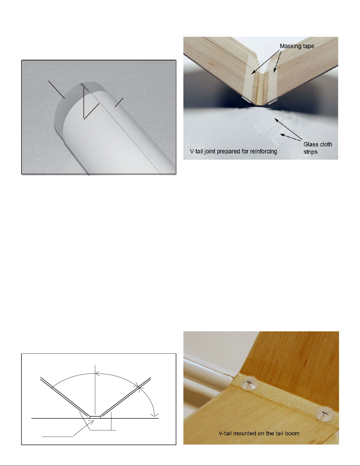
16. Repeat steps 11-14 and apply reinforcing cloth to the top of the
joint.
17. Once the epoxy has set, remove the masking tape.
Apply fresh masking tape 2mm past the end of epoxy.
18. Use 400 grid sand paper and sand the joint smooth if needed.
Do NOT sand away the wingsheeting where the glass ends.
This will weaken the wing and could cause failure.

Inner Cone
Outer Cone
Align Center Mark
you made with the
outer nose cone
seem.
PHOTO 10
Inner Nose Cone Installation
1. Remove the inner and outer nose cone.
Keep track of the nose cone orientation. It will fit upside down (but
will not look very good.)
2. Mark the top of the inner cone at the back edge. PHOTO 10
Front View Centerline
Flat Table
37.5
52.5 Degrees
Stabilizers
Joiner
FIG. 2
3. Slide the inner cone into the outer cone as far as it will go.
4. Mark the inner cone where the outer cone ends.
5. Lightly sand the mating surfaces of the cone and fusealge to give
better adhesion when you glue them together.
6. Glue the cone into the fuselage (using the markings as align-
ment guides) use 5 minute epoxy. Wipe away any excess epoxy.
7. Before the glue dries, trial fit the outer nose cone.
This will ensure perfect alignment.
Do not let any epoxy touch the outer cone!
8. The outer cone slides over the inner cone to close the fuselage.
Use a quality plastic tape (electrical tape works well) to hold the
outer nose cone onto the fusealge.
5.
V-tail Assembly
The V-tail can be glued permanently to the boom with use of
the mounting plate or it can be made removable.
1. Find the V-tail stabilizer halves and the joiner plate.
2. The joiner is pre-cut to the correct angle. However, you should
use a protractor to check your work. Trial fit the parts.
Trim the joiner at the leading edge to match the stabilizers. The
back of the joiner should be aligned with the hinge-line.
3. You may wish to block the stabilizers to hold the correct angle.
The V-angle is 105 degrees. FIG. 2
Do not allow the parts to be twisted. Once satisfied with the fit, join
the parts with CA+ or 5 minute epoxy.
4. Once the glue has set, reinforce the top and bottom of the joint
with strips fiber-glass cloth. PHOTO 11
PHOTO 11
5. Test fit the stabilizer on the fuselage.
The hinge-line should align with the end of the fuselage.
6. If you have chosen to permanently attach the V-tail to the fuse-
lage, lightly sand the fiberglass where the stabilizer attaches to the
fuselage. Glue the stabilizer in place on the fuselage with 5 minute
epoxy.
8. If you have chosen to make the V-tail removable, use the follow-
ing steps:
Mark the middle of the joiner plate (from front to back.)
Now make marks to locate the mounting screw positions (20mm
from the front and 20mm from the back in the middle of the joiner).
9. Drill the two 2mm holes for the mounting bolts.
10. Hold the V-tail in position on the fuselage. Mark and drill the
holes in the fuselage to match the holes in the joiner.
11. Find the two small plywood plates and drill holes in the center of
each wood plate.
12 Find two M2 screws and nuts, use vaseline or grease to fill up
the nut hole then glue the nut to each plate (over the hole)
13 Now install these plates in the fuselage under the saddle holes.
Use 5 minute epoxy.
14. After epoxy sets it’s good to use M2 tap to clean threads in the
nuts.
15. Install the V-tail with the M4 bolts to check aligment, then re-
move it.
17. Enlarge the holes in the V-tail mounting plate to fit in the nylon
retainers. Then reinstall the V-tail. PHOTO 12
PHOTO 12
SierraS v.03

2. Bolt the wing and tail onto the Sierra.
3. Check the balance. Move the battery and servos to acheive a
close balance. Slide the nose cone on. This minimized the amount
of weight that may be needed to properly balance the plane.
4. Check your servo placement. Make sure the servos do not inter-
fere with the removal of the battery.
5. Install the servos with the servo plywood tray - we recommend
(or other method you prefer.) It is important to use epoxy glue the
tray. Other glues will not stick to the epoxy glass fuselage.
6. The receiver and battery should be mounted with foam tape and/
or protective foam. This helps prevent damage on those difficult
landings.
7. Slide the pushrods and pushrod housings you’ve chosen for the
V-Tail. For rudder/elevator control, use a pushrod for each servo.
For elevator only, use one pushrod. At the end of the pushrod, you
will need to make a Y-shaped pushrod joiner to connect the eleva-
tors. PHOTO 14
Control Horns
Mounting Screw
FIG. 3
6.
Radio and Pushrod Installation
Remember, if you are using the V-tail as both elevator and rud-
der, you will need two servos.
If you are just using it as elevator, you will only need one servo.
1. As with most sailplanes, start with the battery in the nose, then
the receiver, then the servos behind. PHOTO 13
PHOTO 13
8. Once the pushrod placement is finalized, secure the housings
with epoxy to prevent flexing.
9. Before flight, double check balance and control throw direction
for free and proper movement.
10. Try some hand launches and straight glides over a grass field
before high launching the glider.
This is a good time to adjust control throws and final balance.
Starting control throws:
AILERONS: 15mm UP, 10mm DOWN, 17 - 26mm CROW
SPOILERON: 26mm UP (break)
FLAPS: 7mm TOWING, 20 - 26mm CROW
ELEVATORS : 8 degrees in each direction
RUDDER: 7 - 12 degrees
Note: Control throws are quite subjective according to the pilot’s
preferences. These throws are simply a starting point. Experimen-
tation is recommended to achieve a smooth flying plane you are
comfortable flying.
Balance Point
The completely assembled glider must balance level when raised
at the marked “C.G” point under the wing roots, a tolerance of 5mm
back and forward from the marked position is permitable.
It is important that the glider is balanced properly. Balance the
SIerra ~80mm back from the leading edge of the wing at the center
section.
Installation of V-tail
Control Horns
1. Find the control horns. The horns for the V-tail are angled to
properly align the elevators to the fuselage. FIG. 3
Cut the backplate from the horns, use them as templates to mark
placement of the holes.
2. Drill holes for the horn locating pins.
3. Mount the horns securing them with the backplates.
Use a small dab of epoxy or CA to permanently secure the horns in
their positions.
PHOTO 14
SierraS v.03
Table of contents
Other Art Hobby Toy manuals
Popular Toy manuals by other brands

PLAYTIVE JUNIOR
PLAYTIVE JUNIOR 290662 Instructions for use

V-tech
V-tech Sit-to-Stand Learning Walker user manual

Step 2
Step 2 Custom Kitchen 8284 manual

V-tech
V-tech Sort & Recycle Ride-On Truck instruction manual

Step 2
Step 2 Art Easel Desk quick start guide

V-tech
V-tech Sing and Splash Fish user manual

Step 2
Step 2 Wild Whirlpool Water Table 8401 manual

V-tech
V-tech Stack & Balance Teeter Totter Parents' guide

V-tech
V-tech Learn & Dance Dino Parents' guide

V-tech
V-tech Myla The Magical Make-Up Unicorn Parents' guide

V-tech
V-tech Turn & Learn Driver user manual

PLAYTIVE JUNIOR
PLAYTIVE JUNIOR PLAY SUPERMARKET 285627 Instructions for use