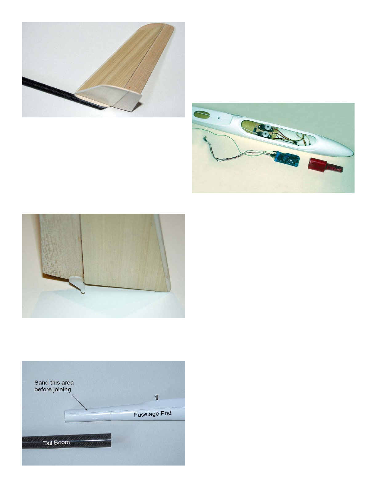
V-tail Assembly
The V-tail can be glued permanently to the boom with use of
the mounting plate or it can be made removable.
1. Find the V-tail stabilizer halves and the mounting plate set.
PHOTO 10
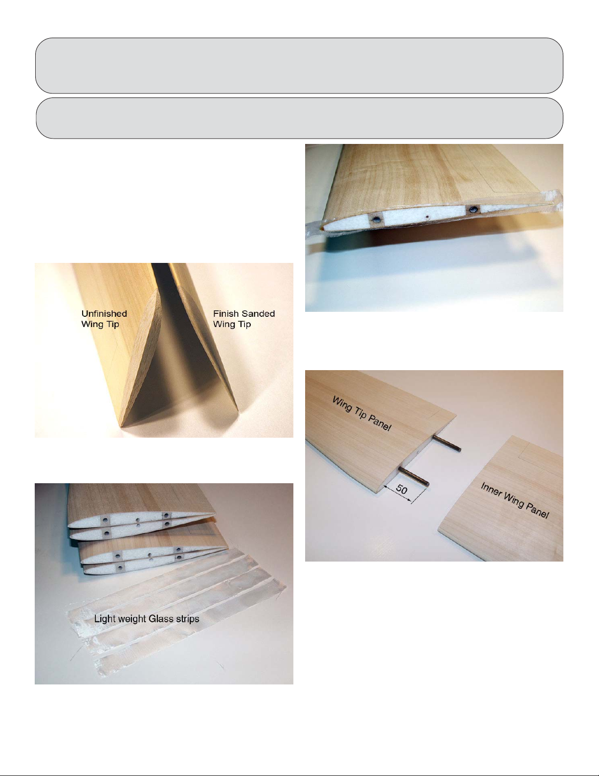
Mounting the Wing
1. Place the wing properly on the fuselage wing saddle, then use a
sharp pointed pencil to mark the wing’s trailing edge on the fuse-
lage.
2. Remove the wing, then measure the distance between the marked
line and the center of the two threaded holes in the wing saddle.
3. Place the wing upside down and transfer both measured dis-
tances onto the center of the wing joint.
4. Using 4mm drill bit, drill the hole in the marked position.
Remember that the hole has to be drilled in an angle to match
the angle of the wing bolt screwed into the fuselage.
5. Find the M4 stainless wing bolt.
6. From the top side of the wing open the holes properly to fit in the
nylon seats for the wing bolts. Trial fit the the seats, insert the wing
bolts, and screw the wing to the fuselage.
If satisfied with the fit, remove the wing and permanently glue wing
bolt seats in place. Use 5 Minute Epoxy
4.
Wing Servo and Control
Surface Installation
Refer to glider drawing and check the marking of the aileron and
flap location on each wing.
1. Cut the aileron and flap from the wing.
First cut both ends of each aileron and flap. We recommend using
a fine balsa saw to make those cuts. Use hobby knife with #11
blade and metal ruler as a cutting guide to cut the ailerons and
flaps from the wing. It is very important to make perfectly straight
cuts.
2. Because the ailerons will be hinged on the upper wing surface,
the leading edge of each aileron will need to be sanded at an
angle to allow the aileron to deflect down. The flaps will be hinged
on the lower wing surface.
3. Use hinge tape (or silicone hing) to attach the ailerons and flaps
to the wing.
4. The wing flap servo bays 40mm x 35mm are located 320mm in
from the wing root, and 100mm from the trailing edge.
5. The wing aileron servo bays 40mm x 35mm are located 775mm
in from the wing root, and 90mm from the trailing edge. Please use
Hitec HS-85 servos for the ailerons, and HS-85MG servos for the
flaps or similar wing servos. Make an exact cut in the bottom of the
wing for the servos. Align the servo so that the output arm is aligned
with the aileron or flap.
6. Run servo wire through the wing (music wire can be used to help
pull the wire through) Hardwire the servo wire extension to the
servo. There is simply no room for the servo plug. Be very careful to
keep the polarity correct and each wire insulated.
7. Connect the servos to the receiver. Turn on the radio and center
the servos. Check for proper servo movement. Use your servo re-
versing switches on the transmitter if the servo moves in the wrong
direction.
8. Install control horns on the ailerons and flaps directly back from
the servo arm. The horns should be positioned with the holes for-
ward and aligned over the hinge line. Use a small dab of epoxy or
CA to permanently secure the horns in position.
9. Place the servos in the center of servo bays, lock the ailerons
and flaps in a neutral position securing both ends of each control
surface to the wing’s trailing edge with a piece of tape. Now mea-
sure distances between servo control arms and aileron, and also
the flap control horns, according to these measurments make two
sets of short pushrods from the supplied wire (we suggest making
“Z” bend on both ends).
10. Connect the pushrods first to the aileron and flap horns, then to
the servo arms, after that install the servos in servo bays with a
small amount of silicone sealer.
11. To cover the servos you can use Art Hobby’s universal wing
servo covers (#A0031).
The plate and triangle are pre-cut to the correct angle of 105 de-
grees. All tail pieces: the mounting plate, two V-tail halves, and
triangle interlock together.
2. The mounting plate and triangle are a little bit longer, so both
pieces have to be cut to fit. At the back it should aligned with the
hinge line. The front should match the stabilizer.
3. After cutting the front and the back of the mounting plate and
triangle, they should be sanded to shape. PHOTO 11
PHOTO 10
PHOTO 11
Serenity v.11/2005
(change new piece of the towel if needed)
16. Repeat steps 11-15 and apply reinforcing cloth to the top of the
joint.
17. Once the epoxy has set, remove the masking tape. Apply fresh
masking tape 2mm past the end of epoxy.
18. Use 400 grid sand paper and sand the joint smooth if needed.
Do NOT sand away the wingsheeting where the glass ends.This
will weaken the wing and could cause failure.