Art Hobby Momentum-DL 1.5M User manual


2
Recommended Building Steps
Attention: The ailerons should remain uncut from the wing
as long as possible. Meaning after wing is finished and
painted it should be put aside to cure. The paint curing process
and reacting with the wood usually takes 2-3 days even in a
warm environment. During this time all surfaces should remain
uncut. (many times modelers are impatient and cut the
ailerons/flaps as soon as the wing is dry to the touch)
If the control surfaces are cut from wing shortly after it’s painted
then more likely will be distorted while paint curing.
We recommend to start building the glider from the wing:
1. finish both wing tips
2. cut and box wing servo bays preparing for servo installation.
3. glue together wing center panels and laminate the joint.
4. paint the wing (including personal touches) to its final stage
and put the wing aside to cure the paint (longer time is better)
5. prepare wing servo wiring and.
6. assemble the glider tail
7. assemble fuselage with tail, install push-rods and servos in
the pod. (those steps usually take 1-2 evenings - this is also
valuable time needed to cure painted wing)
8. separate ailerons from the wing.
9. install aileron servos and control horns and finis wiring.
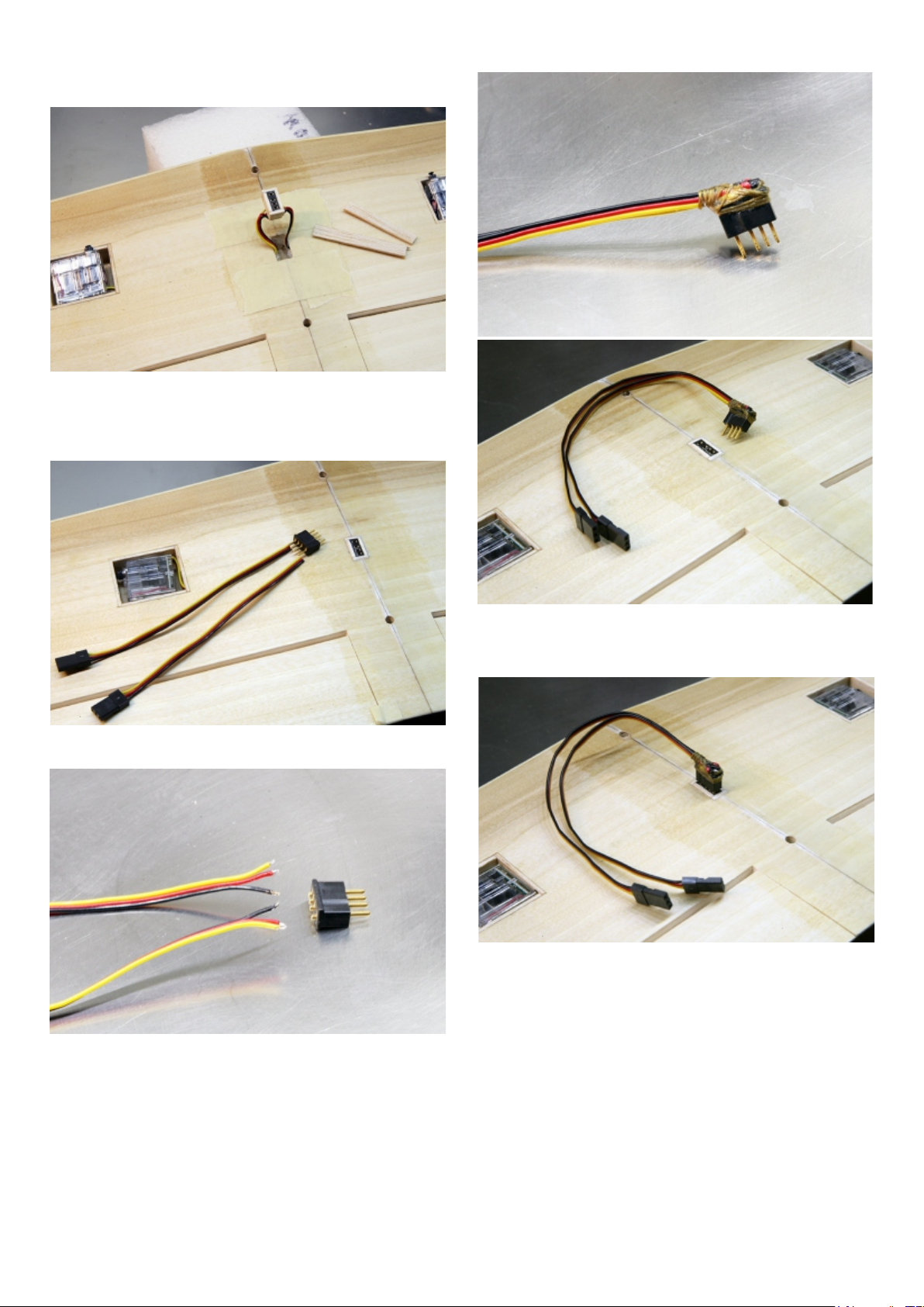
Wing Tips
1. Remove the wing segments from their protective foam.
2. Sand the balsa wing tips to shape. Only round the top. Leave
the bottom of the tip the shape of the wing foil. Try to make the tips
match as closely as possible. Photo 1
Finishing wing Wood Surfaces
To prevent the wood from pre-mature aging and moisture
damage, we recommend sealing all wood surfaces using
lacquer manufactured by DEFT (available from ACE Hardware
stores or Lowe’s).
(Prior to using lacquer, any white foam surface should be
sealed with epoxy). The black poplar veneer wing skins
(~0.4mm thick) are sealed under surface, then laminated with
epoxy to the wing foam cores. This process is making a barrier
preventing harsh lacquer thinner penetration inside.
We recommend to apply lacquer in very light coats, this way
lacquer thinner evaporates very fast and does not have time to
cause any harm to the wing. The best finish result is achieved
by brushing 2 light coats of Lacquer Sanding Sealer then sand
surface after second coat using 400 grit sandpaper, then spray
on a very light finishing coat if desired - use as little as possible
to keep the weight down.
Color Option: After wing is completely finished with lacquer
you can mask it and spray some color stripes, especially to the
bottom side of the wing. This will give the glider some accent
and provide you with better visibility during flight, especially
high altitude thermal gliding. P. 1
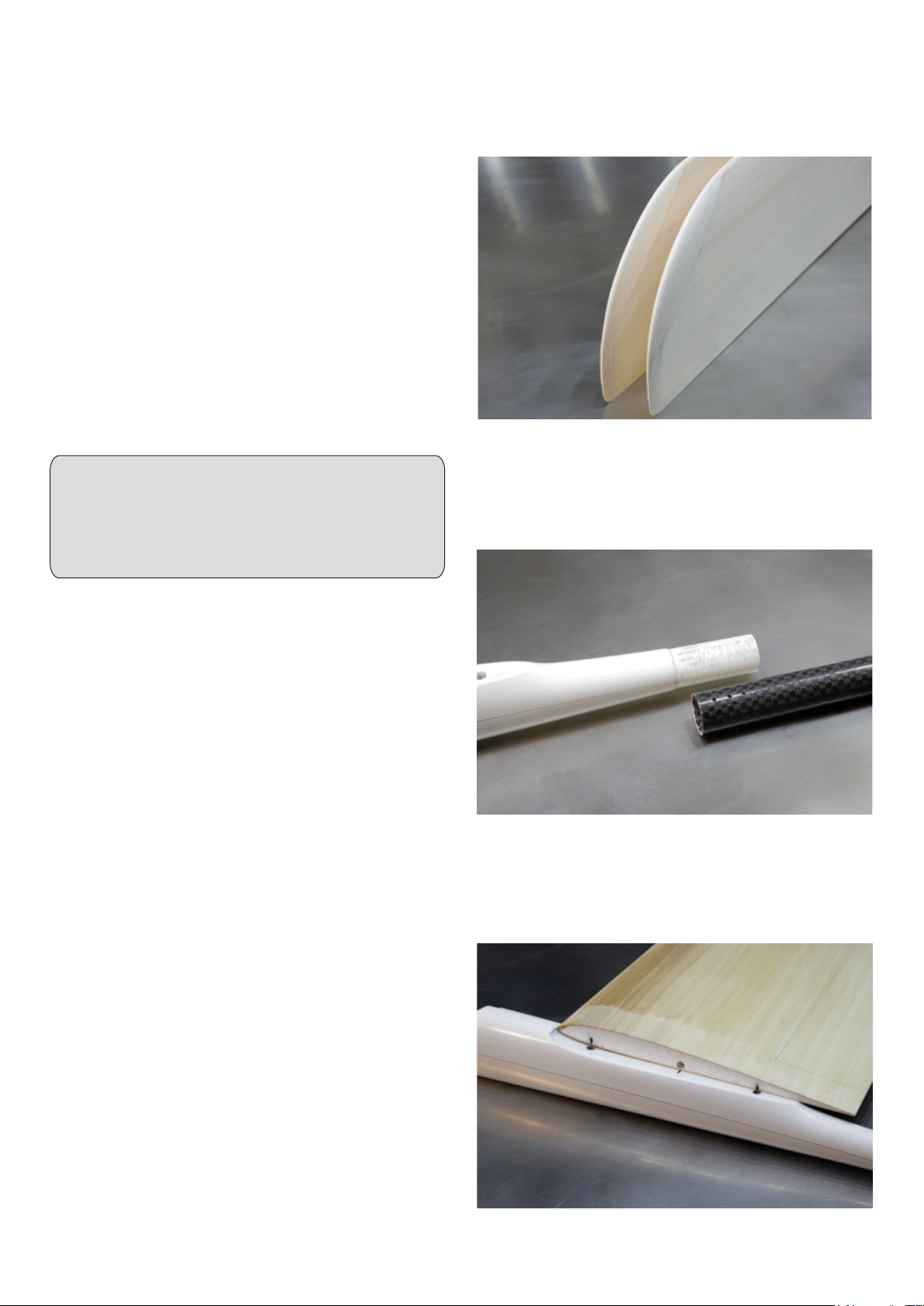
Joining Wing Panels
To achieve a proper dihedral angle the root of each wing
halve is sanded at a slight angle to fit.
1. Place one of the wing halves root on the pod saddle. Mark the
bottom side root of the wing 40mm and 120mm back from the
leading edge. Also mark the position of the wing servo wire
canals on the bottom side of the wing panels roots . Photo 3
P. 3
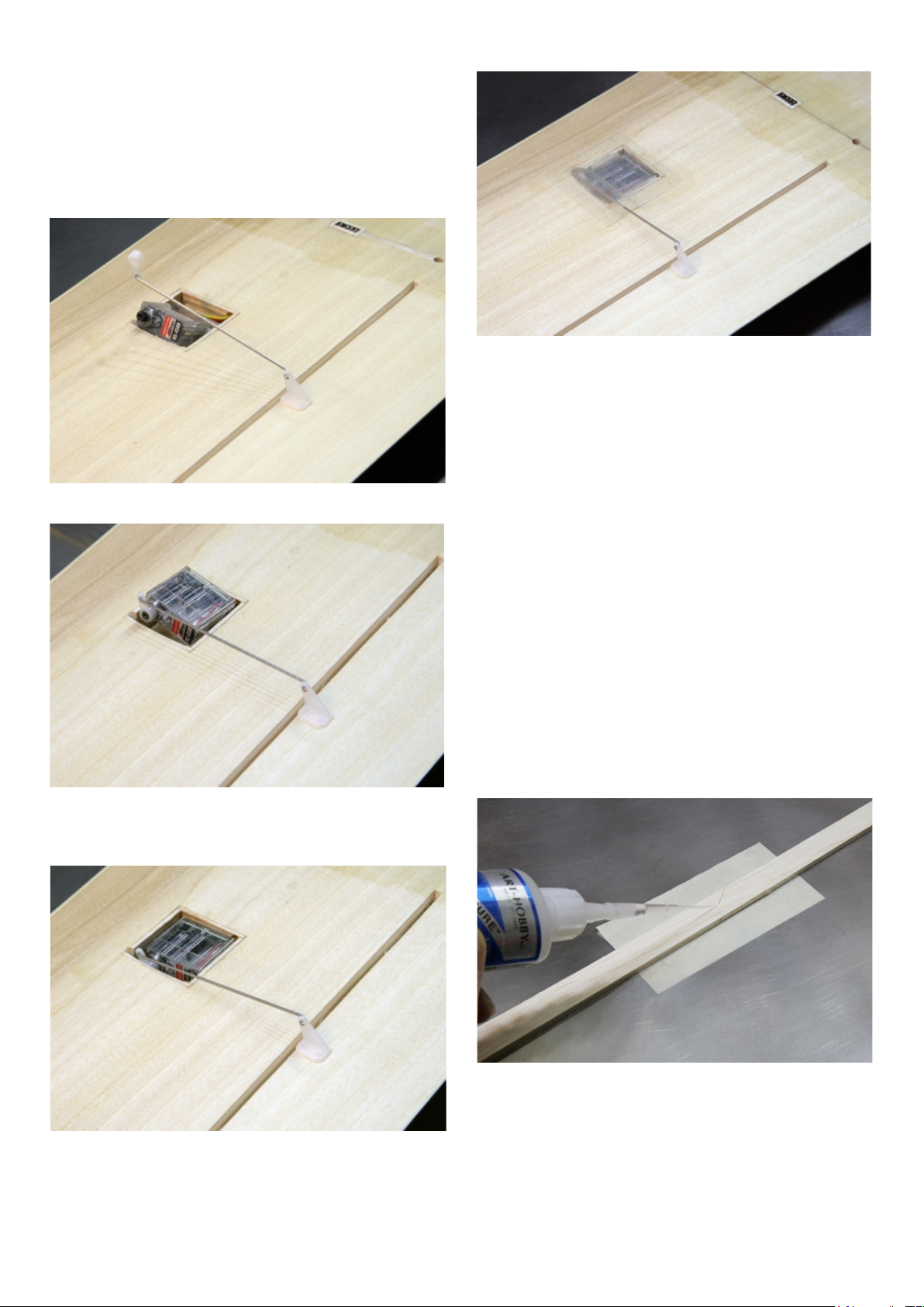
Pod and Boom Preparation
1. Use coares sand paper and rough up paint surface on the
fuselage pod joiner tip joiner tip. Trial fit the boom with the pod
and check the alignment.
2. Drill three 2mm holes in the boom, they will be used later for
gluing pod and boom together. Photo 2
Note: Do NOT glue together pod to boom in this stage.
P. 2
Momentum-DL v.1
Notes about the finished surfaces:
The fuselage is painted (in the mold). The white paint will be
damaged by thinners. The wood surfaces can be finished with
a proper clear finish. Remember that the wing has a foam
core and some paints may attack the foam internally.

5. Use hobby knife with sharp blade #11 and cut out cavities for
the blocks in both wing roots.
6. Shape the blocks before installation and test fit.
Use sandpaper and/or a knife and/or a rotary tool to completely fit
the blocks (loosely fit) to the wing’s contour.
7. Trial fit the blocks once again - adjust if necessary. Photo 6
4.Transfer markings to the other panel wing root. Photo 5
2. Find the two hardwood blocks. Place the blocks under wing
root, center each block under marks you made.
3. Mark the block width on the wing root foam and draw the wing
contour line on the block. Photo 4
The blocks will be hard points for the wing mounting screws.
9. Lay one wing half flat on the table.
10. Glue both blocks in place and wing halves together using 5
minute epoxy or 15 min. epoxy if you wish. Hold down both wing
halves together at the roots. Make sure that both wing panels
are aligned perfectly then raise wing tip 80 mm from the table
surface.
11. Wipe away all excess epoxy. Allow the epoxy to cure (at
least 30 minutes) then remove the masking tape.
12. Cut two strips 30mm wide and two strips 40mm wide from
glass cloth (supplied in the kit).
The cloth will reinforce the wing, top and bottom, around
the wing joint at the root. Photo 8
P. 4
8. Use hobby knife with sharp blade #11 and cut out a narrow
groove in the foam under wing skin around both wing roots.
Photo 7
When two middle segments are joined-glued together the
groove will be filled up with epoxy creating a stronger center
joint.
13. To keep the resin from spreading too far, apply masking tape
to the wing ~ 3mm away from the cloth’s edge. PHOTO 9
14. Mix a moderate portion of 20min. epoxy and using a small
brush or spreader stick apply epoxy to the top of the joint.
15. Lay prepared strips of glass cloth over the joint.
First lay the 30mm wide strip, then 40mm wide strip lay over.
Photo 9
P. 7
First layer
Second layer
P. 5
P. 6
P. 9
30 30 40 40
P. 8
Momentum-DL v.1 3

Dabbing will allow the epoxy to completely saturate the cloth and
adhere to the wood wing surface, it will also remove excess epoxy
and smooth the joint.(change new piece of the towel if needed)
17. Repeat steps 13-16 and apply reinforcing cloth to the bottom
of the joint.
18. Once the epoxy has set, remove the masking tape. Apply
fresh masking tape 2mm past the end of epoxy.
19. Use 400 grit sand paper and sand the joint smooth if needed.
DO NOT sand away the wing sheeting where the glass ends.
This will weaken the wing and could cause failure.
16. Use a small piece of paper towel, fold a few times together and
dab the gloss cloth. Photo 10
P. 10
Wing Servo Bays
Refer to glider drawing and check the servo bay markings
location on each wing. The servo bays need to be cut in size
to accommodate servo size you will be using.
(We recommend to use Hitec servos HS-45HB) Or you can
use other thin servos of your choice.
1. Using Hobby knife with blade #11 and flexible metal ruler as a
guide cut marked servo bays (in the bottom of the wing). Photo 11
2. Use small flat blade screwdriver to peel off cut out veneer.
Photo 12
3. Using new sharp blade cut foam around servo bay openings
then using small flat blade screwdriver remove foam from the bays
and with extra caution using very light pressure scrape clean
bottom of each bay. Photo 13
4. Cut eight 18mm wide strips from balsa board included in the
glider kit , then use the strips to make servo boxes that will fit into
servo bays. Photo 14
5.From included fiberglass cut four small rectangular pieces to
fit into bottoms inside servo bays. Photo 14
6. Test fit boxes into servo bays and mark on the box wall
locations of the servo wire canals. The boxes should be slightly
taller-projecting above wing surface).
7. Remove boxes then in marked position cut small round
opening for the servo wires.
8. Mask wing surface around the edge of each servo bays then
using 5 min. epoxy glue servo boxes into servo bays and using
20min. epoxy laminate bottoms of each servo bay with
prepared fiberglass cloth. Photo 15
P. 12
P. 13
P. 14
P. 15
P. 11
Momentum-DL v.1
4

Recommended tools for cutting ailerons:
- Two pins. will be used to project aileron inner corners/outlines
to the wing bottom sheeting. Photo 17, 18 & 19
- Triangle shaped Needle File (diamond) for finishing surfaces
after cuts. Photo 17
- Hobby knife with blade #11. Phot 17
(blade tip sanded round ~1mm radius and dull will be used to
make long cuts (top and bottom) over the aileron hinge.
Rounded tip blade will cut veneer and balsa strip molded inside
the wing but will prevent from cutting embedded hinge tape
- Balsa saw #A0530 (or saw blade #A0539) for making short
precision cuts on both sides of the ailerons cutting top and bottom
veneer sheeting. Photo 20 & 21
9. After epoxy cures remove masking tape.
10. Using sanding block with 320 - 400 grid sand paper sand
both servo boxes flush with the wing surface. Photo 16
P. 16
1. Use pins to project aileron inner corners/outlines to the wing
bottom sheeting. Photo 18
2. Place wing panel bottom side Up and draw a line connecting
both pins. Photo 19
P. 17
3. Remove pins and using balsa saw make short precision cuts on
both sides of the ailerons cutting top and bottom veneer sheeting.
Photo 20 & 21
P. 18
P. 19
P. 20
P. 21
Wing Control Surfaces
Refer to glider drawing and check ailerons and flaps pencil
marked on the wing. There is a thin ARAMID hinge tape molded
under wing upper skins where the aileron are. Fig.1
Fig. 1
Momentum-DL v.1 5
Aramid hinge for the ailerons is
laminated under bottom wing skin
Balsa strip inside wing

P. 24
9. Using rounded tip blade make deep angle cut to embedded
hinge tape. Photo 25
10. Remove cutout (wedge shape material) then take the triangle
shaped needle file and using pull motion smooth the edges inside.
cut. Photo 24
P. 25
P. 23
P. 22
6. Place wing Top side UP. Use metal ruler as a guide and hobby
knife with sharp #11 blade. First make few straight light strokes
cutting the Top veneer sheeting only.
7. Next using rounded tip blade make straight deep cut into
embedded on the bottom hinge tape. As soon as the knife tip
reaches the tape it will start sliding over. Photo 22
8. Now position metal ruler 3mm from the first cut (in direction of
trailing edge) and using fresh sharp blade #11 make second
straight cut to the bottom hinge. Photo 24
The wedge shape gap made over hinge in the aileron top side
allows aileron to deflect UP. Photo 27
Small groove in the bottom veneer sheeting over the hinge line will
allow aileron to deflect steep angle DOWN. Photo 28
P. 27
P. 28
Momentum-DL v.1
6
4. Place wing bottom side UP. Using metal ruler as a guide and
hobby knife with rounded tip blade #11make few straight light
strokes cutting bottom veneer sheeting. As soon as the knife tip
reaches tape under veneer will start sliding over. Photo 22
5. Using triangle shaped needle file to clean the groove slightly
making it wider. Photo 23
P. 26

Wing Servo Installation and Wiring
We recommend HS-45HB Hitec servos to be used for the ailerons
1. Connect each of the aileron servos to the receiver.
2. Turn ON the radio and center servos, use the servo reversing
in the transmitter if the servo moves in the wrong direction.
3. In preparation to install aileron servos first remove control
horns from both servos and cut off mounting tabs. Photo 29
4. Cut off plug connectors from servo wires.
5. In bottom of wing center joint cut small rectangular opening to
accommodate 4-pin connector. Photo 30
P. 29
6. Run servo wire through the wing panel (Push-rod tube can be
used to help pull the wire through). Photo 30 & 31
11. Holding connector face down solder both servo wires to the
connector. Be very careful to keep the polarity correct. Photo 35
P. 30
P. 31
7. Position servo properly in their bays and pull both servo wires
from the center opening to eliminate any slack. Photo 32
8. Cut both wires approximately15mm from the wing and using
masking tape mask wing around center opening Photo 33
9. Lift up servo in their bays and pull servo wires from center
opening will be easier soldering wires to the plug with extra wire
slack. Photo 34
P. 32
P. 33
P. 34
10. Take the 4-pin female connector and cut short soldering pins.
With shorter pins it will be easier gluing it into the wing. Photo 34
P. 35
Momentum-DL v.1 7

12. Rotate plug face UP then use CA and glue thin planks to the
connector walls - boxing it around. Photo 36
P. 36
13. Now pulling gently both servo wires and push boxed connector
into center opening. If satisfied with fitment mix small amount of 5
min. epoxy and glue connector flush into joint. Photo 37
14. Use two 12” servo extensions and 4-pin male connector for
making plug type wing to receiver wiring harness. Photo 37
P. 37
15. Wires and 4-pin male connector with shortened soldering pins
prepared for soldering Photo 38.
16. Solder wires to 4-pin male connector in exactly same order
and polarity as you solder servo wires to 4-pin female connector
glued into wing center joint.
During soldering align wires long ways to make nice slim
connector plug.
After soldering wires wrap plug and wires with sewing threads
securing it with CA - this will make strong plug connector that
could be plugged and unplugged from wing hundreds of times with
out damaging. Photo 39 & 40
P. 38
P. 39
17. Now plug harness to the wing and connect to corresponding
aileron channels in the receiver. Turn ON the radio then power
receiver - test servos proper movement, direction and set them to
neutral position. Photo 41
P. 40
P. 41
Aileron Servo and Control Horn Installation
Note: Aileron control horns are installed on the aileron
bottom surface with the horn posts projecting from top
surface of the aileron.
1. Check aileron servo for proper positioning in servo bays.
2. Use angle ruler and position it perpendicular to the aileron
trailing edge pressing ruler edge to the servo horn. If satisfied with
alignment draw light pencil line on the aileron surface. Photo 42
Momentum-DL v.1
8

9
5.Cut small opening between posts projecting from top aileron
surface (close to the back post) and remove all material until you
see bottom veneer inside opening. Photo 44
Note: The opening need to be small enough to be completely
covered by horn back plate after is installed.
3. Take horns back plate and place on aileron surface centering
on the pencil line with front of the plate being flush with front edge
of the aileron. Now using pencil make mark on veneer center of
each plate hole.
4. Drill holes in marked position then insert control horn posts into
holes and using ruler check alignment. Photo 43
P. 44
9. Using soldering iron (set to low heat) melt projecting post flat
with the plate surface. Photo 47
6. Mix small portion of 5 min. epoxy and using toothpick fill
opening with epoxy.
7. Secure horn with back plate pushed over the posts. Wipe out
any epoxy that may have gotten squeezed out from under back
plate. Photo 45
8. After control horns and their back plates are secured the nylon
posts should be trimmed so they project out 1mm above back
plate. Photo 46
P. 42
P. 43
P. 46
P. 45
10.Using small flat fine file or fine sanding paper wrapped around
spreader stick sand melted surface smooth. Photo 48
P. 47
P. 48
Momentum-DL v.1

14. Next mount servo arm on the servo shafts and secure with
screw. Photo 50
16. To improve aerodynamics and esthetic look of the glider we
recommend covering aileron servos with Art Hobby’s universal
wing servo covers (#A0031). Photo 52
11. Place the servos in the center of servo bays, lock the ailerons
in a neutral position securing both ends of each control surface to
the wing’s trailing edge with a piece of tape.
12. Now measure distances between servos control arms and
aileron control horns, according to these measurements make
two short push-rods from the supplied wires.
We suggest making “Z” bend on both ends. Photo 49
13. First connect push-rod to the aileron horn, then to the servo
arm. Photo 49
15. Now position servo in it’s bay immobilizing it in place with
balsa shims made from balsa board and pushed between servo
and front and back wall of the servo bay securing all with small
amount of silicone sealer. Photo 51
P. 49
P. 52
P. 50
P. 51
Wing Mounting
1. Place the wing on the fuselage wing saddle, then use a sharp
pointed pencil to mark the wing’s trailing edge on the fuselage.
2. Remove the wing, then measure the distance between the
marked line and the center of the two threaded holes in the wing
saddle.
3. Place the wing upside down and transfer both measured
distances onto the bottom center of the wing joint, they should
match previously made markings.
4. Using 4mm drill bit and drill from bottom side two holes in the
marked position.
Remember that the hole has to be drilled at an angle to match
the angle of the wing bolt screwed into the fuselage.
5. Find two M4 wing screws and screw them into the wing saddle
to check the angle, then from the top side of the wing open the
holes properly to fit the wing screws.
Push-rod Installation
Best method to install push-rod tubes inside tail boom is
attaching them to wedge shape push-rod installation balsa
board (included in the kit) board will fit inside the boom’s entire
length. After inserting board with tubes into boom friction
will hold it in place.
Balsa board is too long to fit inside glider box so was specially cut
in two pieces and packed together with glider wing in the box.
1.Use thin CA adhesive glue both board pieces together. Photo 53
2. Place push-rod tubes on the board spaced ~2mm apart
at the back end of the board with one tube projecting ~60mm from
back of the board and other tube projecting ~140 and tack them
with few drops of CA. Photo 54
Gradually spread tubes apart moving forward to wider end of
the board gluing them to the board with CA adhesive.
As final step use sewing thread and wrap board with tubes
securing them together and making few extra windings on both
ends of the board. PHOTO 54 & 55
P. 53
Momentum-DL v.1
10

11
5. Trial fit the plate to the boom and using masking tape mark
position of the mount front end 120 mm from the boom end. Also
drill 2mm hole 25 mm from masking tape edge. Photo 60
2. Drill two 2mm holes in mount saddle. Next using drill and
needle files make narrow 2 mm wide vertical opening in mounts
vertical trailing edge. Photo 57
Tail Installation
Horizontal stabilizer is removable and is attached to
carbon composite mount with two M2 and nylon retainers.
1. Locate all tail components. Photo 56
3. The bottom part of the carbon mount has a round shape to fit the
boom. To insure a perfect fit to the boom wrap the tail part of the
boom with 320-400 grid sandpaper then place mount on the paper
and pressing it gently down make a few strokes back and forth.
Photo 58
PHOTO 56
P. 56
P. 57
120 mm
~25
P. 58
4. Place mount bottom side UP and using 5 min. epoxy glue brass
threaded retainers, you can screw M2 tail screws into brass
retainer to hold brass retainers in proper position and aligned.
Photo 59
6. Use round needle file to enlarge drilled hole in the boom. The
hole needs to be enlarged at a steep angle and size to
accommodate elevator push-rod tube. Easiest method to enlarge
hole with steep angle is to mount file in small electric drill and with
file rotating slowly lean drill in booms tail end direction. During
filing try fitting push-rod tube a few times until it fits snuggly into
opening and flat as possible.
P. 59
P. 60
P. 54
P. 55
Momentum-DL v.1

7. When satisfied with fitment insert push-rod wire into opening
pushing it forward until wire comes out from the front end of the
boom. Wire will be used to guide elevator push-rod tube to its
opening in the back of the boom. Photo 63
P. 61
P. 62
P. 63
P. 64
P. 65
P. 66
8. Now take the board with push-rod tubes and insert longer tube
into boom and slide shorter tube over projecting push-rod wire.
Photo 64
9. Push board with tubes into boom until stops and elevator tube
comes out from its opening and rudder tube from the boom end.
Photo 65
10. Pressing elevator tube to the boom wall use thin CA adhesive
and glue tube into its opening in the boom . Photo 66
11. After CA sets pull out elevator push-rod wire from tube then
using hobby knife trim elevator tube 1-2 mm above boom surface
and put temporarily aside. Photo 67
12.Take horizontal stabilizer mount and from inside screw M2
mounting screw until they project from top of the mount saddle.
Position mount on the stabilizer center line and using projecting
screw mark to points in the line for drilling. Photo 68
13. Use 3mm drill and drill two holes to fit nylon retainers .
(Be sure that holes in the stabilizer are matching holes in the
mount. Fit into holes nylon retainers and check if they are flush
with stabilizer bottom surface (nylon retainers are slightly longer
so they need to be sanded to fit flush) Photo 69
P. 67
Momentum-DL v.1
12

13
P. 68
P. 69
14. If satisfied with fitment glue retainers in place using a few
droplets of thin CA adhesive. Photo 70
15. In preparation to install elevator control horn use M2 screws
and attach stabilizer mount to the horizontal stabilizer then
place it upside down. Photo 71
16. Mark position and install elevator horn in the center behind
elevator mount. When elevator moves down horn should freely
retract into narrow slot in back of the mount. Photo 72 & 73
P. 70
P. 71
P. 72
P. 73
17. If all operates correctly, secure horn in place with back plate
and 1-2 droplet of thin CA adhesive (#A0106). Photo 74
18. Trim off posts projection from the horn back plate. Photo 75
P. 74
P. 75
Momentum-DL v.1

14
20. Hold boom with elevator tube pointing UP then positioning
stabilizer mount on the top with front of the mount aligned with
masking tape edge then us pencil and outline its position.
Photo 77
21. Put mount temporarily aside and clean the marked surface of
the boom with sand paper. Then position mount on the boom and
glue it in place with a few droplets of thin CA adhesive ( #A0106) .
Fine applicator tips (#A0303) are recommended for this operation
tip will help applying CA very precisely. Photo 78
19. Using soldering iron (set to low heat) melt projecting post flat
with the plate surface and sand melted surface smooth.
Photo 76
P. 76
22. Now take the vertical stabilizer and using hobby knife with
sharp blade cut slot in marked position to accept the boom.
Photo 79
After cutting check stabilizer fitment on the boom (should fit
snug). If satisfied remove it and put aside for a moment.
23. Mount horizontal stabilizer then place vertical stabilizer
back on the boom, centering on the boom aligning it
perpendicular to the horizontal stabilizer. Photo 80
25. From supplied fiberglass cloth cut two rectangular pieces
25mm x 45mm, they will be used to secure permanently vertical
stabilizer to the boom. Photo 82
24. Holding in position secure vertical stabilizer to the boom
with a few droplets of thin CA adhesive. Photo 81
P. 79
P. 80
P. 81
P. 82
P. 77
P. 78
Momentum-DL v.1

15
26. Mix a small portion of 20min. epoxy and using a small brush
apply epoxy to one side of boom and to the vertical stabilizer
surface 20mm around the boom.
27. Lay prepared patch of glass cloth centered on the boom and
press it to the stabilizer surface covered with epoxy.
28. Use a small piece of paper towel, fold a few times together and
dab the glass cloth.
29. Repeat steps 26 - 28 applying glass patch to other side of the
stabilizer and boom joint and put aside for epoxy to set. Photo 83
P. 83
Pod Preparation
1. Cut openings in the wing saddle. Photo 84
Tail Boom and Tail Servo Installation
1. Remove push-rod wires and insert them into the holes in the
back wall under canopy until they project from tip of the pod.
Photo 85
3. Push boom with push-rod tubes into pod guiding tubes into
holes and pushing them through until boom is fully connected
with pod. Then pull wires out from tubes. Photo 87
2.Take tail boom with projecting push-rod tubes push them over
the wires projecting from pod connecting tip. Photo 86
P. 85
P. 86
4. Align both tubes horizontally parallel to each other and
secure in this position with 1-2 droplets of CA adhesive. Next
use hobby knife to cut both tubes approx. 15mm from the wall.
5. Insert rudder push-rod wires into their tube.
6. Take rudder horn and mark horn position on the rudder
aligning it with rudder push-rod wire then drill two holes for the
horn posts. Make small “L” bend on the wire end, connect horn
and push horn posts to rudder drilled holes. Photo 88 & 89
P. 87
P. 88
P. 89
Momentum-DL v.1
60 mm
25
P. 84

11. Take “Z” bended push-rod wire and insert into elevator
tube through the opening in back of the stabilizer mount.
12. Connect “Z” bend wire to elevator control horn then using
M2 screws attach horizontal stabilizer to the mount. Photo 92
P. 91
P. 92
7. Secure horn with back plate pushed over the posts. and secure
in place with 1-2 droplets of thin CA adhesive.
8. After control horn and back plate is secured the nylon posts
should be trimmed to project 1mm above back plate.
9. Now using soldering iron (set to low heat) melt projecting post
flat with the plate surface. Photo 90
10.Using small flat fine file or find sanding paper wrapped around
spreader stick sand melted surface smooth. Photo 91
13. Mount wing to the pod.
14. Holding wing horizontally and look from the nose side on the
horizontal stabilizer then carefully rotating boom align stabilizer
parallel to the wing trailing edge.
15. When satisfied with alignment remove wing very carefully.
Turn pod with boom assembly bottom side up and holding
horizontally apply slowly 3-4 drops of thin CA adhesive into
gluing holes drilled earlier in the bottom boom. Photo 93
P. 90
P. 93
16. Locate servo tray supplied with the glider in accessory bag.
17. Using 5 min. epoxy glue to under side of opening in the
pod in front and back of servo opening. Photo 94
18. Prepare each servo by trimming half of one mounting tab.
Photo 95
19. Mount servos on tray with servo screws.
20. Connect servos to the receiver turn ON transmitter next
power receiver and using transmitter set both servos to neutral
position. Attach servo horn to one servo and select arm pointing
90 degrees out then cut off any unused arms. Repeat control
horn arm selection on second servo. Attach arms to te servos
each pointing out sideways. Photo 96
21. Using masking tape immobilize elevator and rudder in
neutral positions.
22. Position wires over servo arms and mark both wires for “Z”
bends.
Using flat nose pliers make “Z” bends (cut any excess wire).
23. Remove servo arms from servos and connect to “Z” bends
then attach servo arms back to the servos and check alignment.
PHOTO 96
Momentum-DL v.1
16

24. Finalize all radio gear installation. Photo 97 & 98
Attaching Canopy
We recommend attaching canopy with two pieces of clear
scotch tape adhered to both sides of canopy. To access the
interior, simply peel off tape on one side (other side will act as a
hinge). This is good for opening the canopy a few times, then
tape has to be replaced. This is a simple and very dependable
method. There is no danger for the canopy to be blown off
during flight- because canopies of all our gliders are perfectly
fitted to their fuselage pods.
Servo
(-) wire to servo
(signal wire to servo
4-pin female connector 4
4-pin male connector
3-pin female servo connectors - (cut out servo leads or 12” servo extensions)
Flaperon
4-Pin connectors (1-pair) #A1304
Servo
(+) wire to servo
P. 96
25. Before flight, double check balance and control throw direction
for free and proper movement.
Balancing and Control Throws
1. Before flight, check direction of motor rotation.
2. Double check balance and control throw direction for free and
proper movement.
3. Try some hand launches and straight glides over a grass field
before high launching the glider. This will be a good time to adjust
control throws and final balance.
STARTING CONTROL THROWS:
Flaperons: 15mm UP, 9mm DOWN (dual rate 55%)
Flaperon brake: 45+ deg. DOWN
Elevator : 10mm in each direction
Rudder: 25 -30 mm in each direction
BALANCE POINT (C.G.):
The completely assembled glider must balance level when raised
at the marked ”C.G” point under the wing roots, a tolerance of
5mm back and forward of marked position is permissible.
Balance the Momentum ~60 mm back from the leading edge of the
wing at the center section of the wing.
NOTE:
Control throws and glider C.G. are quite subjective according to
the flying conditions and pilot’s preferences. These throws are
simply a starting point. Experimentation is recommended to
achieve a smooth flying plane you are comfortable flying.
P. 97
P. 98
Momentum-DL v.1 17
This manual suits for next models
1
Table of contents
Other Art Hobby Toy manuals
Popular Toy manuals by other brands

Flowtoys
Flowtoys FLOWLIGHT-FS Optimization guide

ROBBE
ROBBE Crazy Boy Assembly and operating instructions

Kogan
Kogan KIDS 45-PIECE TACTICAL VEST KIT user guide

Claessens' Kids
Claessens' Kids KID’Sleep My Dream quick start guide

Power Wheels
Power Wheels MONSTER TRACTION K8285 Owner's manual & assembly instructions

LGB
LGB 70305 manual