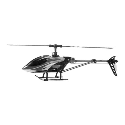
Art-Tech Falcon Beginner User manual

size:210x285mm
WWW.ART-TECH.CN
WILLING:SERVE ALL THE MODEL HOBBYISTWILLING:SERVE ALL THE MODEL HOBBYIST
OPERATING MANUAL
OPERATING MANUAL
Falcon Beginner
Falcon Beginner

CATALOG
★SPECIFICATIONS 03
★CAUTION
★TIPS FOR SAFETY
04
05
★PARTS LIST 08
★FUNCTIONS FOR CONTROL SET 09
★BALANCING THE MAIN ROTOR BLADES AND TAIL BLADES
22
★COMMON FLIGHT
13
12
14
★NORMAL FLIGHT
16
★INSTALLATION
★MAINTENANCE
10
11
★CHARGE MODE AND WARNING 06
★SAFETY INSTRUCTION OF LI-POLY BATTERIES 07
★ALL SPARE PARTS AND EQUIPMENT
19
★PREFLIGHT CHECKLIST
25
★PARTS REPLACING
★SPARE PARTS LIST

SPECIFICATIONS:
※Specifications may change without notice, please refer to the real one for configuration. 2011.02
※This picture only for reference.
CONFIGURATION
100%
★★★☆☆
★★★☆☆
★★☆☆☆
★☆☆☆☆
PRODUCT CHARACTER
Accomplishment
Difficulty of assembly
Difficulty of maintain
Difficulty of control
Anti-shatter
www.art-tech.cn 3
★ mm
★ width:110mm
★ Height:230mm
★ Main rotor diameter:545mm
★ Tail rotor diameter:149mm
★ Weight:479g(without battery)
Length:610
★ Flying Weight:587g
RC System:EFLY-6BII 2.4GHz
★ Servo:9gx4
★ ESC:20A/brush
★ Motor:380
★ Battery:11.1V,1300mAh(Li-Po)
★ Gyro:V3
★
Himag brushed motor
Thank you for choosing the Falcon beginner model helicopter from Art-Tech. This
helicopter is powered by a micro electric motor and is our latest product. The Falcon is equipped with
adjustable collective pitch, which makes it suitable for outdoor flying.
Falcon beginner helicopter is designed with Bell-Hiller collective pitch system. With the good
combination of stability and flexibility as well as anti-strong wind ability, it is suitable for both outdoor
and indoor flying. Equipped with head-lock gyro, it is with excellent stability. It has perfect flying ability
due to specifications of powerful Himag brushed motor, li-poly battery.
Falcon 400 training helicopter is made of high-dense plastic and it is able to withstand the minor
crashes to reduce the flying cost, which makes your flying more joyful.

CAUTION
NOTE
TIPS FOR SAFETY
R/C modeling is a hobby with high technology and should not be considered a children's toy. There is
risk involved during the operation of this product and the user should take all precautions seriously or
serious bodily injury may result.
I mp r op er di sa s se m b l y, i mp ro p er a d ju s tm en t s a nd s e tu p c an le ad to u n sa t is fa c to ry or u n sa f e
operation. If you have any questions regarding the use, maintenance, or safe operation of this model,
please contact your local retailer.
As with any R/C product there are risks involved when flying this model. A beginner should seek the
help of a qualified skilled R/C pilot to ensure that the model is airworthy and capable of safe operation.
Any damage, neglect, or unfamiliar use of this product can cause unexpected accidents or injury. Be
sure to read this manual and follow all of the safety notes. Remember this is not a toy and children should
be supervised prior to starting or flying this helicopter.
1. Locate an appropriate location to fly your helicopter:
R/C he l ico p ters ar e c a pab l e o f fl y ing at hig h s p eed s , t h us p osi n g a cer t ain de g ree of p ote n tia l
danger to both the flyer and bystanders. Try to choose and appropriate flying site where the surface is
flat, smooth, and clear of obstacles. A good choice would be and empty parking lot free from parked cars
and pedestrians. An empty gymnasium or warehouse without obstructions. Do not fly near buildings,
trees or high voltage lines to ensure the safety of yourself and others and your model. Do not fly your
helicopter during inclement weather such as rain, snow, high winds or darkness.
www.art-tech.cn
4

Pri o r to turni n g o n your model and trans m itter check to make
sure that no one e l se is operating on the same f r e q uency a s yo ur
model. Frequency i n t e r f e r e n c e can cause y o u r model to b e c om e
u n c o n t r o l l a b l e a s w e l l a s o t h e r m o d e l s i f t h e y a r e o n t h e s a m e
frequency. The help of and experienced pilot will ensure that you will
have a well t r immed, c o r rectly f u n ctioning h elicopter for th e first
flight. Included with this helicopter is a model flight simulator better
known as FMS. It is stron gly advised tha t y ou first practice on the
simulator prior to making a flight with your new helicopter. Practice
o n t h e s i m u l a t o r w i l l g o a l o n g w a y i n p r e v e n t i n g a c r a s h i n t h e
beginning.
2.Obtain the assistance of and experienced pilot.
4.Always be aware of the rotating blades.
During the o p eration of y o u r new F alcon h elicopt e r the m ain
r o t o r a n d t a i l r o t o r w i l l b e s p i n n i n g a t a h i gh r a t e of s p e e d . Th e
blades are capable of inflicting serious bodily injury and damage to
you and t o others. Be c o n s c i o u s of your a c t i o ns and be careful to
k e e p y o u r h a n d s , f a c e, e y es , a n d l o o s e c l o t h i ng a w ay f r om t h e
b l a d e s a n d g e a r s . A l w a y s f l y y o u r m o d e l a s a f e d i s t a n c e fr o m
yourself and others as well as nearby objects. Never take your eyes
off the model or leave it unattended while it is turned on. Always turn
off your model, then your transmitter after each flight.
5.Keep your Falcon helicopter away from heat and
humidity.
Your new Falcon helicopter is a hi-tech electronic device; never
su bj e c t y o u r m o d e l t o te m p e r a t u r e e x t r e m e s, d o n o t l e a v e y o u r
m o d e l i n a n a u t o m o b i l e f o r e x t e n d e d t i m e s b e c a u s e h i g h
temperatures can damage the delicate electronic and plastic parts.
TIPS FOR SAFETY
3.Same frequency around is forbidden.
Please check that no one else is using the same Transmitter
channel at the same time, this will lead to a loss of control of the
airplane and a crash.
Novice
Novice Expert
www.art-tech.cn 5

www.art-tech.cn
6
Operating
CHARGING METHOD AND CAUTIONS
Specifications:
Input voltage: DC 10V~15V
Output voltage: DC 7.4V & 11.1V (to 2 or 3 cell Li-Po battery)
Charging current: 0.3A~1.0A (can be continuously adjusted)
Indicator state:
Green: Charge complete & no battery
Red: Charging
Flash: Drip current charging
The batteries are inspected separately. When the voltage
reaches 4.20V, the charging process stops.
LI-Po batter y(balance changer)
ATI-0910 LI-Po batter y(balance changer) specifications
12V DC Power supplier
Then plug cigarette into its socket in car (Adapter should be
connected if charge at home: connect the adapter to home
power socket, then plug the adapter' DC end to charger).
The LED will turn green indicating it is ready for charging.
2. Connect the battery to charger per its interface mark. The LED
becomes red, which means charging is on the way.
3. Adjust the current among 0.3A~1.0A. In order to prolong
battery' life-span, we recommend to charge them u nder low
current if you have enough time.
4. When LED flashing, the charger will enter the stage of drip
current charging. The LED turns green when fully
charged , and the battery will be used at any time.
1.
Notice
1. Do not insert anything conductive into the cooling hole when power is on, or damage will be caused to
the charger.
2. While charging is in process, please do not make it near flammable materials.
3. It is not allowed to charge two-cell and three-cell Li poly battery at the same time.
4.Expect Li poly battery, this charger is not allowed for other kinds of battery.
5. While charging, please keep it out of the reach of Children.
6. When this charger is in use, please do not go away and leave it unwatched, if any abnormality occurs
(such as the power indicator is off, the temperature of the battery rise rapidly, etc.) stop charging
immediately.
7. Please do not use power with output voltage higher than 15V.
8. Please do not disassemble the charger or its accessories.
9. When the battery is not cool down, please do not urge to charge it.

www.art-tech.cn 7
1. Do not disassemble or reconstruct the battery.
2. Do not short-circuit the battery.
3. Do not use or leave the battery nearby the fire, stove or heated place (more than 80℃).
4. Do not immerse the battery in water or sea water, do not get it wet.
5. Do not charge the battery under the blazing sunlight.
6. Do not drive a nail into the battery, strike it by hammer or tread it.
7. Do not impact or toss the battery.
8. Do not use the battery with conspicuous damage or deformation
9. Do not charge a warm battery. Allow it to cool completely before attempting to charge.
10. Do not reverse charge or over discharge the battery.
11. Do not connect the battery to the ordinary charger socket or car cigarette jack.
12. Do not use the battery for unspecified equipment.
13. Do not touch the leaking battery directly, please wash your skin or clothes with
water if they are bedewed by liquid leaking from the battery.
14. Do not mix the Li-Poly battery with other un-chargeable battery in using.
15. Do not continue charging the battery over the prescribed time.
16. Do not put the battery into the microwave oven or high-pressure container.
17. Do not use the abnormal battery.
18. Do not use or keep the battery under the sunlight.
19. Do not use the battery nearby the place where generates static electricity (over 64V).
20. Do not charge the battery when the environmental temperature is under 0℃ or over 45℃.
21. If you find the battery leaking, smelling or abnormal, stop using it and return it to the seller.
22. When the battery is charging, please do not make it near the flammable materials!
23. Keep the battery away from the children.
24. Use the specified charger and observe charging requirement (under 1A).
25. When using by minors, parents should show them to the correct instruction.
SAFETY INSTRUCTION OF LI-PO/NI-MH BATTERY
Notice
1.Be fully charged under no more than 1 A voltage by using the specified charger.
2.Be discharged under 10C voltage but avoiding discharge time too long to harm the battery.
3.Repeat the first and second step one or two times.
4.When the Li-poly battery was stored more than 3 months, it needs to be recharged to
maintain its voltage, and ensure its life time.
NOTIFICATION FOR ESC
1. The function of this ESC was in the best condition after factory setting; please do not
change it by yourself.
2. Before connecting the battery, please make sure the throttle and Micro-trim were in the
lowest position. If
the throttle and Micro-trim were not in the lowest position by mistake after connecting the
battery, you can
cut off the battery; move the throttle and pitch to the lowest position, then connect the
battery.
3. The ESC of the airplane was in a good cooling position after factory assembly; please do not
move its
position.
4. The ESC should be connected to the brushless motor correctly, otherwise the motor will be
reversed

Receiver
Ser vo
ESC( ) brushed
380 Himag brushed motor
Gyro
Batter y Charger
Training frame Transmitter
PARTS LIST
Airframe
※THIS PICTURE ONLY FOR REFERENCE.
The Fa l c o n incl u d e s the f o llowing p a rts, ple a s e chec k to ma k e sure t hat all of the beginner
parts are include d in y o u r kit. S hould a n y t hing be missing p lease c o n t act your local d e aler.
www.art-tech.cn
8

FUNCTIONS FOR CONTROL SET
PICTURE OF CONTROL SET CONNECTION
GYRO ADJUSTMENT
1. Connect to
tail servo
Elevator down
Rudder
left
Throttle Max
sweepback
adjustment trim switch
Dual Rate
(D/R) Switch
Charger port
Frequency Binding Switch
Servo reverse switch
Power switch
Power indicator
Hook
Handle
Antenna
Trim
Dual Rate(D/R)
Trim Switch
Rudder
right
Throttle up
Left
Aileron
Up
Right
Aileron
Up
RECEIVER
ER61-2.4GHz
CH
Flapron
Landing gear
Rudder
Throttle
Elevator
Aileron
Power/
Frequency bind
www.art-tech.cn 9
MODE 2
Throttle Min
.Gyro signal Co nnect to Ch 46
.Gyro gain Connect to Ch55
3 Connect to tail servo.
2 Gain adjustment.
1 Rudde r itinerar y adj ust ment .
4. Reverse switch for servo
Assembling Gyro :
Make sure radio control system and servos are in good working condition, and the servo arms are in right
position.
1.
2. Fix the gyro to the right place close to CG.

PREFLIGHT CHECKLIST
of the helicopter and cause a crash or serious personal injury.
10.After completing your flight disconnect the power from the battery in the helicopter first, then you
may turn off your transmitter. Never turn off the transmitter first since it could cause you to loose control
www.art-tech.cn
10
Suggestion: if there is no deflexion, it is better to increase the gain of gyro.
3.Plug the CH4 and CH5 signal connecters to the receivers respectively and connect the servo on the
tail pipe.
4. me.Switch the transmitter on and center the rudder joystick as well as the tiny mix. Connect the receiver
to the power and wait
5.Set the reverse switch on the gyro: Turn the helicopter head to the left, if the servo's movement on the tail
pipe the same as the servo's when turning rudder joystick right and that means the direction is ok. Or you
need to turn the reverse switch to the other end.
6.Gain adjustment: when testing the helicopter, to watch whether there is a deflexion. If it exists, and tail
wing turns right,you need to turn the gain switch right to increase the gain and vice versa.
The following actions should be perfor med by the operator prior to flight.ever y
1.Ensure that the blades have been balanced and are equally tight on the blade grips, Note: if you hold
the helicopter on its side the blades should be tight enough that they do not drop even if model is shaken.
2.Inspect the helicopter for any loose wiring, screws, fasteners, connectors, prior to flying.
3. Turn on your t ransmi tter firs t followe d by connecting the battery to the speed controller in the
helicopter, you should also ensure that the 3D switch is set to normal and the throttle is set to off, i.e.
all the way down.
4.Walk away from the helicopter with the antenna collapsed to check range, you should be able to walk
50 paces away and still have full control over the helicopter. If the distance is significantly less
check antenna wire and connections on the receiver of the helicopter.
5.Check the CG (center of gravity) by having the main blades at 12:00 o'clock and 6 o'clock. Lift the
helicopter by the fly bar and observe the landing skids. The skids should be level with the ground
and not leaning forward or backward. If they lean adjust the position of the battery by sliding it leans
it backwards or forwards until the skids remain level.
6.If this is your first flight, it is strongly recommended that you use the provided training gear before
attempting . the training gear w ill prevent a tip over which can cause blade to fly the model tipping, and
or main shaft damage. once you have your helicopter you can remove the training gear.learnt to hover
7.Fully extend the antenna prior to lift-off this will ensure you have maximum radio range.
8.Slowly apply throttle and observe the rotor disk, it should appear perfectly flat with no noticeable tilt or
lean. If the rotor seems tilted or is leaning move the trim levers on the transmitter until the rotor disk
appears flat.
9.After lift-off and holding the helicopter in a hover it should require very little input on the sticks to
maintain a stable hover. Should the helicopter wander forwards backwards or side to side, adjust the trim
levers on the transmitter until the hover is stable. Note: a well trimmed helicopter should be able to
hover for short periods with very little input from the pilot.

NORMAL FLIGHT
Char t for R/C mode 2(left hand throttle)
Up
Down
nose turn left
nose turn right
Nose down ahead
nose up back
Pull the left
stick downward
Pull the left
stick upward
Pull the left
stick left
Pull the left
stick right
Pull the right stick
downward
Pull the right
stick upward
Pull the right
stick left
Pull the right
stick right
model goes left
model goes right
www.art-tech.cn 11

ALL SPARE PARTS AND EQUIPMENT
www.art-tech.cn
12
Gyro
Tail Servo
Motor
Canopy
Battery
ESC

POWER CHECKING
mark for adjustment
mark for adjustmentmark for adjustment
BALANCING THE MAIN ROTOR BLADES AND TAIL BLADES
Check and correct the balance of the main rotor blades before your
first flight. Place a 3M screw through the two main blades as shown in
th e diagram. Tighten th e blades an d ensure that they are st raight as
shown in the diagram. Add tape to the higher blade until the two blades
become level. Repeat the same process for the tail blades.
ADJUSTING BLADE TRACKING
Usin g the small colored pieces of tape provided in the kit, aff i x t h e tape to the ends of the rotor
blades as shown in the picture. Hover the helicopter and observe the blade tips, they should appear to be
on one plane or y o u should see just one blade w h e n viewed from the end of t h e blades. If one blade
app e ars h igh e r th a n t h e ot h er a djus t t h e l o w bl a de b y t u r nin g th e ba l l l i nk o ne t u rn a t a t ime eit h er
clockwise or counter clock wise until bot h blades are tra cking on the sam e p lane, see dia gram. This
adjustment is done at the blade grip to ball link connection.
Never keep your eyes on the level of revolving blades to avoid any hurt from flying off blades
accidentally.
Pls check following items when power and speed drops;
1. Whether the battery is fully charged and its specification is suitable;
2. Pitch is too high (over pitch will affect power and flight time );
3. Two Main rotor blades keep in one line;
4. There is a shake between the main and tail rotor, which might be resulted from distortion or loosen on
main shaft or Tail cross shaft;
5. Drive gear or shaft too tight.
www.art-tech.cn 13

CAUTION
MAINTENANCE:
FOCAL POINT FOR MAIN ROTOR CHECK
PERIODIC CHECK
The Falcon helicopter is a fine model constructed of precision components. In order to maintain
g o o d p e r f o r m a n c e y o u m u s t m a k e s u r e t h a t e v e r y c o m p o n e n t i s i n g o o d w o r k i n g o r d e r. P o o r
maintenance may cause damage and accidents; we suggest that you perform the preflight checklist prior
to flying your Falcon 3D helicopter.
1.P lease inspect the main blad es, fly bar, m ain shaft to see that they are not dis t orted and that
they run true. Any erratic vibrations or wobble is and indication that something is either bent or not in
balance. Vibrations can affect the quality of the flight and can lead to loss of control or a crash. If you
obs erve any damage repl ace the parts with new part s o f t he c orrect type . Ins pect the blades for any
damage, if you find any cracks or chips discard the blades and replace with new ones prior to flying your
helicopter.
2. P le a se ch eck w h et h er th e m ain r o to r O - ri n gs ar e t igh t a nd t ha t t h e h ea d i s n o t l oo s e a t t he
blade grips. Over time the rubber O-rings can soften which can lead to poor flight performance. If the O-
rings become soft replace them with new ones.
3.Check the pitch range on the rotor blades to make sure there is enough pitch for flight. Check
the shaft bearing for wear and looseness, replace with new bearing if they become worn.
Be f or e y o u f ly, pl eas e b ala nce t h e m ain r o to r b l ad e s c ar e fu l ly si nce t h is wi l l d et e rm i ne if th e
helicopter will perform properly.
4.Please m a ke sure t h e contro l arms m o v e freely w ithout bi n d i n g or s t i c k i ng. T h e screws that
hold the arms in place should be just tight enough so that they don't bind or prohibit movement.
5.Make sure that the swash plate does not bind or touch the frame with full servo movements.
www.art-tech.cn
14

CONTROL STICKS CHECK:
TAIL ROTOR SYSTEM CHECK:
CAUTION:
FRAME CHECK
1. P le as e c h an ge th e m ai n s h af t b ea r in g a ft e r 1 00 f l ig h ts o r a s s oo n a s y ou no t ic e a ny pl ay or
slack i n the b earings t o main shaft. S h ould yo u notice any a b n o rmal no i s e or d r ag it i s advi s a b le to
replace the bearings with new ones immediately.
2.Please take apart the one way bearing and clean and lubricate it with light machine oil after 50
flights. If there is any damage to the one way bearing you should replace it with a new one.
3.You should replace the tail drive shaft if you discover any damage to the drive train or tail rotors.
The tail drive shaft is made of carbon fiber and after time it will fatigue and should be replaced.
Please make sure that every servo is connected and tight, control linkages should be tight but not
bi nd o r d ra g. I f y ou f in d a b in di ng o r a s er vo t h a t d ra gs i t s ho ul d b e re pa ir ed / r e p l a c ed w it h a n ew
servo/linkage.
1.Make sure the tail gear set is working correctly. There should be no gaps at the gears and gear
mesh should be smooth with no binding. If there are any teeth missing on the gears or binding the gears
should be replaced before the next flight.
2.Make sure that the re is no grass in the gear sys tem when flyin g i n g rassy areas . D o n ot oil the
exposed gears since this can attract dirt which will rapidly wear out the gears.
3.Take apart the tail system after 50 flights and clean the gears and drive tra in. Inspect the gear
set and replace any worn or damaged gears.
4 . S h o u l d y o u r h e l i c o pt e r h i t t h e g r o u n d h ar d , i n s p e c t f o r d am a g e i m m e d i a t e l y, r e p l a c e a n y
component that is damaged with a new part prior to flying again.
Check all of the fasteners and screws prior to the start of a flight, loose screws can cause unexpected
accidents and possible crash or personal injury.
www.art-tech.cn 15

5
4
3
2
1
Joystick high-speed/throttle curve100%/Pitch+9°~+11°
Joystick low-speed/throttle curve0%/Pitch 0°
Throttle curve Pitch
+9°~+11°
+5°~+6°
0°
COMMON FLIGHT
Joystick hanging/throttle curve65%~70%/Pitch+5°~+6°
COMMON FLIGHT
100%
85%
65%
40%
1 2 3 4 5
100%high-speed
85%
65%~70%hanging
40%
0%low-speed
THROTTLE CURVE ON MODE OF HOVERING
www.art-tech.cn
16
0°

INSTALLATION
www.art-tech.cn 17
24
76
7
8
9
22
25
26
27
28
79
33
35
38
39
40
42
43
44
45
51
71
102
77
78
90
91
92
93
94
95
96
97
98
100
107
108
31
33
14
15
86
106
11
15
70
5
1
2
6
10
14
16
19
23
29
34
37
48
49
50
80
81
82
83
84
85
88
103
109
11
4
21
30
104
105
17
18
87

www.art-tech.cn
18
3
12
13
20
32
36
41
46
47
52
53
54
55
56
57
58
59
60
61
62
63
64
65
66
67
68
69
72
73
74
75
89
99
101
8
31
15
27
15
14
16
18
109
9
8
25
20
109
109

www.art-tech.cn 19
1.
brushed
8.
.
.
13.
.
.
17.
.
.
.
21.
.
.
.
.
.
.
.
.
.
Connector B
.
.
.
.
.
.
Head locking gyro
9g servo
Tail boom
Lipo battery
Screw
Screw
Screw
10 Screw
Screw
12 Screw
Screw
14 Screw
Screw
16 Screw
Screw
18 Screw
Screw
20 Screw
Screw
22 Screw
Screw
24 Screw
Self-locking nut
Self-locking nut
shim
shim
shim
Copper gear
Bearing
Bearing
Bearing
Bearing
Bearing
Bearing
Single-way bearing
er ring
Swashplate outer ring
Small gear
49 Big gear
Single-way bearing
Tail gear box (left)
53 Tail gear box (right)
Tail shaft drive gear
2.
3.
4.3 80 himag brushed motor
5.
6.ESC( )
7.
9.
11.
15.
19
23
25.
26.
27
28
29.
30
31.
32.
32.
34.
35.
36.
37.
38.Flange bearing
39.Dowel
40.Cross shaft
41.Copper bush
42.Swashplate inn
43 Ball
44 Retaining ring
45
46.Connector A
47.
48.
50.
51 Le ver
52
54 Ba ll
55
PA1.4*3*D2.5mm
PA1.4*6*D2.5mm
PWA1.4*6*D2.5mm
PA1.4*6*D2.5mm
PB1.7*4*D3mm
PM2*8mm
PM1.5*7mm
KM2* 6 * D3mm
KM2* 8 * D3mm
PWA2*6*D5.5mm
PWA2*12*D5.5mm
PWA2*8*D5.5mm
PWM2*5*D6mm
PWM2*8*D5mm
PWM2.5*5*D6mm
HM2*6
HM2*10
HM2*18
∮5*∮2.1*0 . 5mm
∮3.5*∮2*0 . 5mm
∮7*∮5*1mm
∮5*∮2*2.5 mm
∮7*∮4*2mm
∮8*∮3*4mm
∮10*∮5*4mm
∮25*∮20*4 mm
∮6*∮2.5*1 . 8mm
∮10*∮6*12mm
∮5*∮2.5*0. 6 mm
56.Tail control arm 1
57.Vertical fin
58.Fixing seat
59.Back tail driving gear
60.Horizontal fin
61.Plastic linkage sleeve
62.Lever
63.Tail boom
64.Front tail driving gear
65.Servo holder
66.Tail driving shaft
67.Bushing seat II
68.Tail shaft
69.Copper slide bushing
70.Ball buckle
71.Spacing sleeve
72.Tail boom brace
73.Tail rotor grip bushing
74.Tail rotor grip
75.Ball buckle
76.Maia blade set
77.Rotor brake
78.Paddle orientation
79.Main shaft
80.A-shaped arm
81.CCPM linkage rod
82.Cross holder
83.Main shaft spacing sleeve
84.Frame (left)
85.Frame (right)
86.Canopy
87.Landing ski
88.Canopy holder
89.Tail blade
90.Main rotor grip
91.Bell control arm
92.Rotor head
93.Spacing arm
94.Spacing ball
95.Balance bar
96.Stabilizer
97.shim
98.Lever
99.Slide bushing
100.Rubber gasket
101.Tail cross shaft
102.Swashplate oriented rod
103.Servo arm
104.motor heat insulation
105.Screw heat insulation
106.Rubber gasket
107.Screw
108.Screw
109.Screw
HIM3*3mm
HM3*14mm
HA2*6*3.5mm

PARTS REPLACING
www.art-tech.cn
20
Table of contents
Other Art-Tech Toy manuals

Art-Tech
Art-Tech Flywolf User manual

Art-Tech
Art-Tech Diamond 1800 User manual

Art-Tech
Art-Tech F6F Hellcat User manual

Art-Tech
Art-Tech fire fox User manual

Art-Tech
Art-Tech CESSNA-182 User manual

Art-Tech
Art-Tech 784251 User manual

Art-Tech
Art-Tech Sbach 342 User manual

Art-Tech
Art-Tech ASK-21 User manual

Art-Tech
Art-Tech STOL User manual

Art-Tech
Art-Tech F-14 "TOMCAT" JET User manual