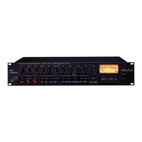
Art PRO CHANNEL II User manual

PRO CHANNEL II
TUBE PREAMP - OPTO COMPRESSOR - EQ
SERVICE MANUAL

II
IMPORTANT SAFETY INSTRUCTIONS – READ FIRST
This symbol, wherever it appears, This symbol, wherever it appears, alerts
alerts you to the presence of uninsulated you to important operating and maintenance
dangerous voltage inside the enclosure. Voltage instructions in the accompanying literature.
that may be sufficient to constitute a risk of shock. Please read manual.
Read instructions:
Retain these safety and operating instructions for future reference. Heed all warnings printed here and on the equipment.
Follow the operating instructions printed in this user guide.
Do not open:
Aside from one vacuum tube, there are no user serviceable parts inside. Refer any service work to qualified technical
personnel only.
Power sources:
Only connect the unit to mains power of the type marked on the rear panel. The power source must provide a good
ground connection.
Power cord:
Use the power cord with sealed mains plug appropriate for your local mains supply as provided with the equipment. If the
provided plug does not fit into your outlet consult your service agent. Route the power cord so that it is not likely to be
walked on, stretched or pinched by items placed upon or against.
Grounding:
Do not defeat the grounding and polarization means of the power cord plug. Do not remove or tamper with the ground
connection on the power cord.
Ventilation:
Do not obstruct the ventilation slots or position the unit where the air required for ventilation is impeded. If the unit is to be
operated in a rack, case or other furniture, ensure that it is constructed to allow adequate ventilation.
Moisture:
To reduce the risk of fire or electrical shock do not expose the unit to rain, moisture or use in damp or wet conditions. Do
not place a container of liquid on it, which may spill into any openings.
Heat:
Do not locate the unit in a place close to excessive heat or direct sunlight, as this could be a fire hazard. Locate the unit
away from any equipment, which produces heat such as: power supplies, power amplifiers and heaters.
Environment:
Protect from excessive dirt, dust, heat, and vibration when operating and storing. Avoid tobacco ash, drink spillage and
smoke, especially that associated with smoke machines.
Handling:
To prevent damage to the controls and cosmetics avoid rough handling and excessive vibration. Protect the controls from
damage during transit. Use adequate padding if you need to ship the unit. To avoid injury to yourself or damage to the
equipment take care when lifting, moving or carrying the unit.
Servicing:
Switch off the equipment and unplug the power cord immediately if it is exposed to moisture, spilled liquid, objects fallen
into opening, or the power cord or plug becomes damaged during a lightning storm or if smoke odor or noise is noted.
Refer servicing to qualified technical personnel only.
Installation:
Install the unit in accordance with the instructions printed in the user guide.

III
PRO CHANNEL II
TUBE PREAMP - OPTO COMPRESSOR - EQ
IMPORTANT SAFETY INSTRUCTIONS – READ FIRST......................................................................................................II
INTRODUCTION.....................................................................................................................................................................1
INSTALLATION......................................................................................................................................................................2
AC Power Hookup..................................................................................................................................................................................2
Analog Audio Connections.....................................................................................................................................................................2
FRONT PANEL CONTROLS and JACKS.............................................................................................................................3
Mic Preamp Controls..............................................................................................................................................................................3
Instrument Input .....................................................................................................................................................................................3
Gain Control...........................................................................................................................................................................................3
Impedance Control.................................................................................................................................................................................3
GAIN Switch...........................................................................................................................................................................................4
Phantom Power Switch ..........................................................................................................................................................................4
Invert Switch...........................................................................................................................................................................................4
Low Cut Control......................................................................................................................................................................................4
Preamp Output Control...........................................................................................................................................................................4
Tube Voltage Switch ..............................................................................................................................................................................5
Compressor Controls .............................................................................................................................................................................6
Threshold Control...................................................................................................................................................................................6
Ratio Control ..........................................................................................................................................................................................6
Attack Control.........................................................................................................................................................................................7
Release Control......................................................................................................................................................................................7
Compressor Output Control....................................................................................................................................................................7
Gain Reduction LED Meter.....................................................................................................................................................................8
Semi-Parametric EQ ..............................................................................................................................................................................8
EQ Bypass Switch..................................................................................................................................................................................9
CLIP LED ...............................................................................................................................................................................................9
Master Output Control............................................................................................................................................................................9
Output Meters.......................................................................................................................................................................................10
VU Meter Switches...............................................................................................................................................................................10
REAR PANEL CONNECTIONS...........................................................................................................................................11
INPUT Jack..........................................................................................................................................................................................11
PREAMP OUT Jack .............................................................................................................................................................................11
COMP IN Jack......................................................................................................................................................................................12
COMP OUT Jack..................................................................................................................................................................................12
EQ IN Jack...........................................................................................................................................................................................12
OUTPUT Jacks ....................................................................................................................................................................................12
OUTPUT LEVEL Switch.......................................................................................................................................................................12
APPLICATIONS....................................................................................................................................................................13
Bypassing Components Of The Pro Channel II....................................................................................................................................13
Optimizing The Preamp For Lowest Noise...........................................................................................................................................13
WARRANTY INFORMATION...............................................................................................................................................14
SERVICE...............................................................................................................................................................................27
SPECIFICATIONS................................................................................................................................................................28
LIST OF FIGURES
FIGURE 1 – Preamp section...................................................................................................................................................5
FIGURE 2 – Compressor Section...........................................................................................................................................6
FIGURE 3 – Equalizer Section................................................................................................................................................8
FIGURE 4 – Signal Flow Block Diagram ................................................................................................................................9
FIGURE 5 – Output Section..................................................................................................................................................10
FIGURE 6 – Rear Jacks........................................................................................................................................................11

1
INTRODUCTION
The ART Pro Channel II is the answer to your recording and computer audio interface needs. Our
second-generation discrete Class-A microphone preamp provides clean quiet gain while maintaining
incredible transparency. A powerful dynamics processor subtly controls transients and noise of the
most demanding sources. The ART Pro Channel II’s semi-parametric EQ offers wide tune-ability and
can be patched before OR after the dynamics processor. Separate insertion jacks allow you to use
your favorite external signal processing gear immediately after the Mic preamp and before the EQ
and dynamics processor. Both analog and LED meters provide a detailed indication of audio levels.
Key Features Include:
• Fully Featured discrete class "A" Tube Microphone Preamplifier
• ¼-inch High Z input on the front panel
• Selectable plate Voltage
• Variable Input Impedance
• Smooth musical sounding Optical Compressor
• Separate Attack and Release controls
• Auto/ Manual Attack/ Release switch
• Parametric EQ
• Large VU and LED meters
• Multi section clip monitor LED
• Selectable Source switches for VU signal monitoring of any section of the unit
• Two insert loops
• +4/-10 dB switch for optimal signal output levels
• Solid case
• Toroidal power transformer for low noise
• Vents for the 12AX7a and 12AT7 tubes.

2
INSTALLATION
The ART Pro Channel II may be used in a wide variety of applications and environments. In a rack-
mountable, all-steel enclosure, the unit is designed for continuous professional use. Mounting location
is not critical, however for greater performance reliability we recommend that you not place the unit
on top of power amps, or other sources of heat and/or strong magnetic fields. The tube circuitry
needs about a minute to “warm up” and stabilize from a cold power up.
AC Power Hookup
The ART Pro Channel II has an internal power supply. Only connect the unit to mains power of the
type marked on the rear panel. The power source must provide a good ground connection, and the
ground pin on the mains plug should never be defeated.
Analog Audio Connections
Audio connections to and from the Pro Channel II are:
Front panel Instrument input: [1/4-inch] Tip = Hot (+), Sleeve = Ground
Rear panel balanced input: [XLR] Pin 2 = Hot (+), Pin 3 = Cold (-), Pin 1 = Ground
Rear panel balanced output: [XLR] Pin 2 = Hot (+), Pin 3 = Cold (-), Pin 1 = Ground
Rear panel 1/4-inch output: Tip = Hot (+), Sleeve = Ground
Rear panel 1/4-inch insert inputs: Tip = Hot (+), Sleeve = Ground
Insert Outputs: Tip = Hot (+), Sleeve = Ground

3
FRONT PANEL CONTROLS and JACKS
Mic Preamp Controls
The Pro Channel II input consists of a discrete Class-A differential preamp. The circuit is optimized
for low impedance microphones as well as line level signals. Up to 56dB of gain is available from this
stage. The output can be inverted using the INVERT switch.
The impedance of the rear XLR input is continuously variable for fine-tuning the preamp to a wide
variety of mics. Phantom power is available on the XLR input as well.
A selectable low-cut filter removes rumble, wind noise, and pops, thereby increasing clarity.
Instrument Input
The 1/4-inch T/S jack on the front panel provides a high impedance unbalanced input, and when
used, automatically switches off the mic pre-amp. (The rear XLR balanced input is lower impedance
and is part of the mic pre-amp. The rear jack is not intended to be used with high impedance
microphones or instruments.)
Gain Control
This control adjusts both the mic pre-amp gain as well as the instrument input gain. The gain
marked applies to the mic pre-amp without the GAIN switch depressed. Refer to the APPLICATIONS
section to learn how to optimize the gain control for low noise operation.
Impedance Control
This knob sets the load impedance at the rear panel XLR input of the Pro Channel II. Use the
IMPEDANCE CONTROL to subtly tune the sound of your microphone. Various microphones will
change their sound at differing load impedances. The correct setting is subjective. Adjust this control
to personal taste.

4
GAIN Switch
This switch increases the tube gain by 20dB to support low output mics and instruments. It should
only be used when the GAIN control cannot provide enough gain.
Phantom Power Switch
The switch safely applies +48Volt phantom power to the XLR input. Use phantom power only when
the microphone that you are using requires it. Doing so will extend the life of the Pro Channel II as
well as reducing the possibility of shock hazard.
Invert Switch
This switch selects the output phase of the Pro Channel II. There is a 180-degree phase shift
through the Pro Channel II preamp section when lit.
Low Cut Control
This control allows adjustment of a 6dB/Oct high pass filter from 10Hz to 250 Hz. The filter is
designed to remove rumble, pops, and wind noise, yet still sound natural.
Preamp Output Control
This control adjusts the output of the Preamp section allowing up to 10dB of gain or allowing you to
mute the output when fully CCW.

5
Tube Voltage Switch
The vacuum tube preamp section can be adjusted to run at two different plate voltages. Refer to
Figure 1 for the location of the switch.
Choose the “NORMAL” setting for adding warmth to the input signal. This setting has an increased
amount of tube saturation at higher signal levels.
Choose the “HIGH” setting to increase overall gain, headroom, and bandwidth.
NOTE: The change between tube voltage modes is gradual, taking 10 to 20 seconds to be fully activated.
FIGURE 1 – Preamp section

6
Compressor Controls
The ART Pro Channel II Compressor section consists of an above threshold Optical
Compressor/Limiter with adjustable slope. The attack and release controls allow a wide range of
adjustment while the complex detector assures fast response without distortion.
Threshold Control
This control sets the level, above which the Compressor in the Pro Channel II starts to act on the
input signal. As the control is turned clockwise, more input signal is required to begin reducing gain.
The compression action can be seen in the Gain Reduction LED meter.
Ratio Control
The RATIO control sets the amount of gain reduction that takes place based on how far the input
signal is over the threshold level (set by the THRESHOLD control). A good starting point for vocals is
2.5:1.
To have the unit act as a limiter, set the RATIO control to ∝:1
FIGURE 2 – Compressor Section

7
Attack Control
The ATTACK control sets the time it takes the Compressor/Limiter to respond to increases in signal
level (by reducing gain). You can use this control to shape the “front end” of the dynamics envelope.
One example is to listen to a snare hit and adjust the attack control. A short attack makes the snare
sound “thin”. As the attacks go longer (and the knob is turned clockwise) you should hear more of the
thump in the compressed snare. The downside is that this creates an overshoot, (a large transient),
the length of which is the time set by the ATTACK control.
Overshoots less than 1 msec are very hard to hear even when they are clipped. If the attack is set
too fast, the gain may be reduced too much and thereby create a “pumping” sound
1
. One way to
eliminate this is to use the LOW CUT filter to remove plosive sounds in vocals that can make the
detector overreact.
Release Control
The RELEASE control sets the time the Compressor/Limiter takes to increase the gain after the
input level drops.
Longer settings maintain the dynamics of the input signal, while shorter settings reduce the
dynamics. Shorter settings will also increase the apparent reverberation, and at extreme gain
reduction settings, lead to “breathing” artifacts
2
.
Compressor Output Control
The Output control can provide from10dB of gain recovery to fully muting the output. It adjusts the
output level provided to the COMP output jack.
1
“Pumping” in a Compressor/Limiter sounds like the processor over-reacts to the increase in level and has reduced the
volume too much.
2
“Breathing” is the sound of the Compressor/Limiter turning up the gain so quickly you can hear breathing noises between
words during vocal processing.

8
Gain Reduction LED Meter
The GAIN REDUCTION meter displays the Compressor's attenuation action. The meter covers a
very large range while offering high resolution.
Semi-Parametric EQ
The ART Pro Channel II offers a four-band semi-parametric equalizer. The entire EQ can be
bypassed with a single switch. Each band has + 12dB of control range.
The High and Low EQ bands are shelving type with a switch selectable turnover point.
The two Mid bands can be continuously tuned over a three-octave range, plus a range switch adds
another three-octave range. You can adjust the filter "Q" to be either narrow or wide via separate
switches.
FIGURE 3 – Equalizer Section

9
EQ Bypass Switch
This switch allows you to instantly set the EQ completely flat without loosing the current EQ settings.
CLIP LED
This LED indicates clipping in any section of the Pro Channel II.
You can isolate the source of the clipping to the INPUT section by reducing the Preamp output, if
the clipping LED remains lit. If the Clip LED goes out, the clipping is in the compressor or EQ section.
You can prevent clipping in the EQ section by reducing the Compressor output.
FIGURE 4 – Signal Flow Block Diagram
Master Output Control
The OUTPUT LEVEL control provides gain or attenuation to adjust for a variety of system operating
levels. This control affects the levels sent to the A/D converter and to the balanced analog OUTPUT
jacks.

10
Output Meters
The ART Pro Channel II provides both analog VU and LED level meters.
The analog VU meter displays the signal level various points of the processor depending on the
setting of the VU Meter Switches. “0” VU on the analog VU meter corresponds to +4dBu on the
balanced output.
The upper LED bargraph displays how hard the tube section is being driven (Warmth). The last two
LEDs in the meter are marked “Clip” indicating that the preamp section's gain is set too high.
VU Meter Switches
These switches allow you to monitor the level at the Preamp output, Compressor output, EQ section
or the Main output.
When both switches are out (POST/MAIN) the meter displays the output level at the Output jack of
the unit.
When the Pre switch only is depressed (PRE/MAIN) the meter monitors the EQ section output (Pre
output level control). The actual point that is monitored is After the EQ Bypass switch.
Depressing the Second switch allows you to see the levels before or after the Compressor. If Post is
selected the signal after the Compressor Bypass switch is displayed (the same signal present on the
Comp Out jack on the rear panel). Depressing the PRE and COMP switches select the output of the
Preamp section (the same signal present on the Preamp Out jack on the rear panel).
FIGURE 5 – Output Section

11
REAR PANEL CONNECTIONS
FIGURE 6 – Rear Jacks
INPUT Jack
This XLR jack provides balanced inputs to the microphone preamplifier. The input impedance of the
XLR connection is variable by the front panel Impedance knob.
The Front panel 1/4-inch Instrument input overrides the rear jack when it is used.
PREAMP OUT Jack
This 1/4-inch T/S unbalanced jack provides a direct signal from the microphone preamplifier, ahead
of the EQ and dynamics processors. This output can be used in conjunction with the INSERT INPUT
jack to insert external signal processors between the main preamp section and the compressor of the
Pro Channel II.

12
COMP IN Jack
This 1/4-inch T/S unbalanced jack is an input to the EQ and dynamics processing sections. This
input can be used in conjunction with the MIC PREAMP OUTPUT jack to insert external signal
processors between the main preamp section and the EQ and dynamics processing of the Pro
Channel II.
COMP OUT Jack
This 1/4-inch T/S unbalanced jack provides a direct signal from the microphone preamplifier, ahead
of the EQ and dynamics processors. This output can be used in conjunction with the INSERT INPUT
jack to insert external signal processors between the main preamp section and the EQ and dynamics
processing of the Pro Channel II.
EQ IN Jack
This 1/4-inch T/S unbalanced jack is an input to the EQ and dynamics processing sections. This
input can be used in conjunction with the MIC PREAMP OUTPUT jack to insert external signal
processors between the main preamp section and the EQ and dynamics processing of the Pro
Channel II.
OUTPUT Jacks
The analog output of the Pro Channel II is available on both a 1/4-inch unbalanced jack and an XLR
balanced jack. The XLR output is active balanced, and will adjust to balanced or unbalanced
termination without gain change.
OUTPUT LEVEL Switch
This switch optimizes the output level of the Pro Channel II depending on the equipment you are
driving.
When this switch is in the out position, the balanced output measures -10dBV (about 0.3V RMS).
This is the appropriate setting when connecting to most semi-pro or consumer equipment.
When depressed, the XLR output of the unit measures +4dBu (about 1.2 Volts RMS) when the
Output Meter reads "0" VU. Use this setting when connecting up to professional line level gear.

13
APPLICATIONS
Bypassing Components Of The Pro Channel II
To bypass the vacuum tube microphone preamp: Use the preamps INSERT INPUT jack instead
of the Instrument or Mic input jack.
To bypass the Compressor/Limiter: Use the COMP bypass switch.
To bypass the EQ: Use the EQ bypass switch.
Optimizing The Preamp For Lowest Noise
The preamp of the ART Pro Channel II can be optimized for low noise by combining use of the PAD
and Input GAIN control for mic and line level signals. NOTE: The PAD control has no effect on the
INSTRUMENT INPUT (Front panel 1/4-inch input of the INPUT combo jack).
First, bypass the Compressor/Limiter, Expander/Gate and EQ. Next center the OUTPUT LEVEL
control to “0” dB of gain. The OUTPUT LEVEL LED meter can now be used to correctly indicate the
clip level of the input stage.
Second, start with the PAD in the “OUT” position and the GAIN control centered. Refer to the
OUTPUT LEVEL LED meter’s peak-hold function. Make sure that this meter never indicates clipping
(the red LED is held on after a transient). The peak-hold indicator can be in the “yellow” range or in
the –5dB range of levels.
If the signal level is too high, depress the PAD switch.
Third, adjust the GAIN control to keep the peak levels in the –5dB range of the OUTPUT LEVEL
LED meter.

14
Repair Parts
ART Part #
Value Description
Footprint QTY
LOCATION
POTENTIOMETER SECTION
1001027215 100K 20C POT-16DUAL-H Pot, Dual Element 2 VR16-HI-MID,
VR17-LO-MID
1001027214 100K A POT-16SGL-H POT - Single Control
/
Trimmer 1 VR14-ATTACK
TIME
1001027213 100K B POT-16SGL-H POT -
Single Control /
Trimmer 2 VR5-RATIO,
VR15-RELEASE
1001027212 10K 15C POT-16DUAL-H Pot, Dual Element 3
VR1-GAIN, VR2-
LOCUT, VR4-
THRESHOLD
1001027209 10K 5C POT-16DUAL-H Pot, Dual Element 1 VR12-
IMPEDANCE
1001027210 20K 15A POT-16SGL-H POT -
Single Control /
Trimmer 1 VR6-COMP OUT
1001027216 20K B POT-16SGL-H POT -
Single Control /
Trimmer 6
VR3-PREAMP,
VR7-LOW, VR8-
LO-MID, VR9-HI-
MID, VR10-
HIGH,
VR11-MASTER
OUT
1001010101 25K Trim PT10V POT -
Single Control /
Trimmer 1 VR13-VACTROL
CALIBRATE
TUBE SECTION
1001202101 12AT7 TUBE-W/SHLD Tube, Dual Triode (9-
pin)
w/Mounting Holes 1 V3
1001200101 12AX7 TUBE-W/SHLD Tube, Dual Triode (9-
pin)
w/Mounting Holes 1 V1
JACK AND INTERFACE SECTION
1005225103 J-CLIFF-GOLD J-CLIFSTER
Jack, Stereo 1/4 in Phone,
Horizontal PCB mount 2 J4-RETURN, J6-
INSERT RETURN
1005225102 J-CLIFF-STEREO J-CLIFSTER
Jack, Stereo 1/4 in Phone,
Horizontal PCB mount 4
J1-
INPUT UNBAL,
J3-OUTPUT
UNBAL, J5, J7-
SENDS
1005291101 XLR-MALE/FEM XLR-MF-H Jack, XLR Male-
Female
PCB Mount 1 J2-XLR INPUT
DISPLAY SECTION
LEDREPAIRKIT Complete BACK LIGHT
CKT BOARD 1 M1
1002005107 VU METER W/tbox
NISSEI TN73 W/O
BEZEL 1 M1
SWITCH SECTION
1005022104
SW-4PDT-TA SW-4PDT-FH-LIT2
Switch, 4PDT, PCB Mount 2 SW8, SW15
1005022102
SW-DPDT-FH SW-DPDT-FH-LIT2
Switch, DPDT, PCB mount
14
SW1, SW2,
SW3,SW4, SW5,
SW7, SW9,
SW10, SW11,
SW12, SW13,
SW14, SW16,
SW17

15
ART Part #
Value Description
Footprint QTY
LOCATION
MISC SECTION
1001043101 VTL5C2 VACTROL Vactrol, LED-
LDR, Single
Element 1 VCT1
215AINLAY Inlay gain reduction meter 1
MECHANICAL SECTION
1005269103 SWT power switch swt rocker pwr spst 1
1001510101
TRANSFORMER, TOROID
22V-0-
22V 120/240V
TD00785
1
100-5052-107 .75" KNOB /BLACK
TAIWAN KNOB
42006-2G-D (TKE) 2 Gain and Master
100-5052-108 0.5" KNOB /BLACK
TAIWAN KNOB
42006-4G-D (TKE) 14 All other pots
1642004101 LIT SWITCH CAP 16
SW1, SW2,
SW3,SW4, SW5,
SW7,SW8, SW9,
SW10, SW11,
SW12, SW13,
SW14,SW15,
SW16, SW17

16
Full Bill of Materials
ART Part #
Value Description
Footprint QTY
LOCATION
RADIAL CAPACITOR SECTION
1001037116 .001uF RADIAL0.2 Capacitor, Film / Ceramic
2 C25,C60
1001037101 0.0068 RADIAL0.2 Capacitor, Film / Ceramic
2 C41, C51
1001037105 0.01 RADIAL0.2 Capacitor, Film / Ceramic
2 C50, C55
1001037110 0.068 RADIAL0.2 Capacitor, Film / Ceramic
1 C42
1001009109 0.22 RADIAL0.2 Capacitor, Film / Ceramic
2 C37, C39
1001032101 0.68 RADIAL0.2FAT Capacitor, Film / Ceramic
2 C8, C11
1001037111 0.1 RADIAL0.2 Capacitor, Film / Ceramic
8 C27, C28,
C34, C35,
C45, C54, C71, C73
1001038101 100pF m RADIAL0.1 Capacitor, Film / Ceramic
4 C16, C47, C56, C85
1001036102 150pF m RADIAL0.1 Capacitor, Film / Ceramic
1 C2
1001036101 330pF m RADIAL0.1 Capacitor, Film / Ceramic
3 C3, C7, C66
1001036103 33pF m RADIAL0.1 Capacitor, Film / Ceramic
2 C5, C23
ELECTROLYTIC CAPACITOR SECTION
1001162112 1,000uF 35V LYTIC.2
Capacitor, Electrolytic
(polarized) 2 C74, C78
1001162124
100uF 100V LYTIC.2 Capac
itor, Electrolytic
(polarized) 1 C72
1001162125
100uF 200V LYTIC.2
Capacitor, Electrolytic
(polarized) 2 C202, C203
1001162120 100uF 63V LYTIC.2-SM
Capacitor, Electrolytic
(polarized) 13
C22, C49, C53, C63,
C75, C76, C77, C79,
C89, C90, C91, C200,
C201
1001162250 100uF/250V LYTIC.3
Capacitor, Electrolytic
(polarized) 1 C15
1001162104 10uF 50V LYTIC.1
Capacitor, Electrolytic
(polarized) 8
C10, C30, C46, C52,
C67, C69, C70, C93
1001008102
1uF 50V LYTIC.1
Capacitor, Electrolytic
(polarized) 2 C38, C82
1001162122 2.2uF 50V LYTIC.1
Capacitor, Electrolytic
(polarized) 3 C6, C20, C81
1001162114
220uF 6.3V LYTIC.1
Capacitor, Electrolytic
(polarized) 10
C9, C13, C17, C21,
C24, C26, C43, C44,
C65, C92
1001162117 22uF 25V LYTIC.1
Capacitor, Electrolytic
(polarized) 8
C31, C33, C36, C48,
C57, C58, C61, C94
4.7uF/50V LYTIC.1
Capacitor, Electrolytic
(polarized) 1 C80
1001162109 47uF 25V LYTIC.1
Capacitor, Electrolytic
(polarized) 8
C1, C4, C14, C18, C19,
C68, C83, C84
1001162110
470uF 25V LYTIC.2-SM Capacitor,
Electrolytic
(polarized) 1 C12
AXIAL CAPACITOR SECTION
1001005104 220pF CAP-AXIAL Capacitor, Film / Ceramic
1 C62
1001005117 470pF CAP-AXIAL Capacitor, Film / Ceramic
1 C59

17
ART Part #
Value Description
Footprint QTY
LOCATION
1001005120 680pF CAP-AXIAL Capacitor, Film / Ceramic
1 C40
AXIAL RESISTOR SECTION
1001001301 1.00K AXIAL0.4
Resistor, Carbon Film,
1% 8
R6, R7, R26, R27, R28,
R42, R172, R179
1001002176 1.5K AXIAL0.4
Resistor, Carbon Film,
5% 1 R183
1001002191 10 AXIAL0.4 Resistor, Carbon Fi
lm,
5% 2 R219, R222
1001001401 10.0K AXIAL0.4
Resistor, Carbon Film,
1% 38
R3, R8, R9, R10, R14,
R25, R32,
R35, R40,
R49, R57, R58, R60,
R61, R62, R65, R66,
R67, R69, R70, R127,
R131, R136, R137,
R138, R141, R147,
R155, R157, R165,
R177, R195, R203,
R208,
R212, R213,
R215, R216, R217
1001002103 100 AXIAL0.4
Resistor, Carbon Film,
5% 14
R1, R50, R52, R54,
R79, R96, R105, R108,
R112, R115, R159,
R192, R193, R206
1001002134 100K AXIAL0.4
Resistor, Carbon Film,
5% 13
R11, R46, R48, R63,
R76, R126, R146,
R168
, R169, R170,
R231, R233, R241
1001002118 10K AXIAL0.4
Resistor, Carbon Film,
5% 1 R19
1001002150 12K AXIAL0.4
Resistor, Carbon Film,
5% 1 R44
1001002192 150 AXIAL0.4
Resistor, Carbon Film,
5% 4
R124, R181, R191,
R244
1001002120 16K AXIAL0.4 Resistor,
Carbon Film,
5% 4
R153, R163, R166,
R196
1001002114 1M AXIAL0.4
Resistor, Carbon Film,
5% 15
R15, R22, R39, R97,
R102, R106, R111,
R113, R132, R134,
R145, R149, R152,
R154, R224
Table of contents
Other Art Amplifier manuals
Popular Amplifier manuals by other brands

Cary Audio Design
Cary Audio Design CAD 300 SE Signature owner's manual

Alpha Communications
Alpha Communications TekTone PK292A installation instructions

Wheelock
Wheelock PAMX-125 installation instructions

Electro-Voice
Electro-Voice 1.0kW Lightweight specification

Cornered Audio
Cornered Audio CA280DSP user manual

Denon
Denon PMA-700V Service manual