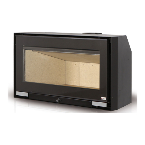
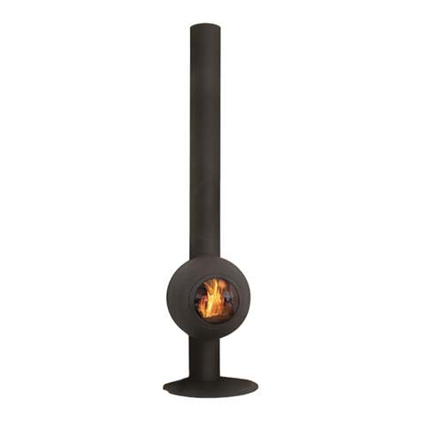
ARTE NIREAS Instruction Manual


TABLE OF CONTENTS
1. Arte®Fireplace - A Greek Quality Product ...........................................................................................................................................................................................................................................................2
2. Facts about wood and the enviroment................................................................................................................................................................................................................................................................2
2.1. Why use wood?...................................................................................................................................................................................................................................................................................................2
2.2. Buying firewood...................................................................................................................................................................................................................................................................................................2
2.3. Storing your wood...............................................................................................................................................................................................................................................................................................2
2.4. Wood types and calorific value ......................................................................................................................................................................................................................................................................3
2.5. Determining the heat output ...........................................................................................................................................................................................................................................................................4
3. Endorsements & Certifications.................................................................................................................................................................................................................................................................................5
3.1. Endorsement ........................................................................................................................................................................................................................................................................................................5
3.2. Declaration of Performance CE......................................................................................................................................................................................................................................................................5
3.3. Features marking plate......................................................................................................................................................................................................................................................................................5
4. Packaging....................................................................................................................................................................................................................................................................................................................5
4.1. Unpacking the fireplace ...................................................................................................................................................................................................................................................................................5
5. Fire safety......................................................................................................................................................................................................................................................................................................................6
5.1. Safe distances .....................................................................................................................................................................................................................................................................................................6
5.2. Wooden beams protection..............................................................................................................................................................................................................................................................................6
5.3. General security instructions.............................................................................................................................................................................................................................................................................6
5.4. Flue security instructions ....................................................................................................................................................................................................................................................................................6
5.4.1. Basic requirements for proper flue operation..................................................................................................................................................................................................................................6
5.4.2. Chimney placement .............................................................................................................................................................................................................................................................................7
5.4.3. Chimney cap ..........................................................................................................................................................................................................................................................................................7
5.4.4. Connecting the fireplace with the flue.............................................................................................................................................................................................................................................8
5.4.5. Malfunction - Secure fireplace shutdown ........................................................................................................................................................................................................................................8
6. Connecting Nireas to the central heating installation.......................................................................................................................................................................................................................................8
6.1. Connecting the water supply and return......................................................................................................................................................................................................................................................9
6.2. Overheating protection ....................................................................................................................................................................................................................................................................................9
6.2.1. System with closed expansion tank when the fireplace is at the same level with the heaters .........................................................................................................................................10
6.2.2. System with closed expansion tank when the fireplace is below the heaters.......................................................................................................................................................................11
6.2.3. System with open expansion tank....................................................................................................................................................................................................................................................12
7. Operating Instructions .............................................................................................................................................................................................................................................................................................13
7.1. Before using the ARTE® NIREAS fireplace for the first time.......................................................................................................................................................................................................................13
7.2. About ARTE® NIREAS fireplace ......................................................................................................................................................................................................................................................................13
7.3. General information.........................................................................................................................................................................................................................................................................................14
7.3.1. When the fireplace paint dries..........................................................................................................................................................................................................................................................14
7.3.2. Incineration preparation ....................................................................................................................................................................................................................................................................14
7.3.3. Combustion air intake .........................................................................................................................................................................................................................................................................14
7.3.4. Power failure..........................................................................................................................................................................................................................................................................................14
7.3.5. Heating during seasonal change or in adverse weather conditions.......................................................................................................................................................................................15
7.4. Adjusting the combustion air .........................................................................................................................................................................................................................................................................15
7.4.1. Adjusting the combustion air with fader (STANDARD).................................................................................................................................................................................................................15
7.4.2. Automatic regulator of the heating circuit for water heating fireplace with air intake control (RT-08G) .......................................................................................................................15
7.4.2.1. Using the regulator...............................................................................................................................................................................................................................................................................16
7.4.2.2. Screens ...................................................................................................................................................................................................................................................................................................17
7.4.2.2.1. OPERATION screen...............................................................................................................................................................................................................................................................................17
7.4.2.2.2. SYSTEM OPERATION screen ................................................................................................................................................................................................................................................................17
7.4.2.2.3. MODE screen ........................................................................................................................................................................................................................................................................................17
7.4.2.3. TIME ZONES mode ................................................................................................................................................................................................................................................................................18
7.4.2.4. SECONDARY CONTROL RELAY mode..............................................................................................................................................................................................................................................18
7.4.2.5. TIME ADJUSTMENT screen ...................................................................................................................................................................................................................................................................18
7.4.2.6. PARAMETERS SETTING screen.............................................................................................................................................................................................................................................................18
7.4.2.7. ALARM screen.......................................................................................................................................................................................................................................................................................19
8. Lighting the fireplace...............................................................................................................................................................................................................................................................................................20
8.1. Traditional method of lighting........................................................................................................................................................................................................................................................................20
8.2. Lighting without CO emissions (FROM TOP TO BOTTOM) .........................................................................................................................................................................................................................20
9. Tertiary Combustion .................................................................................................................................................................................................................................................................................................21
10. Cleaning & Maintaining the Fireplace ..............................................................................................................................................................................................................................................................22
10.1. External maintenance ...................................................................................................................................................................................................................................................................................22
10.2. Internal maintenance....................................................................................................................................................................................................................................................................................22
10.2.1. Ash disposal ...........................................................................................................................................................................................................................................................................................22
10.2.2. Glass........................................................................................................................................................................................................................................................................................................22
10.2.3. Gasket.....................................................................................................................................................................................................................................................................................................23
10.2.4. Internal parts that need maintenance ...........................................................................................................................................................................................................................................23
10.2.5. Chimney sweeping..............................................................................................................................................................................................................................................................................23
10.2.6. Annual maintenance..........................................................................................................................................................................................................................................................................23
10.2.7. How to clean the inside parts of ARTE® NIREAS fireplace ..........................................................................................................................................................................................................24
10.3. Internal parts removal....................................................................................................................................................................................................................................................................................24
10.4. Inactive fireplace for prolonged periods ..................................................................................................................................................................................................................................................24
11. Tips & Tricks for Resolving Issues ...........................................................................................................................................................................................................................................................................24
12. Dimensions ...............................................................................................................................................................................................................................................................................................................25
13. Technical Specifications .......................................................................................................................................................................................................................................................................................26
14. Warranty ...................................................................................................................................................................................................................................................................................................................27
14.1. Warranty terms ................................................................................................................................................................................................................................................................................................27
14.2. Excluded from the warranty.........................................................................................................................................................................................................................................................................27
14.3. Responsibility....................................................................................................................................................................................................................................................................................................27
14.4. Emergency maintenance ............................................................................................................................................................................................................................................................................27
14.5. Responsibility for installation .........................................................................................................................................................................................................................................................................27
14.6. Usage.................................................................................................................................................................................................................................................................................................................27
14.7. Legal guarantee .............................................................................................................................................................................................................................................................................................27

INSTALLATION &USER MANUAL WATER HEATING FIREPLACE | NIREAS
2 | Page
1. ARTE®FIREPLACE -AGREEK QUALITY PRODUCT
Thank you for buying an ARTE®fireplace - we believe that you will have as much pleasure from our product as we have.
Your ARTE®fireplace is made in such a way, to extract the maximum possible energy from the wood with the minimum possible emissions,
using the most innovative technology and the most robust design - made in Greece!
These instructions contain interesting and informative facts and all you need to know about the subjects of heating, wood, and operating
your ARTE®fireplace. Please read these instructions carefully before using your fireplace for the first time and keep them in a safe place.
2. FACTS ABOUT WOOD AND THE ENVIRONMENT
2.1. Why use wood?
With proper forest management, burning wood does not deplete the earth’s resources. Heating with wood usually does not contribute to
global warming. The young trees that replace the trees in your fireplace absorb carbon dioxide from the air. Burning firewood releases only as
much CO2 as the tree has absorbed from the atmosphere during its growth. Wood rotting in the forest generates the same amount of CO2 as
the same wood burning.
Besides being environmentally friendly, the heat from a fireplace warms you like the warming rays of the sun during the sunny winter days. It is
the radiated heat that transmitted by electromagnetic waves in the infrared range. Even when the air is very cold you can feel the warm rays
of the sun on your skin.
Another advantage to wood is that it is produced locally, which creates local employment, and more tax revenues stay in the province.
2.2. Buying firewood
Where can I get my firewood?
Regenerated ready-to-burn firewood can be purchased from dealers:
Fireplace ready, stored for at least two years
Pre-dried, stored for one year
Fresh from the forest
Whether you have cut your own wood or bought it, the important thing is: the wood should be dried for at least two years before it is burned.
2.3. Storing your wood
The full potential for heat will not be realized if you neglect the simple chore of piling and protecting your wood. Proper storage is essential to
avoid moisture, bacteria, and insect problems in your home.
To avoid problems with insects and moisture, store the wood as far from your house as is practical. Do not store wood in your basement; one
cord of wood can give off more than 500 liters of water. The basic rule is to hide the wood from water, but not from the sun or wind (Pic. 2.3.1
& 2.3.2) Green wood will dry slowly or not at all if unprotected, while seasoned wood left unprotected may become unseasoned.
There are three basic rules to follow when storing wood:
Allow air circulation by piling one tier wide if possible
Protect wood from rain and snow by covering with a tarp or woodshed roof.
Pile wood off the ground on scrap lumber or wooden pallets.
The time-honored way to cure wood is to buck, split, and stack
wood off the ground for one full year. How-ever, wood can
generally be reduced to 20 per cent moisture content in two to
three months. The ideal 10% to 15% may take longer (almost 18
months).
The ideal residual moisture is 12 - 15% and should be no higher!
The manuals which are enclosed with the product must be
kept throughout the product’s entire service life.
Pic. 2.3.1
Pic. 2.3.2

ΕΓΧΕΙΡΙ∆ΙΟ ΕΓΚΑΤΑΣΤΑΣΗΣ &ΧΡΗΣΗΣ WATER HEATING FIREPLACE | NIREAS
3 | Σελίδα
2.4. Wood types and calorific value
A wood’s efficiency does not depend only on its type, but also on its humidity, as well as the temperature of the combustion chamber.
For more efficient and longer burning, without emission of hazardous substances, woods must be dry. Ideally, their humidity percentage must
not exceed 10% to 15%.
If this percentage is over 20%, the wood is not burned properly, whereas if the piece of wood has been cut recently, the humidity is over 60%
making it unsuitable for burning. The reason for that is that the fire will be weak and pale and will produce dense smoke, unburned tar and
creosote, soiling the ceramic glass and the flu.
It is preferable to get your wood supplies during the summer months and store them, to ensure better combustion quality during the winter.
Useful tips
Always choose dry firewood.
Avoid wood that pops (chestnut, conifers such as cedar, spruce and pine), as they may damage your fireplace or the flue.
Pay attention to the size of the logs. Good firewood must have been cut at least twice.
You should prefer oak, beech, olive wood, which is hard wood with high density since they will burn for longer.
Briquettes
They ignite very easily, and burn slowly. They are economically advantageous because you will burn smaller quantities compared to common
firewood and they are easily stored. Also, you have less quantity of ashes vs. to wood.
Birch
It’s a soft wood that ignites easily with great thermal energy production. It produces less smoke and ash compared to other wood and burns
silently. The same characteristics apply for lime and chestnut.
Beech
Hard wood is ideal for firewood but requires a high temperature to ignite. It weights a lot; it is dense and burns with a calm and long fire for a
WET
DRY
0% humidity
100% thermal efficiency
10%
humidity
88%
thermal efficiency
30%
humidity
63%
thermal efficiency
50%
humidity
39%
thermal efficiency

INSTALLATION &USER MANUAL WATER HEATING FIREPLACE | NIREAS
4 | Page
longer time. Best when well seasoned. The same applies for oak, but seasoned for 2-3 years.
The various wood types have various calorific values
Wood type Thermal capacity (Kcal/h-1Kg)
Briquette 5.000
Birch 4.800
Walnut 4.731
Oak 4.619
Beech 4.578
Fir 4.588
Common Oak 4.548
Pine 4.457
Olive 4.100
Poplar
4.022
Table 2.4.1
860Kcal/h = 1 kW/h
The values are based on 15% residual wood moisture.
2.5. Determining the heat output
There is not a specific rule that enables the calculation of the required heat output. This depends on the amount of space that is required to
be heated and mostly on its insulation. In average the required heat output for a properly insulated room and with external temperature of 0ο
is 40 kCal/h per m3.
Taking into account that 1kW equals 860 kCal/h an equivalent of 50W/m3can be used. For example, to heat a 50 m3room (10 x 6 x 2.5m) in
an insulated residence, the output required is 150m3x 50W/m3= 7500W or 7.5 kW.
So for the main heating, a 10kW appliance is enough.
Indicative combustion value
with efficiency ~80%
Required amount relative
to 1kg dry wood
Fuel Unit kCal kW
Firewood (moisture 15%) kg 3600 4.2 1.00
Firewood (moisture 50%) Kg 1850 2.2 1.95
Wood briquettes Kg 4000 5.0 0.84
Coal briquettes Kg 4800 5.6 0.75
Coal Kg 7700 8.9 0.47
Coke Kg 6780 7.9 0.53
Gas m37800 9.1 0.46
Diesel L 8500 9.9 0.42
Electricity kW/h 860 1.0 4.19
Table 2.5.1
An ARTE®fireplace can be fired with all of the above wood types

ΕΓΧΕΙΡΙ∆ΙΟ ΕΓΚΑΤΑΣΤΑΣΗΣ &ΧΡΗΣΗΣ WATER HEATING FIREPLACE | NIREAS
5 | Σελίδα
3. ENDORSEMENTS &CERTIFICATIONS
3.1. Endorsement
The ARTE® fireplace you chose has been tested according to EN13229.
3.2. Declaration of Performance CE
The constructor G. Karnoutsos & Co. declares that ARTE® fireplaces meet the requirements of the standard EN 13240, also the product’s
performance according to the quality specifications are monitored on a permanent basis.
3.3. Features marking plate
ARTE® fireplace’s feature marking plate is located on the right side of the appliance.
4. PACKAGING
ARTE® is devoted in protecting the environment, so we use as much recyclable materials as possible and the least amount of packaging
materials without compromising the secure transfer of our products.
4.1. Unpacking the fireplace
1. The product will be delivered on a wooden palette which is lined with wooden side panels and top panel. (Pic. 4.1.1)
2. Firstly remove the side panels. (Pic. 4.1.2)
3. Carefully remove the plastic membrane and the waterproof plastic film and also all the polystyrene on the outside and inside of the
product.
4. Unscrew the 4 screws located on the bottom side of the product, in order to release the fireplace from the palette. (Pic. 4.1.3)
5. Carefully pick up the product and place it on the installation point, making sure that the floor can withstand the weight of the device. If
the existing construction cannot withstand the weight of the device, a load distributing plate is necessary. Also, make sure you provide
proper insulation in case the floor is built using flammable materials.
Pic. 4.1.1
Pic. 4.1.2
Pic. 4.1.3

INSTALLATION &USER MANUAL WATER HEATING FIREPLACE | NIREAS
6 | Page
5. FIRE SAFETY
It is OBLIGATORY to respect the National and European rules and local regulations concerning building matter and fireproof rules.
The installation MUST be inspected by a qualified auditor, prior to lighting the fireplace. Also the appropriate local authorities must be
informed.
5.1. Safe distances
The combustion chamber opening must be AT LEAST 80cm away from any flammable materials that are inside the
heat radiation zone.
5.2. Wooden beams protection
Given its properties, heat is transmitted through radiation. In case there are any wooden beams inside the radiation zone or in the way of the
hot air, the MUST be properly insulated because the continuous exposure in high temperatures can make them deteriorate faster or even
cause self ignition. Use proper insulation materials that are in accordance with European rules or, in case of high thermal stress you can also
use metal linings.
5.3. General security instructions
Never leave children alone or without supervision near the fireplace when it is lit.
Teach children how to operate the fireplace correctly and safely.
Never touch the external surfaces of the fireplace or the glass when it is lit. There is a high risk of burns!
Due to the self closing door, you have to be extra careful when you are filling the fireplace.
It is forbidden to use the fireplace as a waste incinerator.
Don’t use burned or used wood as fuel.
Remove the ash only after it has completely cooled off.
Ash should be placed outdoors or be disposed in a place where there is no risk of ignition.
Immediately inform your specialized local supplier if you find any malfunction.
Don’t use chemicals or liquids as fire starters.
Do not use ANY fuel other than the recommended.
5.4. Flue security instructions
Prior to installing the fireplace ARTE® the chimney sweep or a qualified technician should check the condition and operation of your chimney
in accordance with the standards EN13384-1 & EN13384-2.
This way you ensure the best conditions for heating without issues.
5.4.1. Basic requirements for proper flue operation
The internal section of the flue must preferably be circular. In a case of square or rectangular
flue, the internal corners should have a radius of at least 20mm. In case of rectangular flue,
the ratio of the sides should be at maximum 1: 1.5.
The flue must be properly insulated and waterproof and constructed of materials with
thermal resistance and resistance to combustion products and any deposits.
The flue must have no constrictions; it must have a vertical path and it should not change in
direction that exceeds 45o. (Pic. 5.4.1.1)
In case of an existing flue the construction material should be checked. Materials such as
cement with lime, galvanized steel and rough or porous materials are contraindicated as
they create issues in the correct operation of the fireplace. Also, a proper study for the flue
size must be conducted because often old flues have quite large diameters. This means that
the amount of air draft is not proportional to the heat generated by the fireplace and by
extension means that you consume more wood than necessary and will spend more time
on maintenance. The solution proposed in these cases is the connection of an inner tube inside the flue. This tube should extend over the
whole length of the flue and at no point should exceed in diameter the outlet flue of the fireplace. If the existing flue has the desired
diameter a proper cleaning by qualified personnel should be done.
Follow the operating instructions supplied with the product to help prevent fire and
protect the environment.
Pic. 5.4.1.1

ΕΓΧΕΙΡΙ∆ΙΟ ΕΓΚΑΤΑΣΤΑΣΗΣ &ΧΡΗΣΗΣ WATER HEATING FIREPLACE | NIREAS
7 | Σελίδα
Inserting the pipe along the outer wall must be properly studied to avoid heat loss. This solution, however, is contraindicated, as positioning
the flue inside the house warms more spaces as heat of the flue remains in the house
5.4.2. Chimney placement
The placement of the chimney on the roof is a particularly decisive factor in the convection of the fireplace.
An incorrectly fitted chimney may generate reimbursement of exhaust into the heating space due to down flow of the air.
Follow the instructions below to ensure proper dissipation of smoke. (Pic. 5.4.2.1)
The ending of the chimney must be at least 50cm above the top of the roof.
If there is more than one chimney on the roof, they must be positioned at least 2m apart.
If there are two adjacent chimneys, their ends must be at least 50cm apart.
If there is a tall building or tree next to the house, then you should place the chimney at a distance greater than 5m from the obstacle.
It is prohibited to connect several devices to the same chimney. Every chimney should be autonomous. (Pic. 5.4.2.2)
In case of an inclined roof, the height of the chimney is defined depending on the inclination and the distance of the chimney from the
ridge according to the following table. (Pic. 5.4.2.3)
Inclination
αο
RIDGE – CHIMNEY
DISTANCE
MIN HEIGHT
ABOVE THE RIDGE
Α(m) H (m)
15ο
< 1,85 m 0,50 m OVER THE RIDGE
> 1,85 m 1,00 m OVER THE ROOF
30ο
< 1,50 m 0,50 m OVER THE RIDGE
> 1,50 m 1,30 m OVER THE ROOF
45ο
< 1,30 m 0,50 m OVER THE RIDGE
> 1,30 m 2,00 m OVER THE ROOF
60ο
< 1,20 m 0,50 m OVER THE RIDGE
> 1,20 m 2,60 m OVER THE ROOF Pic. 5.4.2.3
Table 5.4.2.1
5.4.3. Chimney cap
The chimney draft depends broadly on the adequacy of the cap.
So, in case the chimney is built, its exhaust diameter should be at least twice the inside diameter of the chimney. Knowing that it is necessary
to protrude from the ridge of the roof, the cap must ensure the proper smoke dissipation in case of strong wind.
A chimney cap must meet the following requirements:
Internal diameter must be equal to the diameter of the chimney.
Exhaust diameter be at least twice the inside diameter of the chimney.
It should be constructed in such a way as to avoid the entrance of rain, snow and any foreign body in the chimney.
It can be checked, maintained and cleaned easily.
Pic. 5.4.2.2
Pic. 5.4.2.1
Industrial style cap with
protective net
Cap with deflector. It leans
according to the wind and it
provides very good smoke
dissipation
Cap with fan. It provides
very good smoke
dissipation even in case
of weak winds

INSTALLATION &USER MANUAL WATER HEATING FIREPLACE | NIREAS
8 | Page
5.4.4. Connecting the fireplace with the flue
t is necessary that the flue gas tube is connected to a certified conduit with the same
diameter as the fireplace, by following the dimensions of the adjacent image. (Pic. 5.4.4.1).
For fireplace NIREAS the diameter of the flue is 180mm. The flue must be properly insulated
with stone wool with thickness of 4cm with external aluminum foil. Do not use fiberglass or
paper based insulation. Also, do not use flexible thin walled metallic tubes or asbestos
tubes. This tube should be perfectly sealed and well insulated throughout its length.
To install the flue, you must place it on the fireplace outlet and then seal it using the
appropriate sealant.
The space extending around and over the device up to the deflector must be ventilated
continuously. For this reason you must allow cool air from a lower spot, for example, the
bottom and the outlet of the hot air from above. (Pic. 5.4.4.2)
These openings must remain free and not able to be covered. The must also have a
minimum surface of 300 cm2, for example, a grille with size 30x10cm.
This way you achieve:
greater security
increase on the heat of the room, due to the air circulating around the device.
The hot air extract grille must be placed on top of the trunk approximately 20cm from the
ceiling. The grille must always be installed, as its purpose is to allow, the heat that builds up
inside the trunk to be released in the room and also to relieve the pressure created.
The hot air extract grille can also serve as a visiting slot in order for the installer or the user to have access to the
electronics box of the air regulator (STANDARD type) and be able to perform maintenance, like changing the
rechargeable batteries.
5.4.5. Malfunction - Secure fireplace shutdown
In rare occasions even a test fire may not cause sufficient draft in the flue. In this case contact your chimney sweep.
Under no circumstances should you try to light a larger fire. If smoke escapes from the fireplace, ventilate the room immediately and contact
your chimney sweep. DON’T LIGHT THE FIREPLACE!
6. CONNECTING NIREAS TO THE CENTRAL HEATING INSTALLATION
ARTE® NIREAS fireplace can be installed to work individually or in collaboration with any another water heating device to be used for central or
floor heating.
To ensure the safety of the device you must install an overheating safety valve (Pic. 6.1), in order to protect the system against possible
overheating. Also in case of floor heating, it is necessary to use a buffer tank (Pic. 6.2) and a thermal mixing valve (Pic. 6.3) to ensure constant
temperature of the water in the floor pipes.
Pic. 6.1 Pic. 6.2 Pic. 6.3
The installation is made by using 1 1/4” hoses.
Pic. 5.4.4.1
Pic. 5.4.4.2

ΕΓΧΕΙΡΙ∆ΙΟ ΕΓΚΑΤΑΣΤΑΣΗΣ &ΧΡΗΣΗΣ WATER HEATING FIREPLACE | NIREAS
9 | Σελίδα
The construction of the fireplace allows you to use any combination of water supply and return and always gives you the
maximum water temperature. This is achieved thanks to the special partitioning of the water chamber that causes the water to
follow certain paths from the intake to the outlet of the water chamber. (Pic. 6.4). Thus the hottest water located around the
upper part of the water chamber in not mixed with the less hot water that is below. This enables you to connect the return and
supply of water in any combination you want and not only diametrically opposite as is common in these types of installations.
6.1. Connecting the water supply and return
ARTE® NIREAS provides you with 4 different water supply intakes and 4 return outlets. In order to connect the fireplace with the water circuit
you must use 11/4” pipe joints. (Pic. 6.1.1). The fireplace is delivered with 6 out of 8 joints already closed. In order to correctly connects the
pipes to the circuit or seal (if applicable) the remaining joints you must use hemp or/and thread glue.
In any case the installation must be made by a qualified technician and in accordance local law and the regulations
of each country, including all regulations referring to national and European standards.
The installation can be set into operation only after it has been tested by a qualified inspector. Prior to installing the
new fireplace please contact the appropriate local authorities.
The following schemes in chapters 6.2.1, 6.2.2 and 6.2.3, show the various options for connecting the fireplace to the
water heating circuit along with the proposed security devices.
6.2. Overheating protection
In order to ensure the integrity of the device and the heating network, ARTE® provides you with an option to place a safety configuration to
protect the water jacket from overheating.
Pic. 6.2.1
On the back of the water jacket of ARTE® NIREAS fireplace there are cold water supply joints that are used by the overheating protection
system (Table 7.2.1, Line 9). You must install an overheating safety valve on the input joint (Pic. 6.1) and place its temperature sensor in the
copper tube (Table 7.2.1, Line 11).
In case the water temperature in the jacket exceeds 95oC, the overheating safety valve will be activated and it will insert cold water in the
independent overheating protection system located inside the water jacket, thus rapidly dropping the water temperature and preventing
the possibility of destroying the device, without mixing the cold water with the water of the jacket (Pic. 6.2.1).
NEVER connect or use the fireplace without it being
connected to the water heating circuit!
Pic. 6.4
Pic. 6.1.1

INSTALLATION &USER MANUAL WATER HEATING FIREPLACE | NIREAS
10 | Page
6.2.1. System with closed expansion tank
when the fireplace is at the same level with the heaters
17. Water mixing valve*
*Used only in case of heater map
installation
13. Water pump
14. Automatic filling valve
15. Closed expansion tank
16. ARTE® NIREAS fireplace
9. Fan coil heater
10. Radiator or heater mat
11. Temperature/pressure gauge
12. Three way valve for by-pass
5. Drainage
6. Water distribution box
7. Buffer tank
8. Hot water
1. Automatic vent valve
2. Thermometer
3. Overheating safety valve
4. Safety relief valve

ΕΓΧΕΙΡΙ∆ΙΟ ΕΓΚΑΤΑΣΤΑΣΗΣ &ΧΡΗΣΗΣ WATER HEATING FIREPLACE | NIREAS
11 | Σελίδα
6.2.2. System with closed expansion tank
when the fireplace is below the heaters
17. Water mixing valve*
*Used only in case of heater map
installation
13. Water pump
14. Automatic filling valve
15. Closed expansion tank
16. ARTE® NIREAS fireplace
9. Fan coil heater
10. Radiator or heater mat
11. Temperature/pressure gauge
12. Three way valve for by-pass
5. Drainage
6. Water distribution box
7. Buffer tank
8. Hot water
1. Automatic vent valve
2. Thermometer
3. Overheating safety valve
4. Safety relief valve

INSTALLATION &USER MANUAL WATER HEATING FIREPLACE | NIREAS
12 | Page
6.2.3. System with open expansion tank
13. Water pump
14. Water mixing valve*
*Used only in case of heater map
installation
15. Open expansion tank
9. Fan coil heater
10. Radiator or heater mat
11. Temperature/pressure gauge
12. Three way valve for by-pass
5. Drainage
6. Water distribution box
7. Buffer tank
8. Hot water
1. Automatic vent valve
2. Thermometer
3. Overheating safety valve
4. ARTE® NIREAS fireplace
ARTE® NIREAS fireplace is delivered with a stainless steel cooling coil already installed in which you must install a
cold water supply (Table 7.2.1, Line 9) so in case the water inside the water jacket exceeds 95o C the
overheating safety valve (Pic. 6.1) will open and rapidly cool the water jacket.

ΕΓΧΕΙΡΙ∆ΙΟ ΕΓΚΑΤΑΣΤΑΣΗΣ &ΧΡΗΣΗΣ WATER HEATING FIREPLACE | NIREAS
13 | Σελίδα
7. OPERATING INSTRUCTIONS
7.1. Before using the ARTE® NIREAS fireplace for the first time
One of our qualified representatives has already provided you with instructions on how to operate the ARTE® NIREAS fireplace that you just
acquired.
The operating instructions below describe in detail the steps to follow so you do not encounter any difficulties during the operation of the
fireplace.
The qualified dealer in your area will be at your disposal to answer any questions. NIREAS fireplace is equipped with the following control
systems:
7.2. About ARTE® NIREAS fireplace
The fireplace that you just received is a device designed to offer excellent heating distribution in the area with a very high degree of
efficiency and thus elevate the thermal coefficient of your house.
1
Main door with ceramic crystal
9
Overheating system joints
2
Main door opening handle
10
Hot water outlets
3
Cleaning port
11
Temperature sensor copper tube
4
Door lock rod
12
Joints for var
ious safety valves and sensors
5
Fireplace base
13
Flue
6
Combustion air adjustment fader
(STANDARD type)
14
H
ot air outlets (natural flow)
7
Cold
water
intake
s
15
Metal frame
8
A
ir regulator
d
rive motor
for p
rimary combustion
16
Combustion chamber
Table 7.2.1

INSTALLATION &USER MANUAL WATER HEATING FIREPLACE | NIREAS
14 | Page
1 Secondary combustion air holes
2 Primary combustion air intake
3 Secondary combustion air intake
4 Lower air curtain
5 Automatic flue damper restore adjustor
6 Upper air curtain
7 Water heating tubes
8 Automated & adjustable flue damper
9 Flue gas baffle
10 Temperature sensor copper tube
11 Water jacket
12 Water jacket insulation
Table 7.2.2
7.3. General information
7.3.1. When the fireplace paint dries
ARTE ® products are painted in spray booth with as more environmentally friendly and ecological colors as possible. There is although a
possibility that the first few times the fireplace is lighted, the paint emits an odor. Let the fire burn with intense convection until all traces of
gas disappear and there is no longer a smell. The gas is not toxic, but the room should be well ventilated.
7.3.2. Incineration preparation
Prepare sufficient amount of chopped firewood, kindling and branches or torches. Before using the wood it is recommended to store them
in a warm place for a few days.
7.3.3. Combustion air intake
Although the fireplace uses external air for combustion, make sure that the room is ventilated adequately when the fireplace operates
with external fresh air. When you open the door of the combustion chamber for adding firewood there should be no pressure difference
between outdoor and indoor air in the room, so it is good to keep the door open for about 1.5cm for 5-6 seconds and then fully open it.
7.3.4. Power failure
In case of power failure, the automatic air intake regulator does not stop operating as it is also powered by rechargeable batteries that
allow it to continue its operation for almost 12 hours. So, when the temperature drops to normal levels then the regulator smoothly feeds
back air in the combustion chamber and the operation of the fireplace is continued. However the water pump must also operate. That’s
why it is suggested using an uninterruptible power supply unit (UPS) which will ensure the smooth operation of the pump and therefore the
fireplace.
UNDER NO CIRCUMSTANCE SHOULD YOU OPERATE THE FIREPLACE WITH THE
MAIN DOOR OPEN. YOU RUN A SERIOUS RISK OF DESTROYING THE DEVICE!!!
If you want to import air from an external source, you must apply the corresponding
100mm diameter collar and clamps to mount a flexible conduit.
The air intake must be positioned so as not to allow being covered.
The air intake must be communicating with the combustion space
and protected by a grille.
The minimum surface of the air intake should not be less than
~110cm2
Avoid using air intakes connected with garages, kitchens,
bathrooms or boiler rooms
.

ΕΓΧΕΙΡΙ∆ΙΟ ΕΓΚΑΤΑΣΤΑΣΗΣ & ΧΡΗΣΗΣ WATER HEATING FIREPLACE | NIREAS
15 | Σελίδα
7.3.5. Heatin durin seasonal chan e or in adverse weather conditions
When there is high h midity or fog, with temperat res ≥15 ° C, b t also d ring the transitional period between seasons, it is recommended
to light a test fire before normally lighting the fireplace. This will displace the cold, heavy air that is inside the fl e and create the right
conditions for optim m smoke dissipation
Also the a tomatic fl e damper restore adj stor (Table 7.2.2, Line 5) enables yo to adj st the damper to remain open in any position
desired, even with the main door closed, in order to ens re adeq ate convection, depending on the season.
• D ring winter → Damper closed
• D ring spring/a t mn → Damper open
Do adj st the damper restore se the provided Ν
ο
6 hexagonal key. By t rning the screw clockwise yo open the damper while
respectively by t rning it co nter clockwise yo close it. (Pic. 7.3.5.1 & 7.3.5.2)
Pic. 7.3.5.1 Pic. 7.3.5.2
7.4. Adjustin the combustion air
ARTE® NIREAS fireplace gives yo the opport nity to adj st the primary comb stion air intake by 2 different ways. Yo can either se the fader
(Table 7.2.1, Line 6) which is located on the frame (STANDARD system) or yo can se the a tomatic control panel (AUTOMATIC system). In
both cases the adj stment is made by controlling an electric motor where the changes made either on the fader or the control panel are
transferred to the comb stion air intake damper. To prevent overheating, they are eq ipped with a sensor positioned in the copper t be
(Table 7.2.2, Line 10) of the water jacket where in the case of overheating the device closes the s pply of comb stion air.
7.4.1. Adjustin the combustion air with fader (STANDARD)
By adj sting the fader (Table 7.2.1, Line 6) the electronic board can adj st the fresh air intake damper in any position desired.
If the water temperat re exceeds 85
o
C, the damper is closed in order to red ce the comb stion air and is ret rned to the original setting
when the water temperat re drops to 75
o
C. In case the water temperat re exceeds 90
o
C and for as long as it remains above this
temperat re the device emits an a dible warning signal. The safety device operates on 220V power b t it is also eq ipped with
rechargeable batteries that in case of a power fail re they contin e the operation of the damper for 8-9 ho rs.
Chan in the batteries
If the battery performance drops below a safe operating limit, the safety device will emit a do ble beep every 30 seconds, at which time
they sho ld be replaced by sing the following proced re..
1. Disconnect the device from the power.
2. Caref lly remove the box containing the electronic board and sing a small screwdriver rotate half a t rn the plastic screws and very
caref lly remove the lid (Pic. 7.4.1.1)
3. Open the Velcro fastener that holds the batteries in the cover and replace them with rechargeable batteries that have same
feat res (AAA-R3 700mAh) (Pic. 7.4.1.2).
4. Reseal and place the box back in its place.
Pic. 7.4.1.1 Pic. 7.4.1.2
7.4.2. Automatic re ulator of the heatin circuit

INSTALLATION &USER MANUAL WATER HEATING FIREPLACE | NIREAS
16 | Page
for water heating fireplace with air intake control (RT-08G)
The regulator controls the intensity of the combustion in the fireplace by adjusting the combustion air damper, so as to maintain the water
temperature in the fireplace to a desired, predetermined level.
This results in enabling the regulator, in a second phase, when the water reaches a predetermined temperature to activate the pump of the
heating circuit (HC) as well as the domestic hot water circulating pump (DHW).
It regulates not only the start and end of the circulators but it also has the option, when the user wishes it, to give a periodic priority to the DHW
pump in correlation to the HC pump. Recurrent priority means that it alternately activates the HC pump for 45 seconds and then suspends it for
the next 4 minutes thus resulting in heating the DHW faster.
It also has the option to shut down another heat source (e.g. gas boiler) when operating the fireplace or to command an additional pump or
motorized valve (solenoid) with a maximum power of 500W.
!The regulator has an ANTI-FREEZE system which protects the heating circuit from potential freezing when the measured temperature is
below 4oC, by automatically activating the HC pump.
!The regulator has an ANTI-CLOG system which operates the heating circuit pumps for one minute per week during the period that the
device is not used.
The regulator is equipped with its own emergency power source so a power supply interruption up to 8 seconds would not impair its smooth
operation. In case o an outage longer than that, an uninterruptible power supply device can be used (UPS). For safety reasons, if the
regulator is not receiving power, the damper closes completely and is automatically placed in the rest position (fully closed).
7.4.2.1. Using the regulator
All of the regulator functions can be controlled via the control panel (Pic. 15.1.1). When the regulator is not operating, the light (1)
illuminates amber to notify that it is in standby mode and the screen displays the water temperature in the water jacket, the time and the
time zone (if it is enabled). To activate the control panel press the F1 (3) key once. To disable it hold the same key pressed for about 1
second.
1 Operation
light
Red
→
failure
Amber
→
Stand by
Green
→
Normal operation
Flashing green
→
Manual operation
2 Graphic display screen
3 F1 Key ON/OFF
4 PLUS Key
5 MINUS Key
6 CONFIRM parameters Key
7 TOGGLE parameters Key
8 F2 Key (ESC- cancel + return to the main display)
The device status is indicated in the graphic display screen (2) in the form of text and images. It also includes information on the operation of
individual system components, temperature sensors and it allows changing parameters.
Switching between the different displays is done by the TOGGLE (7) key. When you are in a display that allows any parameter change you
must press the CONFIRM (6) key. The parameter field will start flashing and you can now change the value by pressing the (4) or (5)
keys. If any display has more than one parameter fields, move between them with the TOGGLE (7) key and by pressing the CONFIRM (6)
key register that change.
!If you do not register the altered parameter within 10 seconds, it will be ignored by the regulator. The field will stop flashing and the
parameter will revert to its previous value.
1
2
3
4
8
5
7
6

ΕΓΧΕΙΡΙ∆ΙΟ ΕΓΚΑΤΑΣΤΑΣΗΣ &ΧΡΗΣΗΣ WATER HEATING FIREPLACE | NIREAS
17 | Σελίδα
7.4.2.2. Screens
7.4.2.2.1. OPERATION screen
It displays the current temperature of the water in the water jacket of the fireplace and the degree of the air damper in percentage. This
screen is fixed and to change it you must press the TOGGLE (7) key.
Water jacket
temperature (Τ3)
Current
time
Time zone
(if enabled)
Air intake dumper
opening degree
Set
temperature
Air intake dumper
operation mode
In this screen you can change the temperature in the water jacket of the fireplace. By pressing the CONFIRM (6) key the set temperature
parameter field will start flashing. Press (4) or (5) to change the value and then press the CONFIRM (6) key in order to register the
change.
Also in this screen, when the MANUAL mode is selected and the operation light (1) flashes green, you can manually adjust the position of
the air intake damper position in 10% increments. By pressing the (4) key it opens and by pressing the (5) key it closes.
7.4.2.2.2. SYSTEM OPERATION screen
Water jacket
temperature (Τ3)
DHW pump
status
DHW buffer tank
temperature (T1 & T2)
HC pump
status
Secondary control
relay status
Current
time
Time zone
(if enabled)
DHW pump
operation mode
This screen is fixed and to change it you must press the TOGGLE (7) key.
7.4.2.2.3. MODE screen
It allows changing the way the fireplace operates and manages the DHW and HC pumps.
The table below presents the different modes of operation of the fireplace.
ICON MODE DESCRIPTION
ON The air intake damper is automatically adjusted in order to stabilize the temperature in the water jacket of the
fireplace. If this mode is selected the operation light (1) illuminates green.
MANUAL
Block automatic control and thus the air intake damper setting and consequently the temperature in the
water jacket of the fireplace is made manually. If this mode is selected the operation light (1) flashes
green.
OFF The air intake damper remains in the neutral position, i.e. completely closed. If this mode is selected the
operation light (1) is off.
AUTO Activate the automatic cycle mode Ignition - Operation - Shutdown. If this mode is selected the operation
light (1) illuminates green during the operation of the fireplace and it turns of when it detects shutdown.
AUTO
(start/finish) This icon appears before the beginning and after the end of AUTO mode.
Press the F1 (3) key to activate AUTO mode. The air intake damper opens and light (1) turns on. Within the next 2 hours, the fireplace
should be lit and the water temperature should have reached the specified desired value. From that moment on, a drop in the water
temperature above 10 oC which is maintained for 30 minutes is treated as a shutdown of the fireplace.
If this occurs, the regulator terminates the cycle by setting the air intake damper to the neutral position (closed). If you press the F1 (3) key
again, a new automatic cycle will begin.

INSTALLATION &USER MANUAL WATER HEATING FIREPLACE | NIREAS
18 | Page
The table below presents the different modes of management of the DHW and HC pumps.
ICON MODE PUMP STATUS
OFF
DHW Closed
HC Open
SUMMER
DHW Open
HC Closed
ON
DHW Open
HC Open
PRIORITY*
DHW Open alternately
DHW: 4’
HC: 45”
HC
*When DHW ≥60οC, return to ON mode
7.4.2.3. TIME ZONES mode
The regulator allows you to operate your fireplace with automatic switching between modes
based on certain time zones, using the CLOCK and SPECIAL modes.
!The regulator time zones are not enabled. Activation and potential adjustment to the parameters must be made in agreement with the
installer and if you understand the way they operate. Any careless changes can cause unstable and inefficient system operation..
7.4.2.4. SECONDARY CONTROL RELAY mode
The regulator is equipped with a secondary control relay system whose contacts can be
used, for example, to stop the operation of another heat source (e.g. gas boiler) or to
command an additional pump or solenoid when the water temperature reaches a
predetermined value.
7.4.2.5. TIME ADJUSTMENT screen
The screen displays the current time and the current time zone (when their feature is enabled).To
adjust the hour press the CONFIRM (6) key, so the minutes field start flashing. Press the (4) ή
(5) keys to change the value and the press the TOGGLE (7) key to switch to the time field. After
you finish adjusting the hours field press the CONFIRM (6) button to register the change (the time
field will stop blinking).
7.4.2.6. PARAMETERS SETTING screen
In the first view of the parameters display there is the definition of "Parameters Level" with the default value "0"
which means that the parameters are not available.
After changing the level to "1", "2", "3" or "4", the following views on the display show the
parameter values in the image on the right. The last screen displays "****" which ends the
definition of the operation parameters, followed by a return to the first screen.
CLOCK SPECIAL
Relay deactivated(NO)
Relay activated (NC)
Time zone
(if enabled)
Ονοµασία
παραµέτρου
Μονάδα
µέτρησης
Άνω & κάτω όριο
παραµέτρου
Τιµή
παραµέτρου

ΕΓΧΕΙΡΙ∆ΙΟ ΕΓΚΑΤΑΣΤΑΣΗΣ &ΧΡΗΣΗΣ WATER HEATING FIREPLACE | NIREAS
19 | Σελίδα
!The parameters adjust the regulator according to the properties of the fireplace and of the central heating installation. The new settings
must be in agreement with the installer and the manufacturer of the fireplace. Any careless changes can cause unstable and
inefficient system operation.
!If you make a change for which you are not sure and you have not registered, press the F2 (3) key to return to the main display.
7.4.2.7. ALARM screen
This screen is displayed when there is one of the following situations:
•Failure of the sensor on the top of the buffer tank (T1). The screen displays
WAW temp. sensor (T1) damaged. If the sensor is not installed, the alarm is not activated.
•• Failure of the sensor on the bottom of the buffer tank (T2). The screen displays
WAW temp. sensor (T2) damaged. If the sensor is not installed, the alarm is not activated.
•Failure of the sensor on the water jacket of the fireplace (T3). The screen displays
Fplace temp. sensor (T3) damaged.
•Exceed on the limit of the temperature in the water jacket of the fireplace. The screen displays
Too high temp. of the fireplace.
The alarm is accompanied by an intermittent acoustic signal, which can be canceled by pressing the CONFIRM (6). key. Also when there is
a temperature exceeding alarm, the HC pump automatically starts in order to cool the fireplace down.
Κείµενο
συνα ερµού
Table of contents
Other ARTE Indoor Fireplace manuals
Popular Indoor Fireplace manuals by other brands

Continental Fireplaces
Continental Fireplaces CVFS60N Installation and operating instructions
Duraflame
Duraflame DFI-550-39 manual

abc home living
abc home living 25685 instruction manual
SEI
SEI SUSSEX BRAID FA8566 Assembly instructions
Desa
Desa P324E OWNER'S OPERATION AND INSTALLATION MANUAL
Jøtul
Jøtul GI 450 DV Katahdin Installation and operation instructions

MHSC
MHSC LSTF36 Installation and operating instructions
Agio
Agio 1031550 Assembly instructions

Dimplex
Dimplex Cassette 500 Retail Optimyst operating instructions
Montigo
Montigo L42DF ST Installation & maintenance manual
Comfort Glow
Comfort Glow CF26NT OWNER'S OPERATION AND INSTALLATION MANUAL
foc.us
foc.us nemofocus Specific instructions


