artemisсomponentsmanual Side ТoSide
lnputs
and
Outputs
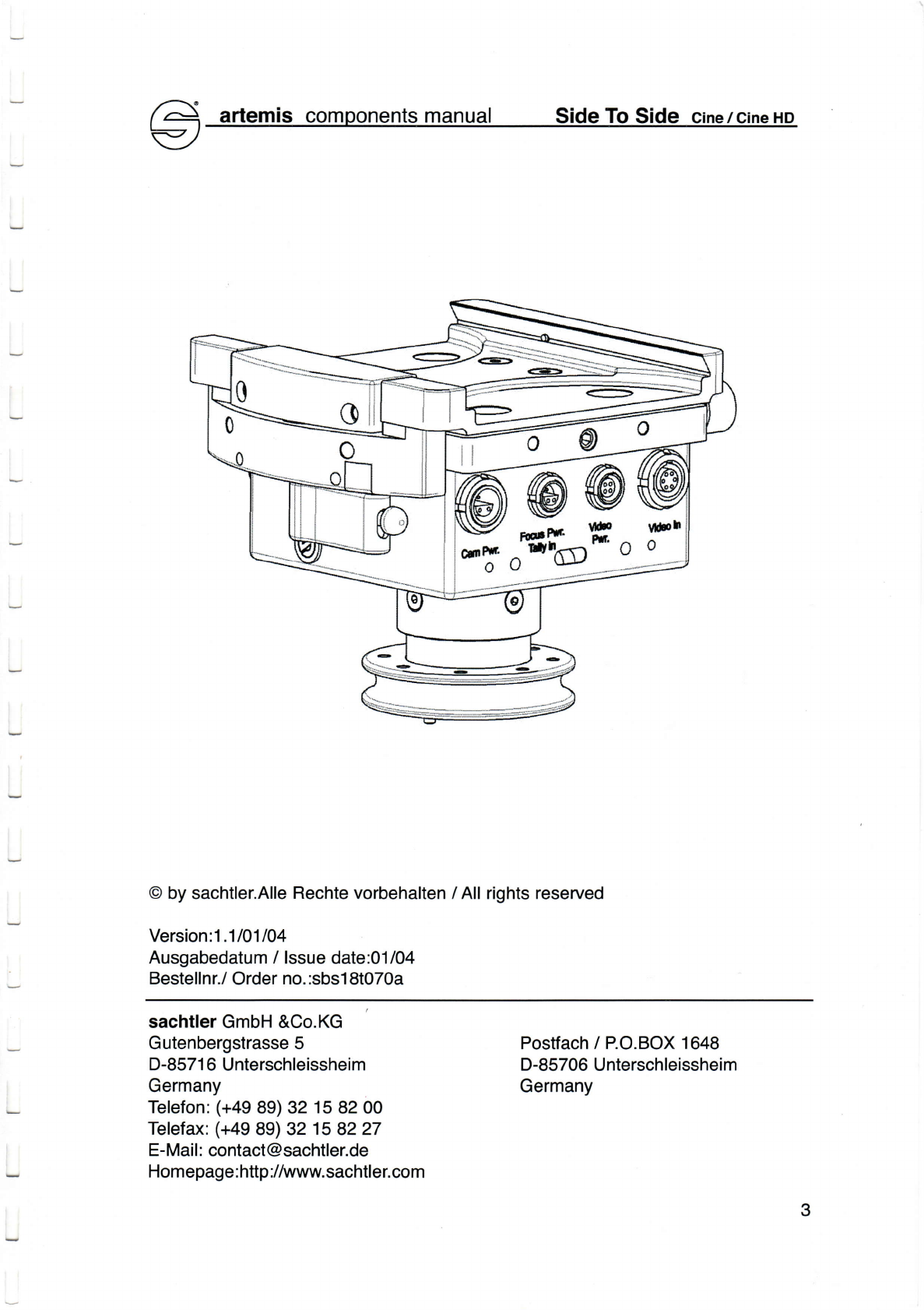
12Vl24VCаmeraPower
out
Тhese
socketsaIways
supp|y
12vdс
сamera
power.
After
se|eсting
24Yo||
these
soсkets
provide
eхtra24vсdсamerа
power.
Тhese
soсkets
сan
power
aссessories
(сamera
onboard|ight,....)withmax.
3
Amps/
25Watts.
ln12Vo|tmode,
these
soсketsare
powered
bythe
Camera.Battery,
in24VoItmode
bythe
Camera-BattandtheMoilCam-Battery.
FoсusPower
out/TallySignalln
These
soсkets
provide
two
funоtions:
Focus PowerOut:
Suppy|ingvariousremotefoсus
сontro|s
(Genio,
Fox,eоt.)with12
VDC.
The
Cаmera
вattery
powers
these
outputs.
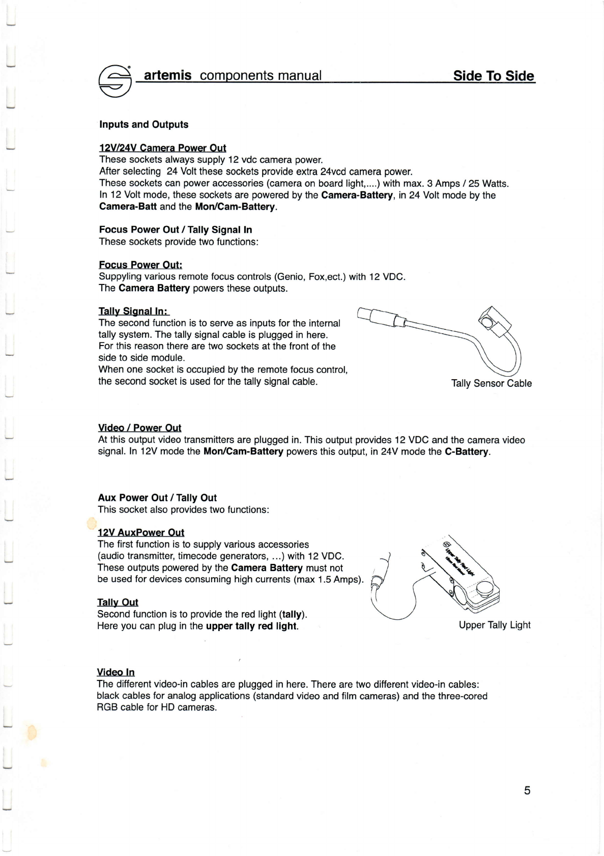
TаllySignalln:
Тheseсondfunсtionistoserveas inputsfortheinternal
tally
system.Тheta|ly
signa|
сab|eis p|ugged
inhere.
Forthisreason
therearetwo
soсketsatthefrontofthe
sidetosidemodule.
Whenone soсketisoсcupiedbytheremotefoсusсontrol,
theseсond
soсket
is used
forthe
ta||ysigna|сab|e. Тa||y
Sensor
Cable
Video / Power Out
Atthis
output
video
transmitters
areplugged
in.Тhisoutput
provides
12vDс andthe
сamera
video
signal.ln 12Vmode
the
Mon/Cam-Battery
powers
thisoutput,in24Y modetheC-Battery.
AuxPower
out/Tа|lyout
Тhis
soсketalso
provides
twofunсtions:
12VAuxPower Out
Тhefirst
funсtionistosupp|y
various
acсessories
(audio
transmitter,timecode
generators,
...)with
12VDс.
These
outputs
powered
by
the
CameraBattery
must
not
beusedfor
deviсesсonsuminghighсurrents
(max
1.5Amps).
TаIly
out
Seсondfunсtionistoprovide
the
red|ight
(tally).
Here
you
сanp|ug
in
theuppertally red light. Upper
Тa||yLight
Video ln
Тhedifferent
video-in
cab|esare
p|ugged
inhere.Thereare
twoditferent
video.inсab|es:
blaсkсab|esforana|ogapp|iсations
(standard
video
and
film
сameras)andthe
three-сored
RGB сab|e
forHDсameras.
5