ARTHUR HOLM ERT 30 User manual

User manual
AERT 30/ ERT 60
›IP TO RS422 Interface control

2
User manual About us
The company
Arthur Holm has its origins in the Danish furniture designer Jorgen Alex Jensen, who was active during the sixties and the
seventies. His design inspiration and his concept of ergonomics have been continued by his family, the design force behind
Arthur Holm product range. The result of combining Scandinavian design tradition with Mediterranean creativity, flexibility and
emotion is a wide product range built on more than 20 years of craftsmanship.
Arthur Holm offers a professional product range where tomorrow’s technology is shaped into valued materials with design
flexibility and customisation, specially created to enhance communication and collaboration in reception, conference and
meeting areas.
The art of customisation
Arthur Holm offers a range of ingenious products whose designs are based on quality materials and the latest technology.
Products which endow meeting and conference rooms with silent, ergonomic, innovative and aesthetic solutions that integrate
into the furniture, hang from the walls as works of art or are used as interactive points of information.
The world of Arthur Holm
Arthur Holm offers a selection of unique, elegant, versatile, flexible and ergonomic products that are being used in meeting and
conference rooms, reception areas, auditoriums and public zones of leading companies throughout the world.
The numbers speak for themselves! We currently own 27 product patents, have presence in over 45 countries with products and
solutions in more than 20,000 installations.
It will be our pleasure to work with you, designing your unique environment. Our broadcast electronic engineers will provide the
latest technology while our design team will offer you the most exclusive appearance.
Our team puts its heart, passion and pride in all our designs.
Technology serving Design

3
User manual Welcome
Thank you for purchasing an ARTHUR HOLM product.
Our product range has been designed to create the perfect meeting room, where the screens are a part of the interior design
as well as essential communication tools.
Please read these installation and operation instructions carefully and keep them in a safe place for future reference.
We remain at your disposal if you have any suggestions that would help us improve our products.
Henrik Holm
General Manager

4
User manual Table of contents
EC Normative and Security Norms 6
Box Contents 8
Controls & Connector 9
System Cionfiguration 11
AHNet Adress Configuration 16
AHnet Protocol 18
Disposal Information 21

5
User manual EC Normative and Security Norms
Safety instructions
ATTENTION: Do not disassemble or modify the device in any way
This symbol warns of the presence of dangerous non-insulated voltages inside some
of the components, which are high enough to cause risk of electric shock.
This symbol draws attention to important use and maintenance instructions in the
manual that accompanies the unit.
This symbol indicates that the equipment conforms to the norms established by the
European Community.
PLUGS
Do not dismantle any part of the monitor power connector.
Disconnect the power plug from the AC outlet when the monitor is not going to be used for a long period.
POWER AND EXTENSION CORDS
Use the appropriate power cord with the correct plug type.
Do not overload wall outlets or power cords.
Make sure the total ampere passed through an extension cord does not exceed the maximum allowed by the cable used.
Do not place anything on the power cord.
Do not locate this product where a person may trip or walk over the cord.

6
User manual EC Normative and Security Norms
ENVIRONMENT
Install the equipment on an elevated flat surface.
Install the equipment in a ventilated area.
Avoid exposing the equipment to:
›Rain or water
›Excessive heat, cold or humidity
›Areas exposed to direct sunlight
›Dirty areas
›Equipment generating strong magnetic fields
Avoid placing open containers of liquid near the equipment.
Keep a minimum distance of 30mm to ensure good ventilation.
Never place any sources of flames, such as lighted candles, etc, above the device.
If you are using the device in extreme weather conditions and/or tropical climates, the equipment should be installed in a
room which ensures a reasonable level of temperature and humidity.
To prevent any damage, the equipment must be firmly anchored to the surface, as the installation instructions state.
Wiring connected to hazardous voltage requires installation by qualified
personnel or the use of ready-made flexible cables
For your safety, your equipment must be connected to an electrical
outlet with grounding connection protection
The operating electrical outlet must be in an easily accessible place.

7
User manual EC Normative and Security Norms
This equipment has been tested and found to comply with the limits for a Class B digital device, pursuant to part 15 of the FCC
Rules. These limits are designed to provide reasonable protection against harmful interference in a residential installation.
This equipment generates, uses and can radiate radio frequency energy, and if not installed and used in accordance with the
instructions, may cause harmful interference to radio communications. However, there is no guarantee that interference will not
occur in a particular installation. If this equipment does cause harmful interference to radio or television reception, which can
be determined by turning the
equipment off and on, the user is encouraged to try to correct the interference by one or more of the following measures:
• Reorient or relocate the receiving antenna.
• Increase the separation between the equipment and receiver.
• Connect the equipment into an outlet on a circuit different from that to which the receiver is connected.
• Consult the dealer or an experienced radio/TV technician for help.
All the Arthur Holm and Albiral motorized units, has an open source AHnet protocol to external control the units using a RJ45
RS422 bus.
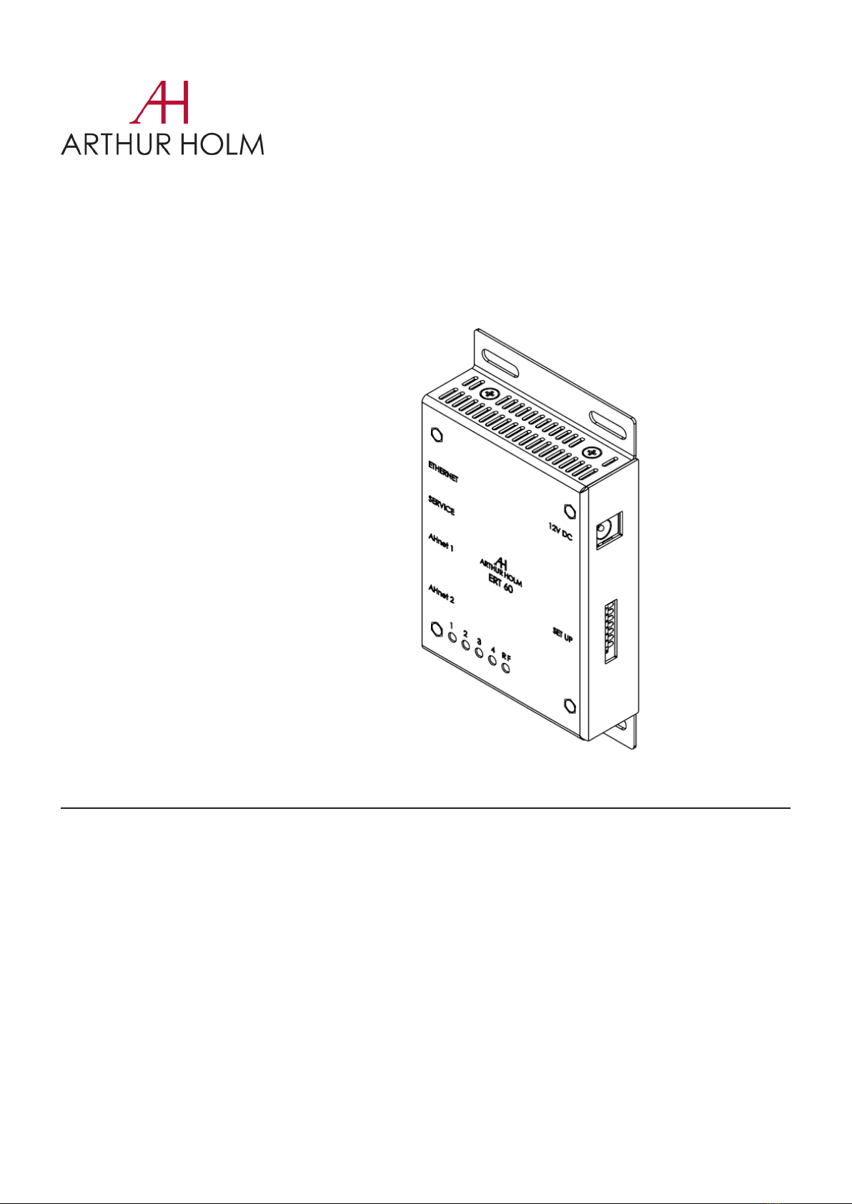
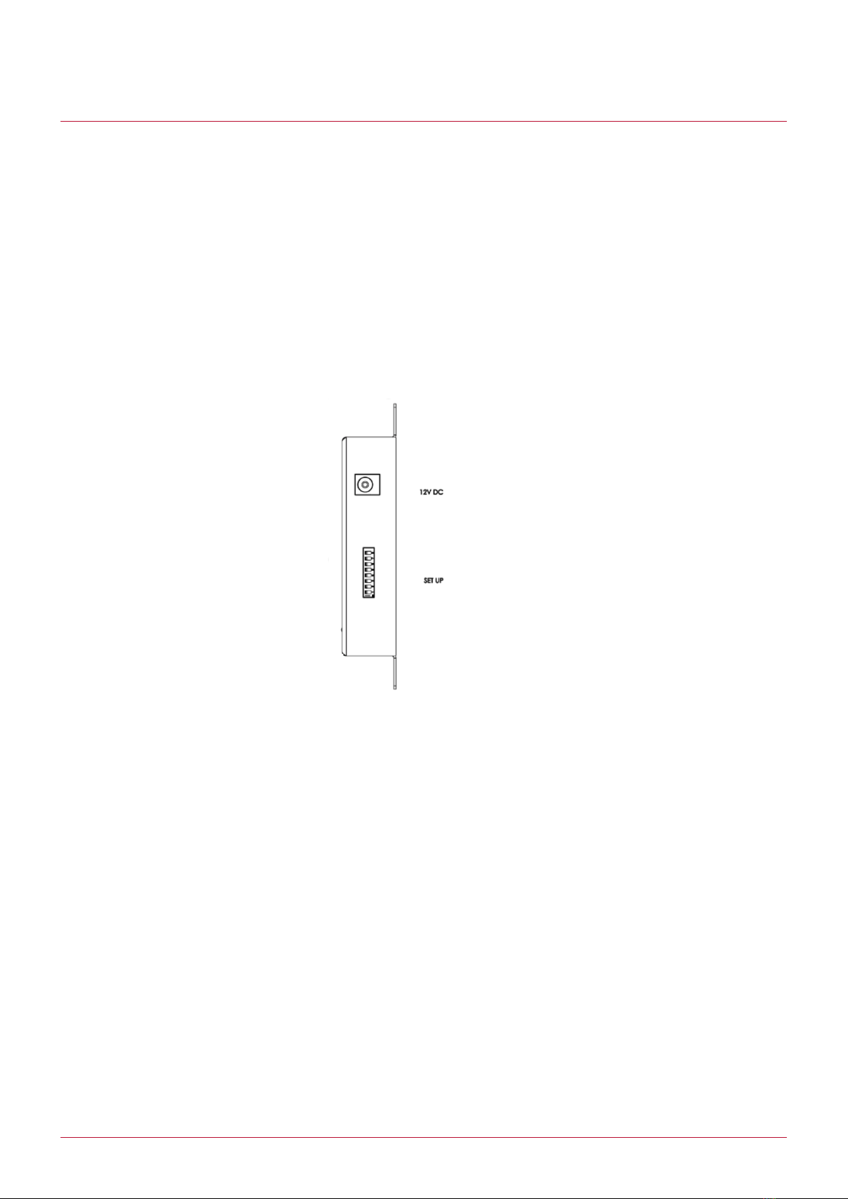
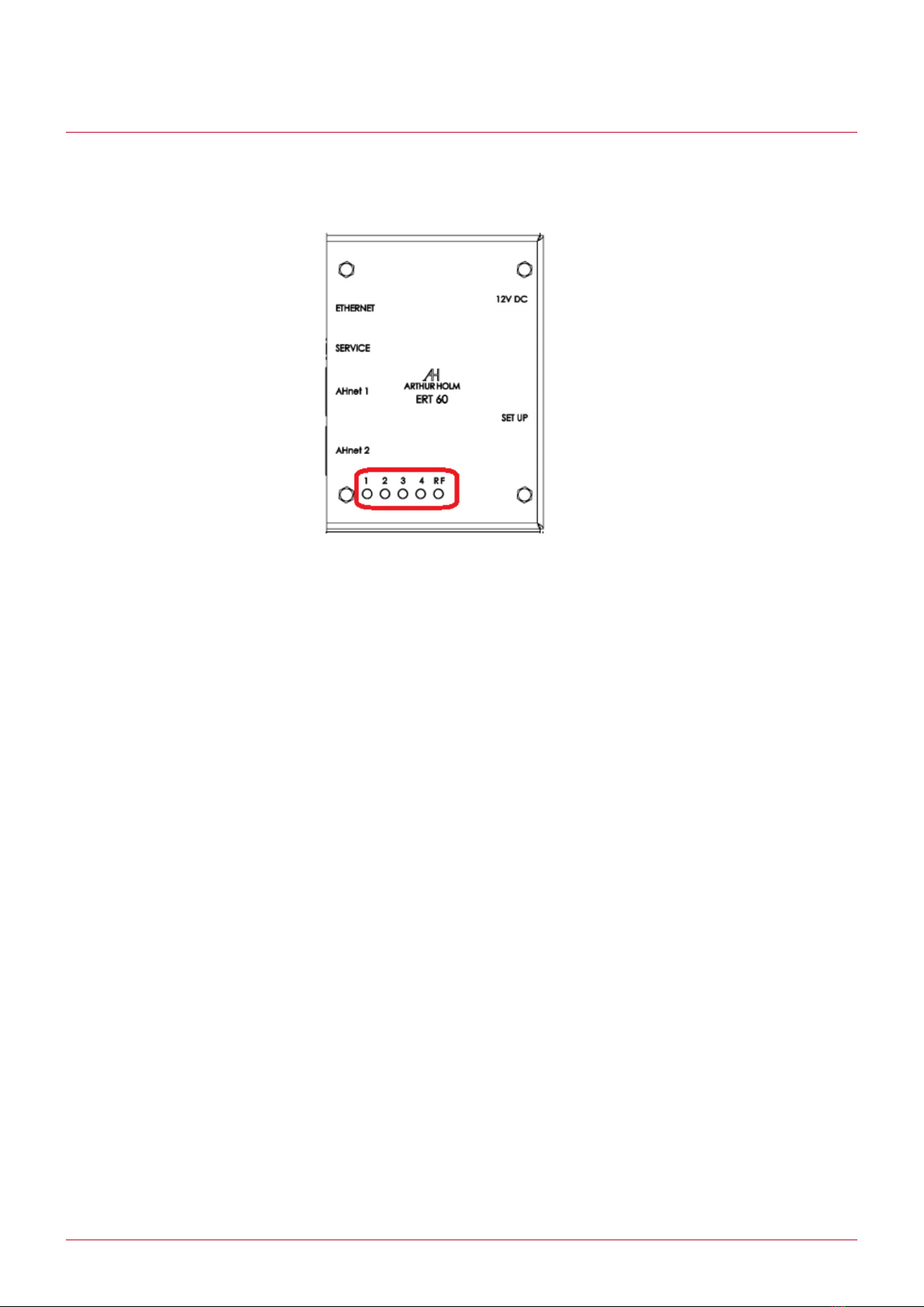
The ERT interface unit, is an Ethernet IP to RS422 interface, in order to use the local network to send AHnet commands to
the Arthur Holm or Albiral units. Just only opening an IP ERT port, the system can send AHnet commands by network, and the
ERT will send the commands to both of the two RS422 RJ45 buses. You can connect up to 60 units in one ERT, using the two
RS422 ports (30 units on each RS422 port)
Note: ERT-30 model has only one AHNet RS422 port. You can control up to 30 units
The ERT interface Unit and AHnet Communication Protocol have been developed to control, configure and diagnose Arthur
Holm units, such as, motorized monitors, motorized microphones, motorized cables, motorized connection box….
System description

8
User manual Box Contents and Start
Before the installation of your ERT unit, please check the contents of the shipping box, it must contain the following items::
›ERt unit
›Power cord
›User manual
›Power supply 100-240Vac, 50-60Hz. Output 12V.
Box Contents
Controls and connectors
12VDC: Power input connector. Plug the power supply supplied
SETUP: Eight deep switches to control and setup the unit
DIP1: Activates the radio signal to control the unit using AHlink APP
DIP2: Activates the automatic AHnet ID configuration on the RS422 bus
DIP3: Not used
DIP4: Activates the firmware upgrade
DIP5: Not used
DIP6: Configures the factory IP address
IP: 192.168.0.128
MASK: 255.255.255.0
GATEWAY: 192.168.0.3
MAC: 70:B3:D5:49:70:00
DIP7: Not used
DIP8: Not used

9
User manual Controls & Connector
ETHERNET: RJ45 network connector. Connect the ERT to your local network, to open the 2002 port and send AHnet com-
mands to the units connected to the RS422 ports (AHnet1 and AHnet2)
SERVICE: USBA connector used only to firmware upgrade
AHnet1: RJ45 RS422 port. Connect the Arthur Holm or Albiral units to control using AHnet commands
AHnet2: RJ45 RS422 port. Connect the Arthur Holm or Albiral units to control using AHnet commands
Note: ERT-30 has only one AHNet RS422 port connector. With and ERT-30 you can control up to 30 devices, and with an ERT-
60, you can control up to 60 devices using the two AHNet port connectors (30 devices connected on each port)
Controls

10
User manual Controls & Connector
LEDs sytem indicators
1. LED1: Change the state when an AHnet command is received from the two RS422 ports (AHnet1 or AHnet2)
2. LED2: Change the state when the unit receives data from the local network port (ETHERNET)
3. LED3: Not used
4. LED4: Change the state when the unit send an AHnet command when the automatic AHnet ID configuration is activated
(DIP2). The ERT interface sends commands to the units connected on AHnet1 and AHnet2 to automatic configure the AHnet
ID on each unit
5. RF: Brigths when a mobile or tablet is connected to the unit to control and configure the ERT using the AHlink APP

11
User manual System Configuration
Use the ETHERNET unit port to connect the ERT to your local network area. Using this port, opens the 2002 ERT IP port, and
send AHnet commands to control the devices connected to RS422 ERT ports (AHnet1 and AHnet2). The Arthur Holm or Albiral
units, has an AHnet IN and AHnet OUT port to easily install a RS422 BUS. Next figure shows a schematic connection diagram.
The main device controller connects to the ERT interface using the local network area. Just opening the 2002 ERT port, the
main device controller can send AHnet commands to the ERT interface, and the ERT sends the AHnet commands to the units
by the RS422 ports.
You can connect up to 60 units to the ERT using the two RS422 RJ45 buses (30 units on each bus). Please, follow the respec-
tive user manual to configure the AHnet address on each unit and to connect the unit to the RS422 bus.
To configure the ERT IP address, do you need to download the AHlink APP. First, do you need to activate the radio signal.
Activate DIP1 on SETTINGS device, and power the ERT unit. To control and configure the unit using AHlink APP, download
“AHLink” from App Store (IOS system) or from Google Play (Android system). The App is free. Execute the “AHLink” on your
mobile phone.

12
User manual System Configuration
On App options, is recommended not select “Auto Connect” and select “Portrait” on “Orientation”. To connect to the device,
selects “Scan for local devices”
The name always begins by “ERT” characters and the fourth last MAC radio address. Select the device to control and configure
the unit

13
User manual System Configuration
Selecting the device, the first page is upload on the mobile phone. This page is used to check the device. When the mobile
APP is connected to the unit the RF LED brights

14
User manual System Configuration
First line, shows the model name of the device
Serial: Serial number of the unit
Ver: Firmware version
Address: Configure the AHnet Address to send the
command. Use address 0 to broadcast the com-
mand instruction
Dynamic2 Control: Send basic commands to Dy-
namic2 monitors family. Select the AHnet address
to send the command, and press the function to
send to AHnet RS422 BUS
Dynamic3 Control: Send basic commands to Dy-
namic3 monitors family. Select the AHnet address
to send the command, and press the function to
send to AHnet RS422 BUS
Dynamic talk Control: Send basic commands to
Dynamic talk microphone family. Select the AHnet
address to send the command, and press the func-
tion to send to AHnet RS422 BUS
IP Address: Shows the actual ERT IP address. Note
that if the DIP6 is active, the unit is configured with
the factory IP and this IP information should be
different
MASK: Shows the actual ERT MAK address
Gateway: Shows the actual ERT gateway address
Configuration PSW: Enter 4006 password to con-
figure the ERT IP address. Next page shows the ERT
network configuration

15
User manual System Configuration
Network configuration: Change the network configuration and press “NETWORK INI” button to update the new network
settings

16
User manual AHnet adress configuration
AHnet adress configuration
There is an ERT functionality that helps the users to configure the AHnet address. To send AHnet commands to a unit, first
do you need to configure the AHnet address to individually send commands. Installing the unit (monitor, microphone or oth-
er device), do you need to configure a different AHnet address on each unit. The ERT has a utility that helps the assignation
of the AHnet address task
First of all, note that this utility it is only available on devices that has LCD screen configuration. The devices that has AHnet
address rotary switches, don’t have this functionality
To activate this function, activate DIP2 on SETTINGS ERT switches, and power the unit. The ERT will periodically send a
special AHnet command to configure the AHnet address on each unit. When the units receive the special AHnet address
configuration command, you hear a BEEP sound. Pressing the UP button on unit cover plate, the unit configures her new
AHnet address. The configuration is incremental. First unit that the user pres the UP button, gets AHnet address 1. Second,
AHnet address 2……..

17
User manual AHnet adress configuration

18
User manual AHnet protocol
AHnet Protocol:
Using 5 bytes to communication:
BYTE 0 is the header and should always FA in HEX mode
BYTE 1 is the unit AHnet address to send the command. To send the command to all the devices, there are special AHnet
address used as broadcast. Please, refer to the user manual unit as there are different family broadcast addresses
BYTE 2 is the function to execute on the unit
BYTE 3 first value of the function
BYTE 4 second value of the function. In some functions this value is not used and should be “00”
Below, there is some AHnet commands used to control the different devices family. You will found more AHnet commands on
the particular user manual

19
User manual AHnet protocol
Dynamic2 family
ZZ Value (0-99Dec)
XX AHnet address
Broadcast XX=F9

20
User manual AHnet protocol
Dynamic 3 family
ZZ Value (0-99Dec)
XX AHnet address
Broadcast XX=F8
Dynamic Talk
XX: AHnet address
Broadcast XX=F7
Other manuals for ERT 30
1
This manual suits for next models
1
Table of contents