6
STANDARD ASSEMBLY NUMBERS / OPTIONS
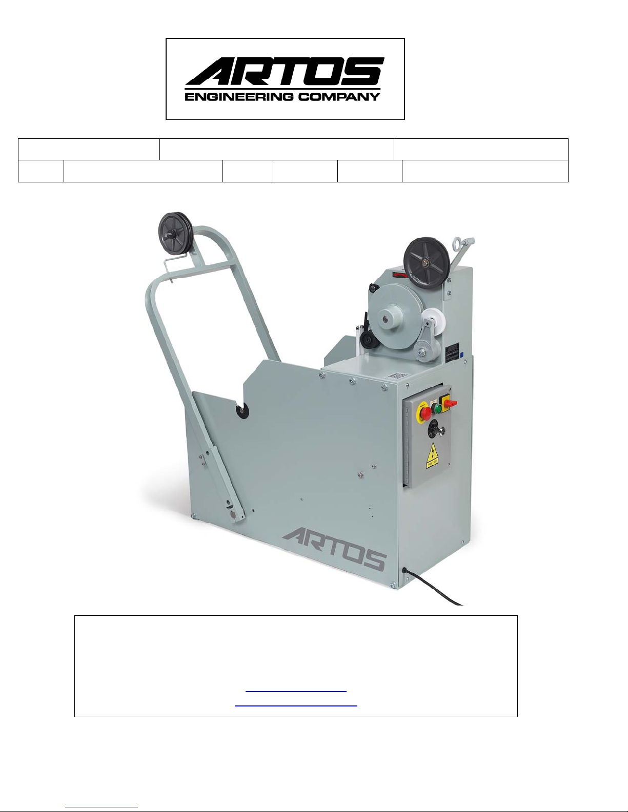
MAINASSEMBLY
2‐134900‐500MainBaseAssembly(Standard)–onthedrawingitlistsvoltageoptions,e‐stopoption,
andbarreladaptorkit.Forthesizingbelowifyoudonotuseaconetocenterspoolontheshaft,the
maximumreelwidthis15.5(394mm).Thesizeoftheshaftis0.625(16mm)diameter.
PULLEYS
2‐134900‐510Aluminumlargewire3pulleyoption.Maximumwirediameteris0.50inches(12.7mm).
2‐134900‐520Plastic3pulleyoption(Standard).Maximumwirediameteris0.38inches(9.6mm).
2‐134900‐530Aluminumlargewire7pulleyoption,forlongwires.Maximumwirediameteris0.50
inches(12.7mm).7pulleysgivesyouaddedwireaccumulation.Thisisusefulwhenyouareprocessing
wiresgreaterthan10feed(3meters)inlength.
2‐134900‐540Plastic9pulleyoption,forlongwires.Maximumwirediameteris0.38inches(9.6mm).9
pulleysgivesyouaddedwireaccumulation.Thisisusefulwhenyouareprocessingwiresgreaterthan10
feed(3meters)inlength.
ROLLERS
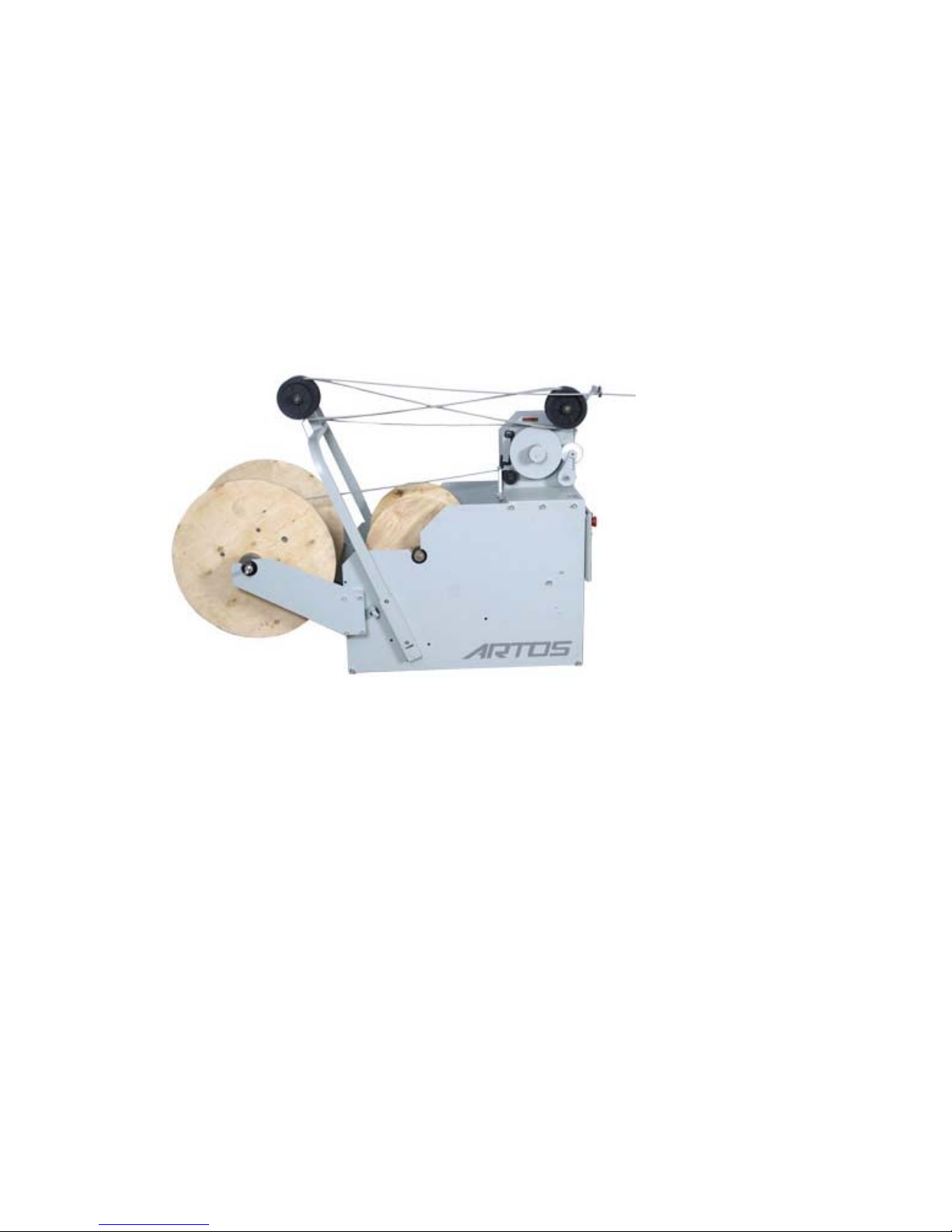
2‐134900‐550Reelsupportrollers.Thisoptionswillallowyousetthespoolintothepre‐feeder,rather
thanputtingashaftthroughthecoreofthespoolandhangingthespoolinthepre‐feeder.Thisoption
requiresthespoolflangestoberoundandundamaged.
POWER/CONTROLOPTIONS
2‐134900‐560110VACpower
2‐134900‐570220VACpower
2‐134900‐610110VACpowerwithovertravelshutdownandmachinefeedback.Thisoptionwill
automaticallyshutdownthepre‐feederwhenthearmispulledallthewayforward.Thiscanhappen
whenthewireistangledandcannotbepulledoffthespool.Aconnectorisprovidedthatwillprovidea
drycontactthatopenswhenthepre‐feederisshutdown.Thisconnectorcanbewiredtoe‐stopthe
wirecuttingmachine.
2‐134900‐600220VACpowerwithovertravelshutdownandmachinefeedback.Thisoptionwill
automaticallyshutdownthepre‐feederwhenthearmispulledallthewayforward.Thiscanhappen
whenthewireistangledandcannotbepulledoffthespool.Aconnectorisprovidedthatwillprovidea
drycontactthatopenswhenthepre‐feederisshutdown.Thisconnectorcanbewiredtoe‐stopthe
wirecuttingmachine.
WIDEREELADAPTIONKITS
5‐144396‐xWidereeladaptionkit.Thisoptionaddsextensionarmstothebackofthepre‐feederso
thatitcanacceptwiderreels.
5‐144396‐1Baseparts.Orderoneoftheseandselectoneoftheitemsfromthelistbelow
Forthesizingbelowifyoudonotuseaconetocenterspoolontheshaft,themaximum
reelwidthis19.5(495mm),Thesizeoftheshaftis0.625(16mm)diameter.