Aruba 9004-LTE User manual

Aruba 9004-LTE Gateway
Installation Guide

www.arubanetworks.com
Hewlett Packard Enterprise Company
Attn: General Counsel
6280 America Center Drive
San Jose, CA 94089
Phone: 408.227.4500
Fax 408.227.4550
Aruba 9004-LTE Gateway | Installation Guide 0512168-01 | April 2020
Copyright
Copyright Information© Copyright 2020 Hewlett Packard Enterprise Development LP.
Open Source Code
This product includes code licensed under the GNU General Public License, the GNU Lesser General Public License,
and/or certain other open source licenses. A complete machine-readable copy of the source code corresponding to
such code is available upon request. This offer is valid to anyone in receipt of this information and shall expire three
years following the date of the final distribution of this product version by Hewlett Packard Enterprise Company. To
obtain such source code, send a check or money order in the amount of US $10.00 to:
Hewlett Packard Enterprise Company
Attn: General Counsel
6280 America Center Drive
San Jose, CA 94089

Aruba 9004-LTE Gateway | Installation Guide Contents | 3
Contents
Contents................................................................................................ 3
Guide Overview......................................................................................................... 5
Related Documentation........................................................................................... 5
Contacting Support .................................................................................................. 5
9004-LTE Gateway ............................................................................... 7
Package Checklist ..................................................................................................... 7
Aruba 9004-LTE Gateway Additional Accessories List ......................................... 8
Aruba 9004-LTE Gateway Components ................................................................. 8
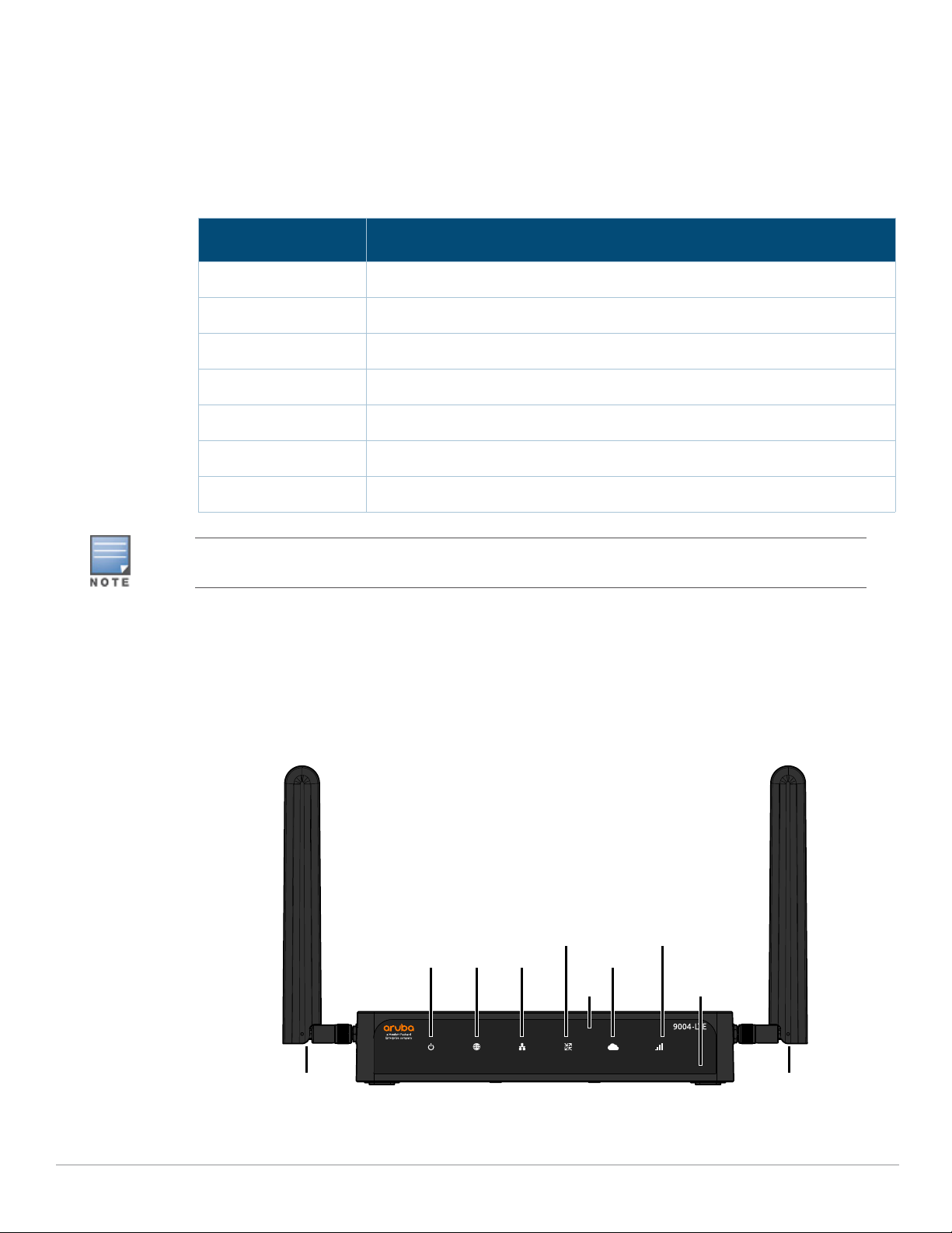
Front Panel LEDs ................................................................................................ 9
DC Power Connector .......................................................................................11
Reset Switch .....................................................................................................11
Ethernet Ports ..................................................................................................11
Micro-USB Console Port..................................................................................12
RJ-45 Console Port ...........................................................................................13
USB Port............................................................................................................13
SIM Tray ............................................................................................................14
Kensington Lock Slot .......................................................................................15
LTE Antennas....................................................................................................15
Installation ......................................................................................... 17
Installation Recommendations.............................................................................17
Precautions..............................................................................................................17
Antenna Mounting Instructions............................................................................18
Cable Saddle Installation Instructions .................................................................19
Desktop Installation Instructions..........................................................................20
Wall Mounting Installation Instructions...............................................................20
Rack Mounting Installation Instructions ..............................................................22
Required Tools and Equipment .....................................................................22
Installation Steps .............................................................................................22
Antenna Extension Instructions............................................................................27
Indoor Antenna Extension Instruction: Aruba 90xx-LTE Indoor Ant Ext Kit-
20ft and Aruba 90xx-LTE Indoor Ant Ext Kit-40ft .........................................27
Outdoor Omni Antenna Extension Instructions: Aruba 90xx-LTE Outdoor
Ant Ext Kit-35ft .................................................................................................32
Specifications, Safety, and Compliance .......................................... 37
Aruba 9004-LTE Gateway Specifications..............................................................37
Physical .............................................................................................................37
Electrical............................................................................................................37
Antenna Connectors........................................................................................37
Environmental..................................................................................................37
Safety and Regulatory Compliance ......................................................................37
FCC Class B Part 15 ..........................................................................................38
EU Regulatory Conformance ..........................................................................39
Wireless Channel Restrictions........................................................................39

4|Contents Aruba 9004-LTE Gateway | Installation Guide
Japan VCCI.........................................................................................................39
Thailand ............................................................................................................40
Regulatory Model Name .................................................................................40
Proper Disposal of Aruba Equipment ..................................................................40
Waste of Electrical and Electronic Equipment..............................................40
India RoHS ........................................................................................................40
China RoHS .......................................................................................................40
Korean...............................................................................................................41
Taiwan ............................................................................................................... 41
Нормативные требования Евразийского Экономического Союза ....42
Mexico ...............................................................................................................42
Brazil..................................................................................................................42

Aruba 9004-LTE Gateway | Installation Guide Preface | 5
Preface
This document describes the hardware features of the Aruba 9004-LTE gateway. It provides a
detailed overview of the physical and performance characteristics of the gateway and explains how
to install the gateway and its accessories.
Guide Overview
Chapter 1, “9004-LTE Gateway” on page 7 provides a detailed hardware overview of the Aruba
9004-LTE gateway and each of its components.
Chapter 2, “Installation” on page 17 describes how to install the Aruba 9004-LTE gateway.
Chapter 3, “Specifications, Safety, and Compliance” on page 37 lists the Aruba 9004-LTE gateway’s
technical specifications and safety and regulatory compliance information.
Related Documentation
The latest ArubaOS User Guide and ArubaOS CLI Reference Guide are required for the complete
management of an Aruba gateway. The latest documentation and the translation of this document
into other languages can be found at www.arubanetworks.com/documentation.
Contacting Support
Table 1 Contact Information
Main Site www.arubanetworks.com
Support Site http://support.arubanetworks.com
Airheads Social Forums and Knowledge Base www.community.arubanetworks.com
North American Telephone 1-800-943-4526 (Toll Free)
1-408-754-1200
International Telephones https://www.arubanetworks.com/support-services/contact-
support/
Software Licensing Site lms.arubanetworks.com
End of Support information www.arubanetworks.com/support-services/end-of-life/end-
of-life-policy/
Security Incident Response Team (SIRT) Site: https://www.arubanetworks.com/support-services/
security-bulletins/
Email: [email protected]

6|Preface Aruba 9004-LTE Gateway | Installation Guide

Aruba 9004-LTE Gateway | Installation Guide 9004-LTE Gateway | 7
Chapter 1
9004-LTE Gateway
The Aruba 9004-LTE gateway is a dual purpose gateway that supports both SD-WAN and wireless LAN
capabilities. The gateway has the ability to directly connect a branch to cloud, provide resilient
connectivity from the cloud, and centralized control for policy management across all branches. The
wireless LAN connects, controls, and intelligently integrates wireless Access Points (APs), Managed
Devices, and Air Monitors (AMs).
The Aruba 9004-LTE gateway has the following port configuration:
Package Checklist
Inform your supplier if there are any incorrect, missing, or damaged parts. To return this product,
repack this unit and other materials included into the original packaging, before returning it to the
supplier.
Table 2 Aruba 9004-LTE Gateway Port Configuration
Model Ports Number of APs
Supported
Number of Users
Supported
9004-
LTE
4 x 10/100/1000BASE-T ports
1 x USB 3.0 port
RJ45 console port
Micro USB console port
32 2048
The Aruba 9004-LTE gateway supports the SD-Wan 2.1.0.0 or later versions.
Table 3 Package Contents
Item Quantity
Aruba 9004-LTE gateway 1
Micro USB console cable 1
Power adapter 1
Adapter cable saddle 1
SIM tray ejector pin 1
LTE antenna 2
Aruba 9004-LTE Gateway Start-up Guide (Printed) 1
Safety, Compliance, and Warranty Information (Printed) 1

8| 9004-LTE Gateway Aruba 9004-LTE Gateway | Installation Guide
Aruba 9004-LTE Gateway Additional Accessories List
Table 4 The Aruba 9004-LTE Gateway also has additional accessories provided for replacing
damaged equipments or extending the device functionalities. The list of Aruba accessories kit
compatible with the Aruba 9004-LTE Gateway are mentioned below:
Table 5 Additional Accessory Kits
Aruba 9004-LTE Gateway Components
This section introduces the different component and its location in the Aruba 9004-LTE gateway.
Figure 1 shows the front panel of the Aruba 9004-LTE gateway and Figure 2 shows the back panel
of the Aruba 9004-LTE gateway.
Figure 1 Front Panel of the Aruba 9004-LTE gateway
* The antenna is integrated within the hardware and is not displayed on the front panel.
Part Number Accessory Kit Name
R3W17A Aruba 9004-LTE-MNT-19 Rack Mount Kit
R4Y91A Aruba 90xx-LTE Indoor Ant Ext Kit-20ft
R4Y92A Aruba 90xx-LTE Indoor Ant Ext Kit-40ft
R4Y93A Aruba 90xx-LTE Outdoor Ant Ext Kit-35ft
R4Y94A Aruba 90xx-LTE Spare Indoor Antenna
R4Y95A Aruba 90xx-LTE Spare SIM Tray Kit
R6M37A Aruba 90xx-LTE Spare Outdoor Antenna
Optional accessories available for use with the Aruba 9004-LTE gateway are sold separately. Contact your
Aruba sales representative for details and assistance.
System WAN LAN
GW Mode
Central/Cloud
NFC
Antenna*
BLE
Antenna*
Cellular
LTE Antenna LTE Antenna

Aruba 9004-LTE Gateway | Installation Guide 9004-LTE Gateway | 9
Figure 2 Back Panel of the Aruba 9004-LTE Gateway
Figure 3 Right Side View of the Aruba 9004-LTE Gateway
Figure 4 Left Side View of the Aruba 9004-LTE Gateway
Front Panel LEDs
The front panel LEDs show the System, WAN, and LAN status including various other features.
These front panel LEDs provide basic monitoring information of the overall status of the Aruba
DC Power
Connector
Reset
Switch
Ethernet
Ports
Micro USB
Console Port
Console
Port
Kensington
Lock Slot
USB
Port
Sim
Tray
GPS Antenna
Connector
Diversity Antenna
Connector
Main Antenna
Connector

10 | 9004-LTE Gateway Aruba 9004-LTE Gateway | Installation Guide
9004-LTE gateway. The following table describes the LED indicators and their corresponding
status:
Table 6 LED Status
LED Function Indicator Status
System System status Green (Solid) Powered and Operational
Green (Blinking) Loading Software
Amber (Solid) Critical Alarm
Amber (Blinking) Major Alarm
Off Power Off
WAN WAN Connectivity
Status
Green (Solid) All WAN Ports Established
Green (Blinking) Transmitting or Receiving Traffic
Amber (Solid) No WAN Ports Established
Amber (Blinking) One or More WAN Ports Not
Established
LAN Link Status Green (Solid) One or More LAN Ports Established
Amber (Solid) No LAN Ports Established
GW Mode WLAN Gateway
mode / SDWAN
Gateway mode
Green (Solid) The WLAN / SD-WAN Gateway is Up
and Functioning
Green (Blinking) The WLAN / SD-WAN Gateway is
Booting
Central/Cloud Central
Connectivity
Status
Blue (Solid) Connected to Central
Blue (Blinking) Connecting to Central

Aruba 9004-LTE Gateway | Installation Guide 9004-LTE Gateway | 11
DC Power Connector
The AC-DC adapter kit with the following specification is used to power the Aruba 9004-LTE
gateway:
12V/2.5A power interface
Center-positive 2.1/5.5 mm circular plug, 9.5 mm length
Reset Switch
The Aruba 9004-LTE gateway includes a recessed button for resetting the gateway configurations.
Insert a pin into the Reset Switch hole until you feel the pin touch a surface. Push and hold the pin
for two seconds to reset the gateway configuration.
Ethernet Ports
The Aruba 9004-LTE gateway is equipped with four 10/100/1000BASE-T Gigabit Ethernet ports (0
to 3). Gigabit Ethernet uses all eight wires and each pair is bidirectional, which means, the same
pair is used for both data transmission and reception. Figure 5 illustrates the Gigabit Ethernet
port pin-out for an RJ-45 connector. The pins paired on a 10/100/1000Base-T Gigabit Ethernet
port are: 1/2, 3/6, 4/5, and 7/8.
Cellular Link Status
NOTE: The link
status is applicable
to cellular uplink
and is independent
of the hardware,
that is, either the
internal LTE
module or the
external LTE
dongle.
Green (Solid) Modem Initialized and Connected to
the Network. Good Signal Strength.
Signal Strength Threshold:
> -65 dBm
Green (Blinking) Modem Initializing
Green + Amber (Greenish
Yellow) (Solid)
Modem Initialized and Connected to
the Network. Average Signal Strength.
Signal Strength Threshold:
< -65 dBm
> -80 dBm
Amber (Solid) Modem Initialized and Connected to
the Network. Poor Signal Strength.
Signal Strength Threshold:
< -80 dBm
Amber (Blinking) Network Connection Failure. SIM
Removal. Modem not Responding to
Web Commands.
Red (Solid) Modem Lost IP Address or
Disconnected from the Network.
Acting as a Backup Uplink.
Red (Blinking) Hardware Failure. USB Failure.
Unsupported USB Device Attached.
Table 6 LED Status
LED Function Indicator Status

12 | 9004-LTE Gateway Aruba 9004-LTE Gateway | Installation Guide
Figure 5 Figure 3 Gigabit Ethernet Port Pin-Out
Ethernet Port LEDs
Each 10/100/1000BASE-T Ethernet port is equipped with two LEDs that allow basic monitoring of
link/act and status activities.
LINK/ACT: Placed on the left side of the port, and displays the link status and activity of the
port.
STATUS: Placed on the right side of the port, and displays the status of the port based on the
CLI.
The following table describes the LED behavior for each mode:
Micro-USB Console Port
The Aruba 9004-LTE gateway is equipped with a Micro-USB (type B) connector that provides
direct local console access. If both Micro-USB and RJ-45 console ports are connected, the Micro-
USB connection takes precedence over the RJ-45 console connection.
Micro-USB Driver
To use the Micro-USB console port, you must install the Aruba Micro-USB driver on the computer
that will manage your gateway. To download the driver, perform the following steps:
1. Go to https://support.arubanetworks.com.
2. Click on the Tools & Resources tab.
3. Open the USB Console Driver folder.
4. Open the Mobility Gateway and Mobility Access Switch folder.
Select the appropriate file for your application. The corresponding operating system is in the file
name.
Table 7 10/100/1000BASE-T Ethernet Port LEDs
LED Function Mode Indicator Status
LINK/ACT Link status NA Green (Solid) Link established
Green (Blinking) Port is transmitting or receiving
data
Off No link
STATUS Port status Speed Green (Solid) Link at 1000 Mbps
Off Link at 10/100 Mbps
1000Base-T Gigabit
Ethernet Port
RJ-45 Female
Pin-Out
Signal Name
1
2
3
4
5
6
7
8
BI_DC+
BI_DC-
BI_DD+
BI_DD-
BI_DA+
BI_DA-
BI_DB+
BI_DB-
Function
Bi-directional pair +C
Bi-directional pair -C
Bi-directional pair +D
Bi-directional pair -D
Bi-directional pair +A
Bi-directional pair -A
Bi-directional pair +B
Bi-directional pair -B

Aruba 9004-LTE Gateway | Installation Guide 9004-LTE Gateway | 13
RJ-45 Console Port
The serial console port allows connecting a gateway to a serial terminal or a laptop for direct local
management. This port is a RJ-45 female connector with the pin-outs descried in Figure 6.
Connect it directly to a terminal or terminal server using an Ethernet cable.
Figure 6 Serial Console Port Pin-Out
The communication settings for the RJ-45 console port is shown in the following table:
Serial Console Port Adapter
A modular adapter can be used to convert the female RJ-45 connector to a male DB9 connector.
See Figure 7 for complete details.
Figure 7 RJ-45 (Female) to DB9 (Male) Modular Adapter Conversion
USB Port
The Aruba 9004-LTE gateway is equipped with one USB 3.0 interfaces. A USB storage device can
be used to save and upload configurations to the gateway.
The Aruba 9004-LTE gateway also provides support for USB LTE Modems.
If the Aruba 9004-LTE gateway has an active SIM card installed in the SIM card slot during boot
up, then gateway does not initialize the external modem (even if the external modem is inserted
before booting up the device). In cases where the internal LTE module fails to connect due to the
Table 8 RJ-45 Console Terminal Settings
Baud Rate Data Bits Parity Stop Bits Flow Control
9600 8 None 1 None
Serial
Console Port
1
2
3
4
5
6
7
8
TxD
GND
RxD
RJ-45 Female
Pin-Out
Direction
Input
Output
GND
The RJ-45 CONSOLE port is compatible only with RS-232 devices. Non-RS-232 devices, such as APs, are not
supported.
Do not connect the RJ-45 Console port to an Ethernet switch or a PoE power source. This may damage the
gateway.
3
4
5
2
5
63
RJ-45 DB-9
Internal
Connections
TxD
GND
RxD
1
2
3
4
5
6
7
8
TxD
GND
RxD
RJ-45 Female
Pin-Out
DB-9 Male
Pin-Out
TxD
RxD
Ground
5
4
3
2
1
9
8
7
6

Aruba 9004-LTE Gateway | Installation Guide 9004-LTE Gateway | 14
absence of an active SIM, or any other reasons, then the gateway boots up with the external
modem connectivity since the external modem is already connected to the gateway before boot
up.
However, if the device is already powered on and the external modem is plugged in to the USB
slot runtime, the external modem does not work and requires the device to reboot to become
functional.
SIM Tray
The 9004-LTE gateway is equipped with a dual nano-SIM tray. At any given time, only one SIM
card is active and functional, the SIM 1 and SIM 2 can not be used simultaneously.
To install a SIM card into the SIM tray, perform the following steps:
1. Insert the SIM ejector needle (provided with package contents) into the small hole on the SIM
Tray. The card tray will pop open. See Figure 8.
Figure 8 Opening a SIM Card Tray
2. Pull out the SIM card tray and insert a SIM card, gold contact facing downwards, into the SIM
tray.
3. Push the SIM tray back into the slot. See Figure 9.
1
2

Aruba 9004-LTE Gateway | Installation Guide 9004-LTE Gateway | 15
Figure 9 Inserting a SIM Card
Kensington Lock Slot
The Aruba 9004-LTE gateway is equipped with a Kensington security slot for additional security.
LTE Antennas
The Aruba 9004-LTE gateway is equipped with 3 antenna options, see Figure 3 and Figure 4. The
options include:
MAIN: Main LTE Antenna
DIV: Diversity LTE Antenna
GPS: GPS Antenna
1
2
Slot 2
Slot 1
In case the SIM tray gets damaged or disfunctional, you can order a spare SIM tray available for use with
the Aruba 9004-LTE gateway. The spare SIM tray is sold separately. Contact your Aruba sales
representative for details and assistance.
Table 9 LTE Antenna Types and Functionality
Antenna Type Description Mode
Main Supports:
1 x TX
1 x RX
Works independently as a 1x1 SISO even if Diversity
antenna is not connected.
LTE
Diversity Supports:
1 x RX
NOTE: Does not work independently when the Main antenna is
not connected.
LTE

16 | 9004-LTE Gateway Aruba 9004-LTE Gateway | Installation Guide
GPS Supports:
1 x RX
Works independently even if Main or Diversity antennas
are not connected.
NOTE: Ensure that the GPS antenna is placed in an open space
with clear access to the sky, or ensure that the device is placed
closer to the window for the GPS functionality to work properly.
GPS
Table 9 LTE Antenna Types and Functionality
Antenna Type Description Mode
The GPS antenna is not included in the package. It is an additional accessory that can be ordered
separately. Both, Aruba 90xx-LTE Spare Indoor Antenna and the Aruba 90xx-LTE Spare Outdoor Antenna
can be used as GPS antennas along with the three extender kits available for 9004-LTE gateways. Refer on
page 8 for the types of extender kits. Contact your Aruba sales representative for details and assistance.

Aruba 9004-LTE Gateway | Installation Guide Installation | 17
Chapter 2
Installation
This chapter describes how to install the indoor LTE antennas on the Aruba 9004-LTE gateway.
You can mount the Aruba 9004-LTE gateway on any flat surface such as a desktop, or a shelf. Or you
can mount the gateway in a standard, 19-inch telco rack or on a wall using the various accessory kit
(not included in box) provided by Aruba.
This section also provides details of extending the antenna placements using the antenna extender
kits (additional accessories), or place the antennas outdoor using the Outdoor Omni antenna along
with the extender kit (additional accessory).
Installation Recommendations
For proper air circulation, leave at least 10 cm (4 inches) clearance on the left, right, front, and rear
side of the gateway.
Leave additional space in front and rear side of the gateway to access power cords, network
cables, and indicator LEDs.
Avoid placing anything on top of the gateway as it can lead to overheating of the gateway.
Avoid placing this gateway on any other device as the heat dissipated from the other device can
over heat the gateway.
Ensure that the rack is correctly and securely installed to prevent it from falling or becoming
unstable.
Precautions
Dangerous voltage above 240 V AC is always present while the Aruba Power Supply Module is
plugged into an electrical outlet. Remove all rings, jewelry, and other potentially conductive
material before working with this device.
Never insert foreign objects into the chassis, power supply, or any other component, even when
the power supply is turned off, unplugged, or removed.
Ensure that the main power is fully disconnected from the gateway by unplugging all power cords
from their outlets. For safety, verify that the power outlets and plugs are easily reachable by the
operator.
Do not handle electrical cables which are not insulated. This also includes network cables.
Keep water and other fluids away from the gateway to minimize electrical hazards.
Comply with electrical grounding standards during all phases of installation and operation of the
product. Do not allow the gateway’s chassis, network ports, power supply, or mounting brackets
to contact any device, cable, object, or person attached to a different electrical ground. Also, never
connect the device to external storm grounding sources.
Perform installation or removal of the chassis or any module in a static-free environment. Proper
use of anti-static body straps and mats is strongly recommended.
Modules must be kept in anti-static packaging when not installed in the chassis.
Do not ship or store this product near strong electromagnetic, electrostatic, magnetic, or
radioactive fields.
Installation of the device should be performed by a trained installation professional.

18 |Installation Aruba 9004-LTE Gateway | Installation Guide
This product, power cords, and all interconnected cables are for indoor use only.
Antenna Mounting Instructions
The Aruba 9004-LTE gateway supports 3 antenna options, Main, Diversity, and GPS. Each of these
antennas can be either connected directly to the device, or can be connected using extension cables
(additional accessories, not provided in the package) for proper placement.
To install a Main or Diversity antenna on an Aruba 9004-LTE gateway, perform the following steps:
1. Remove the protection caps from MAIN and DIV antenna connector. See Figure 10.
Figure 10 Removing MAIN and DIV Antenna Connector Caps
2. Align the LTE antenna connector with the connector provided on the device.
3. Secure the LTE antenna by screwing it tightly to the connectors on the device. See Figure 11 and
Figure 12.
Figure 11 Connecting External Antennas

Aruba 9004-LTE Gateway | Installation Guide Installation | 19
Figure 12 Connecting External Antenna
Your LTE antenna installation is now complete.
Cable Saddle Installation Instructions
The Aruba 9004-LTE gateway provides the option of attaching a cable saddle to the device to secure
the power cable with the device.
To attach a cable saddle to the 9004-LTE gateway, perform the following steps:
1. Align the cable saddle with the slot on the side of the gateway and push the cable saddle into the
unit to secure it. See Figure 13.
Figure 13 Attaching a Cable Saddle
2. Insert the cable into the cable saddle and attach it to the power connector slot. This secures the
cable and keeps it in place.See Figure 14.

20 |Installation Aruba 9004-LTE Gateway | Installation Guide
Figure 14 Securing a Cable
Your cable saddle installation in now complete.
Desktop Installation Instructions
The Aruba 9004-LTE gateway can be kept on a desktop or any flat surface after the antenna and cable
saddle installations are done. Just place the device on an open surface with the antennas pointing
upright. See Figure 15.
Figure 15 Desktop Mounting
Wall Mounting Installation Instructions
The keyhole-shaped slots on the bottom of the gateway can be used to attach the device upright
(back port facing downwards) to an indoor wall or shelf. Make sure to mount the gateway in such a
way that there is a clear path to the Ethernet port, such as a predrilled hole in the mounting surface
to pass the wire.
To mount the 9004-LTE gateway to a wall, perform the following steps:
Table of contents
Other Aruba Gateway manuals
Popular Gateway manuals by other brands

AddPac
AddPac VoiceFinder AP1100 installation guide

Flexitron
Flexitron WebdynPulse WG0510-A01 manual

Grandstream Networks
Grandstream Networks GXW4232 manual

Moxa Technologies
Moxa Technologies OnCell G3470A-LTE User manuals

Aaeon
Aaeon AIOT-IP6801 user manual

Media5
Media5 Mediatrix C710 Hardware installation guide