ARVOO ITS101 User manual

Installation Manual
ITS101
Preliminary version
Company confidential

ITS101 Installation Manual
ARVOO Imaging Products B.V.
P.O. Box 439
3440 A Woerden
The Netherlands
Tel +31-348-413 897
Fax +31-348-417 242
website: http://www.arvoo.com
general e-mail: [email protected]
support e-mail: [email protected]
Copyright © 2012 ARVOO Imaging Products B.V.
Version: 1.08
Date: October 2012
All rights reserved. No part of this publication may be reproduced, stored in a retrieval system,
or transmitted, in any form by means, electronic, mechanical, by photocopying, recording, or
otherwise, without the prior written permission of ARVOO.
Information furnished by ARVOO is believed to be accurate and reliable; however, no
responsibility is assumed by ARVOO for its use; nor for any infringements of patents or other
rights of third parties which may result from its use. No license is granted by implication or
otherwise under any patent rights of ARVOO.
Intrada is a registered trademark of Dacolian BV.
The term "Linux" is a registered trademark of Linus Torvalds.
WindowsTM is a registered trademark of Microsoft Corporation.
ARVOO Imaging Products B.V. page 2 of 33

ITS101 Installation Manual
Contents
1. Introduction...............................................................................................................4
2. Cabling......................................................................................................................5
2.1. Power..................................................................................................................5
2.2. RELAY.................................................................................................................6
2.3. RS-232................................................................................................................7
2.4. GPIO...................................................................................................................8
2.4.1. I/O settings....................................................................................................9
2.5. Ethernet..............................................................................................................9
2.6. ANPR Digital Interface.........................................................................................10
2.7. ANPR CVBS Input................................................................................................10
2.8. Video Output CVBS..............................................................................................11
2.9. USB...................................................................................................................11
3. Network configuration...............................................................................................12
3.1. Back to default factory settings.............................................................................12
3.2. Ethernet.............................................................................................................13
3.3. OpenVPN............................................................................................................14
3.3.1. Setting up an OpenVPN server........................................................................16
3.4. Time settings......................................................................................................19
4. ANPR camera...........................................................................................................20
4.1. ITS101-CAM, ARVOO digital ANPR camera .............................................................20
4.1.1. ANPR camera settings....................................................................................20
4.2. Analog ANPR camera...........................................................................................21
5. Firmware application configuration, installation and upgrading.......................................22
5.1. Application configuration......................................................................................22
5.2. Firmware installation...........................................................................................23
6. Technical specifications..............................................................................................26
6.1. Electrical specifications........................................................................................26
6.2. Environmental specifications.................................................................................28
6.3. Mechanical specifications......................................................................................28
7. Troubleshooting........................................................................................................30
7.1. LEDs..................................................................................................................30
7.2. Communication problems.....................................................................................30
7.2.1. Firewall........................................................................................................30
7.2.2. OpenVPN......................................................................................................31
7.3. ANPR problems...................................................................................................31
7.3.1. Dirty camera.................................................................................................31
7.3.2. Incorrect camera placement............................................................................31
7.3.3. Dirty number plates.......................................................................................32
7.3.4. Stop and go violation.....................................................................................32
7.3.5. Latency........................................................................................................32
7.4. Further support...................................................................................................32
7.4.1. Host information sources................................................................................32
8. Appendices..............................................................................................................33
8.1. Glossary.............................................................................................................33
ARVOO Imaging Products B.V. page 3 of 33

ITS101 Installation Manual
1. Introduction
This document describes how the ITS101 has to be installed and configured.
The ITS101 is an automated number plate recognition system for access control applications.
The end user is provided with usable license plate recognition data. The unit handles a number
of I/O's – for instance based on license plate black/white listing – for access control purposes.
The front end of the ITS101 consists of an ANPR camera. ANPR cameras differ from normal
CCTV cameras in that they are specifically designed to capture good, clear images of infrared-
reflective license plates in all weather conditions, day or night. In most conditions only the
license plate will be visible when using an ANPR camera, only on very sunny days other
elements of the surroundings will be visible. The ANPR camera can either be an analog camera
or an ARVOO digital camera.
The images from the ANPR camera are processed using the Intrada ANPR software that is
embedded onto the processing board. Images from the ANPR camera are scanned for license
plates and then optical character recognition algorithms are applied. The end product is license
plate recognition data in the form of a text string, packed in an XML protocol. Together with
this the board handles a number of I/O's for access control purposes.
The ITS101 is meant to be used for stop and go situations. This means that the vehicle must
come to a stand-still in order to give the ITS101 sufficient time to read the license plate.
The ITS101 is running a web service that can be accessed via a standard web browser. This
allows to configure the network, retrieve diagnostic information and perform firmware control.
ARVOO Imaging Products B.V. page 4 of 33

ITS101 Installation Manual
2. Cabling
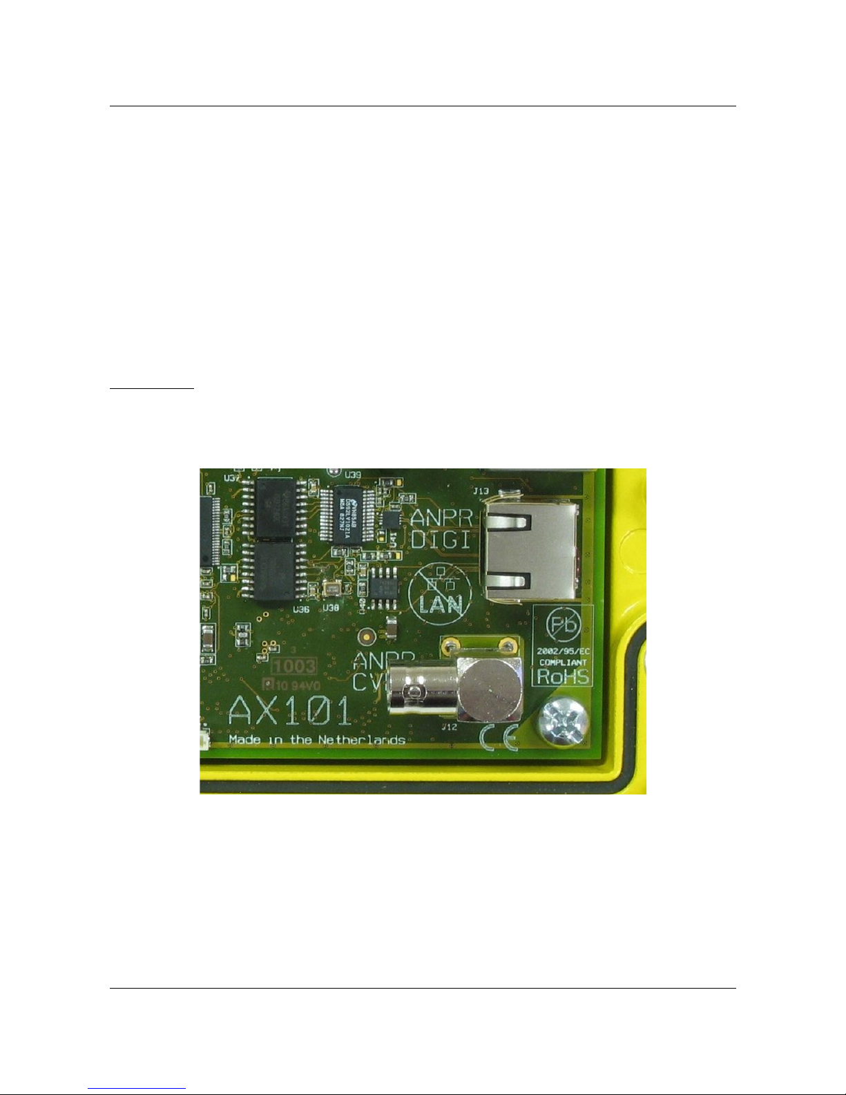
See below for an overview picture of the ITS101, which shows all interfaces and their
connectors.
This section describes the cabling of the unit. Before making any connections to the ITS101
make sure it is turned off.
The following interfaces/connections make use of green 45º screw terminal blocks:
–POWER
–RELAY
–RS-232
–GPIO
These 45º screw terminal blocks can be used for wires up to 1.3 mm² and have the following
specifications:
–Wire: 28-16AWG / 0.08-1.3 mm²
–Rising Cage Clamp
–Wire strip length: 5-6 mm
–Screw: M2, torque 0.2 Nm
–Pitch: 3.5 mm
2.1. Power
The ITS101's internal power supply is rated for an input voltage of +10 V to +14 V DC.
The recommended rating of an external 12 V DC power supply is 1.5 A (18 W).
ARVOO Imaging Products B.V. page 5 of 33
Figure 1: ITS101 PCB overview with all interface connectors

ITS101 Installation Manual
The pin-out of the 3-pin Power connector (J11) is given in next table.
Pin (left to right) Name PCB Signal
1 + +10 .. +14 V DC
2 - GND
3 Chassis_GND (EARTH)
Table 1: Power connector
2.2. RELAY
The ITS101 has two small signal relay outputs. These relays are not eant for direct
switching of 110 or 220 V AC applications or high currents. They can be used to signal
the control-unit of a barrier or an outdoor 24 V DC signal-LED.
The pin-out of the 6-pin Relay connector (J10) is given in next table. See Figure 2 for a
detailed PCB picture of this relay connector (name on the PCB rev. A is by mistake RELAIS).
ARVOO Imaging Products B.V. page 6 of 33
Figure 2: Detail of the POWER and RELAY connectors Also the
hardware reset switch is visible at the upper-right corner

ITS101 Installation Manual
Pin (left to right) Name PCB Signal
1 RL1_NC Relay 1, Normally Closed
2 RL1_COM Relay 1, Common
3 RL1_NO Relay 1, Normally Open
4 RL2_NC Relay 2, Normally Closed
5 RL2_COM Relay 2, Common
6 RL2_NO Relay 2, Normally Open
Table 2: Relay connector pin-out
2.3. RS-232
An RS-232 port is optionally in use by the ANPR application. We refer to documentation of the
ANPR application.
The pin-out of the 6-pin RS-232 connector (J6) is given in next table.
Pin (left to right) Name PCB Signal
1 TX1 Transmit port 1
2 RX1 Receive port 1
3 GND GND
4 TX2 Transmit port 2
5 RX2 Receive port 2
6 GND GND
Table 3: RS-232 connector pin-out
ARVOO Imaging Products B.V. page 7 of 33

ITS101 Installation Manual
2.4. GPIO
For detailed input and output specifications, see Chapter 6 Technical specifications.
The pin-out of the 6-pin GPIO connector (J4) is given in next table. See Figure 3 for a detailed
PCB picture of this GPIO connector.
Pin (left to right) Name PCB Signal
1 IN_0 Input 1. Slow input signals can
be seen on front by means of
LED-indication. Range: 5-12 V.
2 IN_1 Input 2. Slow input signals can
be seen on front by means of
LED-indication. Range: 5-12 V.
3 IN_COM Common for the inputs.
4 OUT_0 Output 1.
5 OUT_1 Output 2.
6 OUT_COM Common for the outputs.
Table 4: GPIO connector pin-out.
ARVOO Imaging Products B.V. page 8 of 33
Figure 3: Detail RS-232, GPIO and LAN connectors

ITS101 Installation Manual
2.4.1. I/O settings
Navigate to the I/O settings page of the web service for configuring the I/O behavior.
Explanation:
•The upper line can be used to add actions to events. For a list of possible events and
actions see below.
•Lines below the bold header are actions which are currently active. When the “del “
button is pushed the action line is removed.
Note: Actions are performed independent from each other. This means that when an output is
set high on one line, but set low on another line, the behavior is unknown.
Events:
•EVENT_LP: a license plate is recognized, either on list or not on list
•EVENT_LP_ONLIST: a license plate is recognized, with a hit on the black/white list
•EVENT_LP_NOT_ONLIST: a license plate is recognized, with no hit on the black/white
list
Actions:
•ACTION_OUT1_HI: set output 1 high
•ACTION_OUT1_LO: set output 1 lo
•ACTION_OUT2_HI: set output 2 high
•ACTION_OUT2_LO: set output 2 lo
•ACTION_RELAY1_HI: set relay 1 high
•ACTION_RELAY1_LO: set relay 1 lo
•ACTION_RELAY2_HI: set relay 2 high
•ACTION_RELAY2_LO: set relay 2 lo
See section 5.1 for on how to use GP input 0 or 1 for triggering the recognition
algorith .
2.5. Ethernet
The ITS101 is provided with an RJ-45 connector. A standard Cat5e patch cable will be
adequate for connection of the unit to a stand-alone computer or to a local area network.
ARVOO Imaging Products B.V. page 9 of 33
Figure 4: Screenshot I/O settings page
ITS101 Installation Manual
See Figure 3 for a detailed PCB picture of this LAN connector. Also visible is the sticker with the
MAC-address for this specific unit.
2.6. ANPR Digital Interface
The ITS101 is provided with an ARVOO proprietary ANPR Digital Interface, for a direct
connection to the ARVOO ITS101-CAM digital camera. The default cable length with this
camera is 10 meters, this is also the maximum cable distance. Power for the camera is
supplied by the ITS101.
When you select the ANPR Digital Interface the ANPR CVBS interface (Analog video input, PAL/
NTSC) is not in use. The ANPR Digital Interface can be selected by selecting the proper
firmware. See chapter 5. for more information regarding firmware installation.
This interface makes also use of an RJ-45 connector.
Precaution: This interface is not compatible with any Ethernet standard. Connecting a patch
cable to an Ethernet switch will destroy the switch or the ITS101. Before connecting
the ITS101-CAM make sure the power to the ITS101 is turned off. The ITS101-CAM is not
hot pluggable.
2.7. ANPR CVBS Input
The ANPR CVBS input is a female BNC connector. This analog video input can accept any
standard PAL/NTSC camera. You can select the use of the ANPR CVBS input by activating the
proper firmware. The ANPR Digital Interface is turned off in this case. See chapter 5. for more
information regarding firmware installation.
ARVOO Imaging Products B.V. page 10 of 33
Figure 5: Detail of ANPR Digital and CVBS inputs

ITS101 Installation Manual
See Figure 5 for the connector position on the ITS101 PCB.
2.8. Video Output CVBS
The 'VIDEO OUTPUT' connector is meant for service purposes. A combination of the life view
and the latest image with license plate result is displayed via this video output.
2.9. USB
The USB interface is only for use by ARVOO.
ARVOO Imaging Products B.V. page 11 of 33
Figure 6: Detail USB and Video Output CVBS

ITS101 Installation Manual
3. Network configuration
Note: The name AX101 appears on the configuration pages and log messages It can be seen
as an equivalent for ITS101
The ITS101 has Ethernet as general communication interface. This gives LAN (local area
network) access to the unit. If required, access to the unit can be secured via a VPN (virtual
private network) layer running on top of the LAN. For this, correct time settings are required.
As the network is configured via a web browser, a factory network setting is required. The unit
has a factory set static IP address of 192.168.0.240. If this conflicts with the network via
which the web browser tries to access the unit, connect to the unit directly via a crossover
cable.
The web service entrance page can be retrieved via a standard web browser using the address
HTTP://192.168.0.240. The pages 'lan settings', 'openvpn settings' and 'ntp/time settings' are
for configuring the network. These settings are explained in this chapter. The pages 'System
information', 'System log', 'Appl log', 'Dsp log' are for support purposes. These are explained in
section 7.4.1.
The username to use is 'admin', the default password consists of the last 4 digits of the unit's
MAC address in capital letters. This password can be changed via the 'change password' page.
When setting are unknown and you are unable to connect to the ITS101, default factory
settings can be restored by the procedure described in section 3.1.
Precaution: the network is configured via the web service that uses the network. Be aware
not to switch off the Ethernet communication.
3.1. Back to default factory settings
When default network settings need to be restored, because you are not able to access the
unit anymore, the following procedure needs to be followed.
ARVOO Imaging Products B.V. page 12 of 33
Figure 7: Back to Default switch

ITS101 Installation Manual
Power-up the ITS101 unit and wait until the red LED DS12 is flashing fast. At that moment you
have 4 seconds to press the Back to Default switch. LED DS12 is mounted at the right side of
connector J6 at the upper side of the PCB.
Default settings are :
–Ethernet enabled and set to fixed IP address 192.168.0.240
–OpenVPN disabled
–Password restored to default : the last 4 digits of the unit's MAC address (in capital
letters)
As soon as it is possible to access the web service at the default IP address, default settings
are restored. You can then start setting up the network again.
3.2. Ethernet
The unit has a factory set IP address of 192.168.0.240.
To change this address, connect the unit via an Ethernet cable directly to your host PC or via
the LAN. Note that the connecting device must set its netmask such that 192.168.0.240 is in
the same subnet. Using any web browser, open location http://192.168.0.240. Logon via user
admin and password equal to the last 4 digits of the unit's MAC address (in capital letters).
Navigate to the page 'lan settings' for changing the eth0 settings.
Explanation:
•eth0 boot mode has two options in its drop down box: Auto or Manual. Auto mode will
automatically start the LAN connection (eth0) on boot up. This is the only reasonable
ARVOO Imaging Products B.V. page 13 of 33
Figure 8: Screenshot page "lan settings"

ITS101 Installation Manual
option. With the mode Manual you lock up the unit, as you will not be able to connect to
the unit if a reboot occurs. You need to follow the procedure described in Section 3.1 in
order to connect to the unit again.
Warning: do not use the mode Manual as you lock up the unit if a reboot occurs.
•eth0 ip mode has two options in its drop down box; Static or DHCP. Static mode will
assign the IP address, netmask and gateway address listed in the “eth0 ip address” text
box, “eth0 netmask” text box and “eth0 gateway” text box. DHCP mode will request an
IP address from an attached DHCP server.
•eth0 ip address is a text box that allows the user to assign a static IP address for the
LAN connection.
•eth0 netmask is a text box that allows the user to define a netmask for the LAN
connection.
•eth0 gateway is a text box that allows the user to assign a gateway address for the LAN
connection.
After clicking the apply button the new settings will be stored. Only after reboot or after
clicking 're-start' the new settings become active.
3.3. OpenVPN
Communications can be secured by OpenVPN, an open source virtual private network software.
Detailed “how to” guides and software are available at http://openvpn.net.
Note: The date and time settings of the ITS101 unit are important for the OpenVPN
connections, as an incorrect time and date setting can lead to an OpenVPN connection being
rejected. See section 3.4 for configuring the date and time.
The ITS101 runs the OpenVPN software as a client application and as such requires client
certificates and key files to be generated and copied onto the unit in order for the OpenVPN
connection to be established. This can be accomplished by navigating to the “openvpn
settings” page on the web service.
ARVOO Imaging Products B.V. page 14 of 33

ITS101 Installation Manual
Explanation:
•Start OpenVPN at boot: Placing a tick in this tick box enables the OpenVPN daemon at
boot up. If the tick box is left blank then the OpenVPN daemon must be started
manually using the web interface.
•Disable direct LAN connection: Placing a tick in this tick box disables the direct access
to the ITS101 using its Ethernet address. Only the VPN address can be used to access
the unit.
•Ovpn server ip address/hostname: The IP address or hostname of the OpenVPN server
can be entered into this text box.
•Ovpn server port number: The port number of the OpenVPN server can be entered into
this text box.
•Enable tls-authentication: Placing a tick in this tick box enables TLS authentication on
the ITS101 unit (TLS authentication must also be enabled on the server if this option is
selected). A TLS authentication key file will need to be uploaded to the unit, this must
be the same file that is present on the server. If the tick box is left blank then the TLS
authentication procedure will be disabled.
•Proto: This drop down box is used to define which transmission protocol is to be
employed, UDP or TCP. OpenVPN is optimized for use with UDP however it is compatible
ARVOO Imaging Products B.V. page 15 of 33
Figure 9: Screenshot page "openvpn settings"

ITS101 Installation Manual
with TCP where UDP is not possible. It should be noted that in comparison to the UDP
protocol, when using OpenVPN, TCP will be less robust over congested or unreliable
networks.
•Cipher: This drop down box defines the encryption method is to be used. Several
methods are available.
•Enable LZO compression: Placing a tick in this tick box will enable the LZO (Lempel-Ziv-
Oberhumer) data compression algorithm. The compression mechanism is disabled by
leaving the text box blank.
Note: You must click on the apply button for any new settings to be implemented.
OpenVPN requires specific certificate files and keys to secure the connection between the
server computer and the ITS101. These will be specific to your installation and as such will
need to be uploaded to the unit.
•CA public certificate upload: The browse button is used to locate the Certificate
Authority (CA) certificate, CA.crt on your computer. This certificate is common to both
the server and the ITS101 unit. Once the file is selected, clicking on the send button
will initiate the transmission of the certificate to the ITS101 unit. A confirmation
message will be sent when the file has been uploaded (see next page).
•Client public certificate upload: The browse button is used to locate the client public
certificate on your computer e.g. client1.crt. This certificate file is unique to the ITS101
unit. Once the file is selected, clicking on the send button will initiate the transmission
of the certificate to the ITS101 unit. A confirmation message will be sent when the file
has been uploaded.
•Client private certificate upload: The browse button is used to locate the client private
certificate on your computer e.g. client1.key. This certificate file is unique to the ITS101
unit. Once the file is selected, clicking on the send button will initiate the transmission
of the certificate to the ITS101 unit. A confirmation message will be sent when the file
has been uploaded.
•TLS-auth file upload: The browse button is used to locate the TLS-authentication file on
your computer e.g. ta.key. This key file is common to both the server and the ITS101
unit. Once the file is selected, clicking on the send button will initiate the transmission
of the certificate to the ITS101 unit. A confirmation message will be sent when the file
has been uploaded.
3.3.1. Setting up an OpenVPN server
In this section we give an example on how to setup an OpenVPN server on Windows. A
working OpenVPN server is required in order to use the OpenVPN capabilities of the ITS101.
First download and install the OpenVPN package. You can find it on
http://openvpn.net/index.php/open-source/downloads.html. This installs the OpenVPN
package together with a Windows GUI.
Keys generation
Now OpenVPN is installed on your system you have to setup the keys to use. OpenVPN uses
OpenSSL to generate and sign the keys. OpenSSL can be downloaded from
http://www.slproweb.com/products/Win32OpenSSL.html.
To sign the keys we generate, we do need to have a Certificate Authority (CA). This can be an
official authority like VeriSign, but we can also sign our own certificates. To do this we have to
setup our own Certificate Authority. After that we can generate keys for our server and for
ARVOO Imaging Products B.V. page 16 of 33

ITS101 Installation Manual
every client we have. To make this all easy, OpenVPN comes with batch files which help us to
perform all steps.
Below follows step by step the generation of all keys.
•Open an command box
•Go to the easy-rsa directory (c:\Program Files\openvpn\easy-rsa)
•run init-config bat
•run vars bat
•run clean-all bat
•To build the CA run build-ca bat
•for the server :
•run build-dh bat
•run build-key-server bat <machine-name>
•for each client :
•run build-key bat <client-name>
Server setup
Now all keys are generated, we can setup our server. Below an configuration file is given.
Adjust this to your needs and save it with the keys in the c:\Program Files\openvpn\config
directory. Now you can start the server.
Configuration example:
# Which local IP address should OpenVPN listen on? (optional)
local 10.0.1.11 port 1194
# T P or UDP server?
proto udp
#This is key to configuring our bridge
dev tun0
#direct these to your generated files
ca /etc/openvpn/keys/ca.crt
cert /etc/openvpn/keys/server.crt
key /etc/openvpn/keys/server.key
dh /etc/openvpn/keys/dh2048.pem
ifconfig-pool-persist ipp.txt
#ensure the range of ip addresses you use in the last two arguments
# of this statement are not in use by either the DH P server or any other
# device on your internal network.
server 10.0.4.0 255.255.255.0
#needed to allow communication to internal network
client-to-client
keepalive 30 120
ARVOO Imaging Products B.V. page 17 of 33

ITS101 Installation Manual
#encryption - very important ;)
cipher BF- B
#if you have another subnet you need to provide the route
#server id protection
#tls-auth /etc/openvpn/ta.key 0
#compression for network speed
comp-lzo
# if packets are too large fragment them (useful for gaming)
#fragment 1400
#limit the number of connections
max-clients 50
#some secuurity settings
# do not use if running server on Windows
#user nobody
#group nogroup
#chroot /usr/local/openvpn
persist-key
persist-tun
#log file settings
status /var/log/openvpn-status.log
verb 3
Client setup
Now the server is running you can upload the client keys and the CA public key to the ITS101
box and setup the right IP address. After that start the OpenVPN on the ITS101 and it should
connect to your server.
ARVOO Imaging Products B.V. page 18 of 33

ITS101 Installation Manual
3.4. Ti e settings
In addition to the text string that forms the license plate recognition data, the date and time of
recognition are appended to the data. The time setting is also important for OpenVPN
connections as an incorrect time can lead to an OpenVPN connection being rejected.
The date and time can be set using the “ntp/time settings” page on the web service as shown
below.
The time and date on the ITS101 unit can be updated automatically using a Network Time
Protocol (NTP) server or it can be set manually should an internet connection not be available.
The ITS101 will use any internet connection available for connection to the NTP server.
•Server0, Sever1 and Server2: the ITS101 interrogates up to 3 NTP servers, the internet
addresses of these servers are to be placed into the text boxes provided.
•Date (dd-mm-yy): the current date can be entered into this text box, the date should
take the format of day, month, year.
•Time (hh-mm-ss): the current time can be entered into this text box, the time should
take the format of hours, minutes and seconds.
ARVOO Imaging Products B.V. page 19 of 33
Figure 10: Screenshot page "ntp/time settings"

ITS101 Installation Manual
4. ANPR ca era
4.1. ITS101-CAM, ARVOO digital ANPR ca era
ey features of the ITS101-CAM digital ANPR camera are listed in the table below.
Feature Description
Capture range 4.5 to 7.5 m (14 to 24 feet)
Sensor resolution 752 x 480 pixels (1/3 inch CMOS)
Lens focal length 16 mm
Cable length 10 m max
Table 5: Feature list of the ITS101-CAM infrared digital camera
Other lens options are available on request.
Below a picture of the ITS101-CAM is given.
4.1.1. ANPR ca era settings
Via the system information page of the web service, use the link 'DSP web page', and then the
link 'config' to navigate to the camera settings page.
For the ITS101-CAM digital ANPR camera, the following options are available:
•max shuttertime: limit to the shuttertime in microseconds. For higher speed traffic, this
maximum should not exceed 1000 (=1 millisecond) in order to reduce motion blur. Minimum
value is 124 microseconds. Maximum is 4000 microseconds.
ARVOO Imaging Products B.V. page 20 of 33
Figure 11: ITS101-CAM
Table of contents
Popular Security Camera manuals by other brands

Conrad
Conrad 75 40 74 operating instructions

Axis
Axis Q6032 installation guide

Pulnix
Pulnix TMC-74 Operation & maintenance manual

Yiwu Tianying Optical Instrument
Yiwu Tianying Optical Instrument Ranger-500 user manual

Vivotek
Vivotek FE8173 Quick installation guide

Digital Watchdog
Digital Watchdog MEGApix Flex DWC-PVX20WATW user manual


Eneo
Eneo VKC-13120F2810IR Installation and operating instructions

Oncam
Oncam EVO-05LID quick start guide

OPT Corporation
OPT Corporation NUD360-F Quick manual

GVI Security
GVI Security GV-VD550IR operating instructions

HESA
HESA SD-PTZ2W instruction manual
 Series user manual")
Photon Focus
Photon Focus MV1-D2080(IE) Series user manual