7
FEATURES
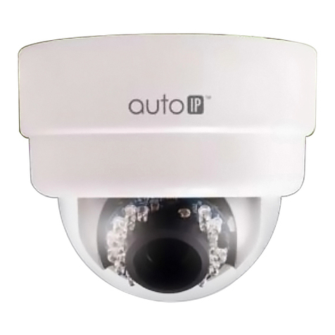
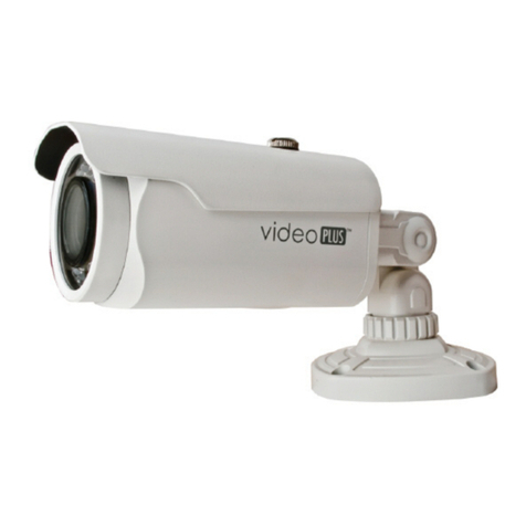
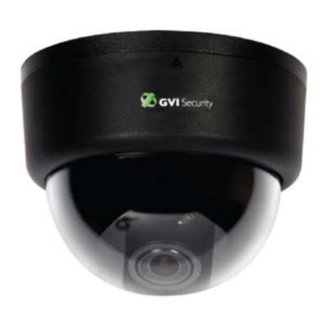
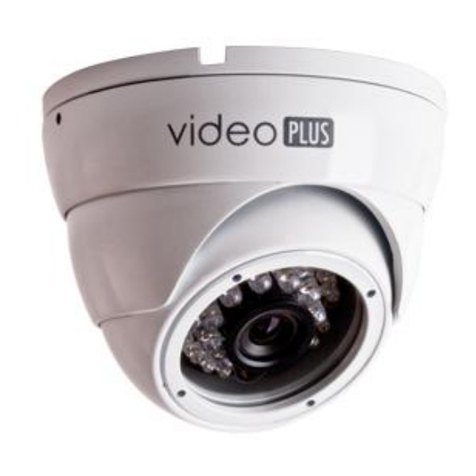
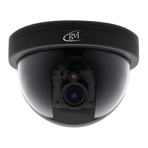
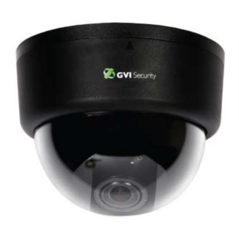
• Vandal Resistant, IR dome camera
• 1/3” Sony Su er HAD CCD
• Resolution 550TV-Lines (Color), 580TV-Lines (B/W)
• Minimum Scene Illumination
0 Lux LED On
0.5 Lux LED off
• Color & B/W Auto switchable by Photocell and Sensitivity
• Vari-Focal As herical DC Auto Iris 3.8~9.5mm F1.2 Lens Built-in
• DIP Switch control of Color & B/W changing time
• AGC, Flicker, BLC and White Balance Control.
• CDS Photocell Auto Switching IR-LED Control 18 cs LEDs
(ON: 5Lux / Off: 3Lux)
• True 3-Axis Gimbal Bracket (2-Pan, 2-Tilt)
• Vandal Resistant & Weather Resistant Housing (IP66)
• 12VDC/24VAC
Name of Each Part
8
Installation
Notes on installation and usage
1. Do not disassemble the camera.
2. Always handle the camera with care. Please avoid mechanical shock or
vibration, and take caution to revent damages or scratches on the camera
bubble due to careless storage and/or handling.
3. Do not clean the camera body with strong abrasives or soa s. When the
camera becomes dirty, clean it with a dry cloth. Use dedicated rugs to clean
lens and bubble dome cover.
4. Please kee the camera in a cool area that is not ex osed to direct sunlight.
Failing to do so can cause undesired effects on the roduct.
Camera Installation
After choosing the di switch setu a ro riate for your s ecific a lication,
follow the next guidelines:
1. Remove the rotective sheet from the rubber bottom and attach it on the base
housing.
2. Fix the base housing on the wall or ceiling with the su lied screws.
3. Unscrew the bracket screws and adjust the camera direction by turning the
an bracket left or right, tilt bracket u or down, then tighten the screws.
4. Attach the su lied service monitor cable to the service ort on the camera
and check the dis lay screen.
* Refer to age no. 7 of Name of Each Part to see its location.
5. For a brighter screen turn the DC level volume counter-clockwise, for a darker
screen turn it clockwise with a (+) driver.
* Refer to age no. 7 of Name of Each Part to see its location.
6. For a wider angle view move the zoom lever to wide, for a narrower view
angle move it to tele.
* LED board rotates along with the lens while adjusting the focus.
7. After accurate adjustment of focal length, adjust the focus lever for the
shar est focus.
8. After ro er adjustment detach the service monitor cable.
9. Firmly fix the decoration ring into lace with the screws by using the su lied
L-wrench on the base housing
PAN TILT ADJUSTMENT
Set Screw Set Screw x 2ea Set Screw x 2ea Set Screw x 2ea
