ASA Camera System (8000 Series AS)
4
Operator's Manual
2 Installation
2.1 In-Cab Display Installation
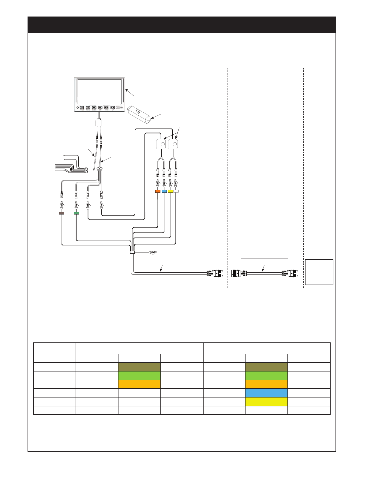
Refer to Figures 5 to 8.
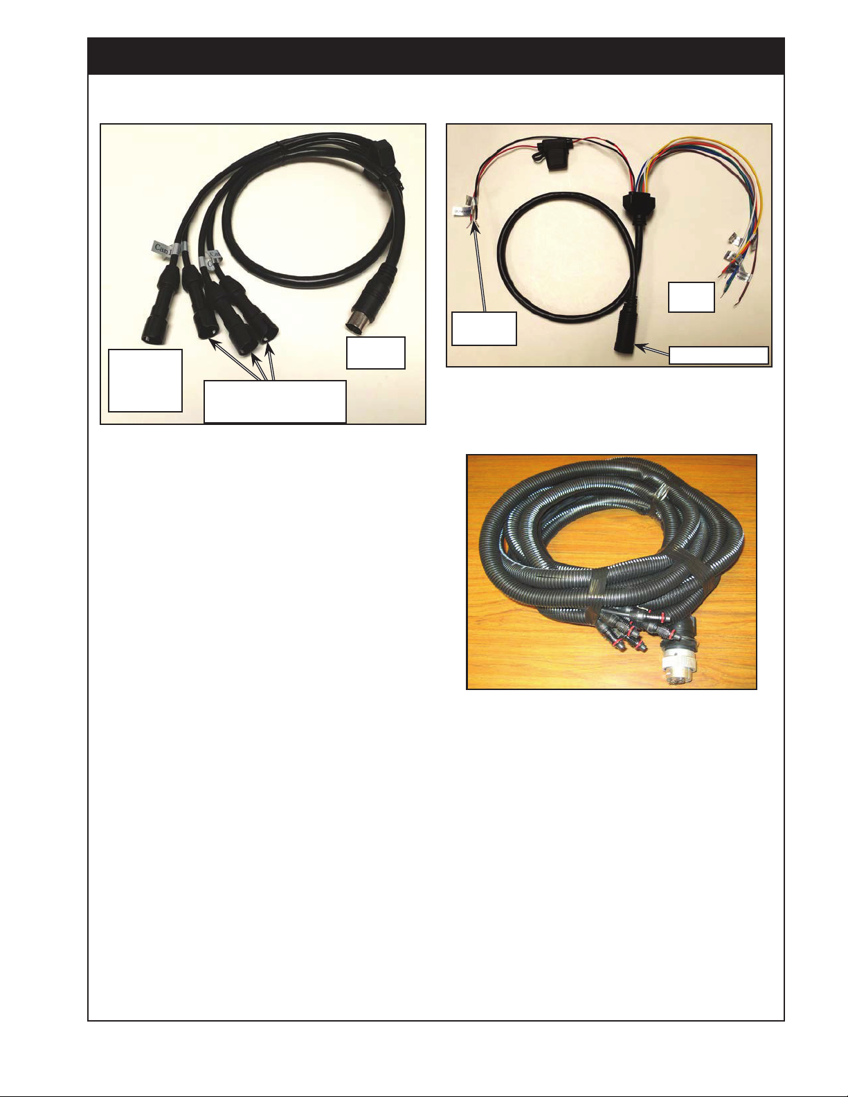
1. Connect main camera adapter harness and
power harness (multi-pin round connectors) to
the camera display.
2. Use RAM mount brackets to install the camera
display to tubular mount arms in the tractor
cab.
3. Connect power wires (red +12V, black ground)
from the power harness to switched power.
Important
Connect the power cables to switched power as
the monitor will draw some power even when off.
4. The other small colored wires on the main
harness can be looped up and disregarded.
They are used in other applications (for event
triggers) but are not required for the seeder
camera setup.
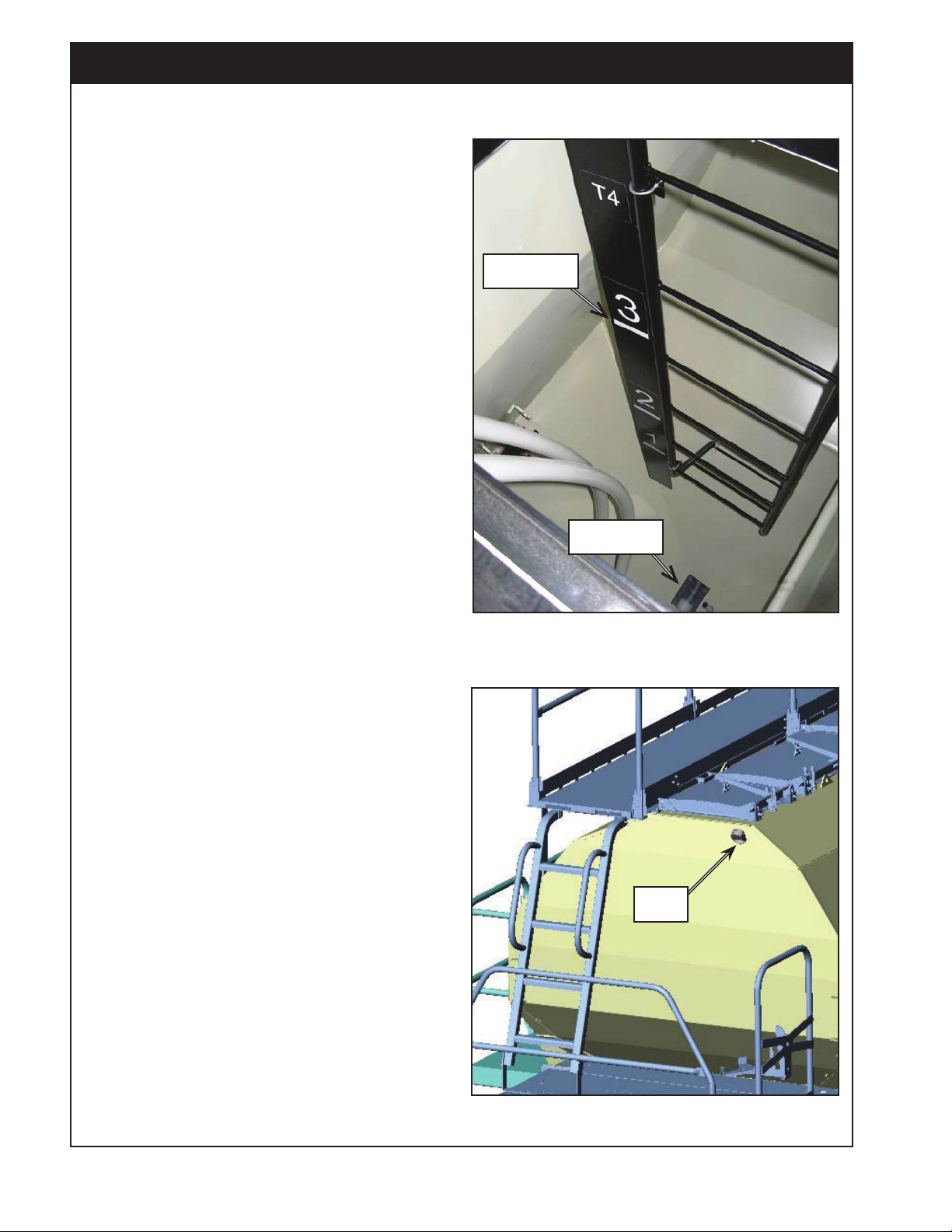
5. There are four input connectors on the main
camera adapter harness labeled CAM 1,
CAM 2, CAM 3, CAM 4.
a. Connect cable 31100014 to CAM 1 on the
main camera adapter harness.
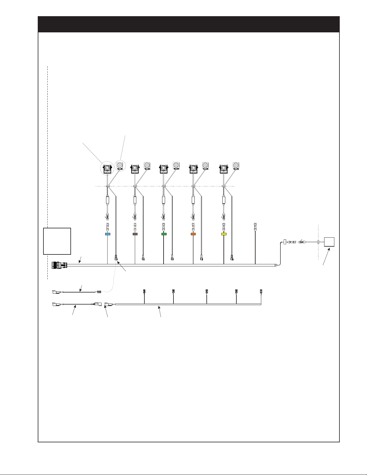
b. Then connect camera leads from tractor
harness #3122-81 (31400006) to the input
connectors on the main harness as show in
Figure 5.
c. Use the camera switches, as indicated to
run 2 cameras into one channel on the
monitor as required.
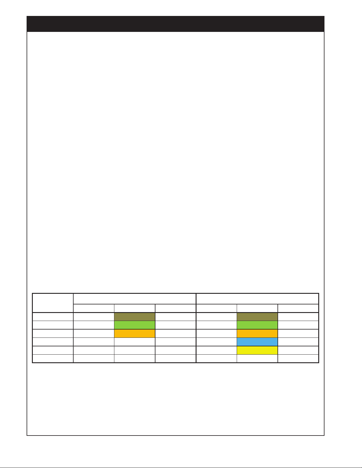
+DUQHVVOHDG &RORXU 7DQN +DUQHVVOHDG &RORXU 7DQN
Channel 1 Camera 2 Brown Tank 1 Camera 2 Brown Tank 1
Channel 2 Camera 3 Green Tank 2 Camera 3 Green Tank 2
Channel 3A Camera 4 Orange Tank 3 Camera 4 Orange Tank 3
Channel 3B ---- ---- ---- Camera 1 Blue Tank 5
Channel 4A ---- ---- ---- Camera 5 Yellow Tank 4
Channel 4B Camera 7 White Rear View Camera 7 White Rear View
,QSXW
Figure 5 - Camera Connection