SPYKER S120-4510 User manual

1009510 Rev A
Spyker Spreaders
Contact Us at 800.972.6130
This manual contains information for the safety of persons and
property. Read it carefully before assembly and operation of the
equipment!
IMPORTANT
Model S120-4510
Powered Seeder
Operator's Manual

1009510 Rev A 2
TABLE OF CONTENTS
INTRODUCTION ......................................... 2
SAFETY PRECAUTIONS ............................ 2-3
SPECIFICATIONS ........................................ 3
SAFETY DECALS AND LABELS.................. 3-4
CONTROLS ............................................ 4-5
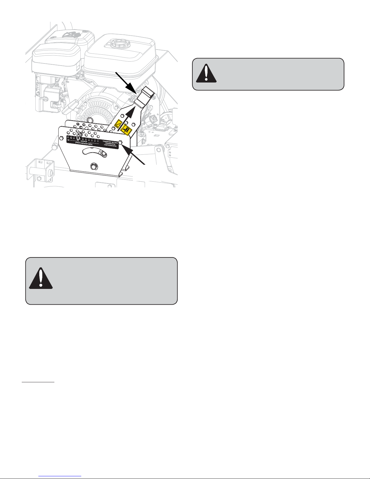
ASSEMBLY AND SET-UP .......................... 6-7
OPERATING INSTRUCTIONS.................... 7-10
MAINTENANCE AND STORAGE ............. 10-11
SERVICE AND ADJUSTMENTS .............. 11-20
WARRANTY....................................... 21-24
INTRODUCTION
UNDERSTANDING THE MACHINE SAFETY LABELS:
The machine safety labels shown in this section are placed in
important areas on your machine to draw attention to potential
safety hazards.
On your machine safety labels, the words DANGER, WARNING,
and CAUTION are used with this safety-alert symbol. DANGER
identifies the most serious hazards.
The operator's manual also explains any potential safety hazards
whenever necessary in special safety messages that are
identified with the word CAUTION and the safety-alert symbol.
Safety Alert Symbol
CAUTION: THE Spyker S120-4510
Power Seeder should only be operated
and maintained by thoroughly trained
individuals. The machines could cause
serious injury to anyone who misuses them
or does not understand their operation. All
operators and maintenance personnel are
urged to read this entire manual for their
personal safety.
NOTE: The engine manufacturer is responsible for all engine-
related issues with regards to performance, power-rating,
specifications, warranty and service. Please refer to the engine
manufacturer's owners/operator's manual, packed separately
with your unit, for more information.
SAFETY PRECAUTIONS
1.0 Training
1. Read the Operator’s Manual and other training
material. If the operator(s) or mechanic(s) cannot read
English, it is the owner’s responsibility to explain this
material to them.
2. Become familiar with the safe operation of the
equipment, operator controls, and safety signs.
3. All operators and mechanics should be trained. The
owner is responsible for training the users.
4. Never let children or untrained people operate or
service the equipment. Local regulations may restrict
the age of the operator.
5. The owner/user can prevent and is responsible for
accidents or injuries occurring to themselves, other
people or property.
2.0 Preparation
1. Evaluate the terrain to determine what accessories
and attachments are needed to properly and
safely perform the job. Only use accessories and
attachments approved by the manufacturer.
2. Wear appropriate clothing including safety glasses,
hearing protection, long pants, and safety shoes.
Long hair, loose clothing or jewelry may get tangled in
moving parts.
3. Inspect the area where the equipment is to be used
and remove all objects such as rocks, toys and wire
which can be thrown by the machine.
4. Use extra care when handling gasoline and other fuels.
They are flammable and vapors are explosive.
• Use only an approved container
• Never remove gas cap or add fuel when engine is
running. Do not smoke.
• Never refuel or drain the machine indoors.
• Always shut off the engine and permit it to cool
before removing the cap of the fuel tank.
• If the fuel container spout will not fit inside the fuel
tank opening, use a funnel.
• When filling the fuel tank, stop when the gasoline
reaches one inch from the top. This space must
be left for expansion. Do not overfill.
• Clean up oil or fuel spillage.
5. Check that safety switches and shields are attached
and functioning properly. Do not operate unless they
are functioning properly.
6. Do not remove any shield, guards, decals or safety
devices. If a shield, guard, decal or safety device is
damaged or does not function, repair or replace it
before operating the unit.
3.0 Operation
1. Never run an engine in an enclosed area.
2. Only operate in good light, keeping away from holes
and hidden hazards.
3. Be sure free wheel lever is in neutral, machine on level
surface, and parking brake is engaged before starting
engine. Always keep feet and hands clear of the engine
frame and slicer blades when starting engine.
4. Be sure of your footing while using pedestrian
controlled equipment, especially when backing up.
Walk, don’t run. Never operate on wet grass. Reduced
footing could cause slipping.
5. Slow down and use extra care on hillsides. Be sure
to travel in the recommended direction on hillsides.
Turf conditions can affect the machine’s stability. Use
caution while operating near drop-offs.
6. Slow down and use caution when making turns and
when changing directions on slopes.
7. Never raise or lower the slicer blade depth adjustment
with the slicer blades running.
8. Never operate with guards not securely in place. Be
sure all guards are attached, adjusted properly, and
functioning property.
9. Do not change the engine governor setting or over-
speed the engine.
10. Stop on level ground, disengage drive, shift free wheel
control to neutral, engage parking brake, shut off

1009510 Rev A3
engine, shut the fuel shutoff valve, and disconnect the
spark plug before leaving the machine unattended for
any reason.
11. After striking objects or if an abnormal vibration
occurs:
A. Stop slicer blades
B. Stop on level ground
C. Disengage drive
D. Shift free wheel to neutral
E. Engage parking brake
F. Shut off engine
G. Shut off fuel shutoff valve
H. Disconnect spark plug wire
I. Inspect slicer blades
Make necessary repairs before resuming operations.
12. Keep hands and feet away from the slicer blades.
13. Look behind and down before backing up to be sure of
a clear path.
14. Never carry passengers.
15. Keep pets and bystanders away.
16. Slow down and use caution when making turns and
crossing roads and sidewalks. Stop slicer blades and
place machine in transport position.
17. Do not operate the machine under the influence of
alcohol or drugs.
18. Use care when loading or unloading the machine into
a trailer or truck.
19. Use care when approaching blind corners, shrubs,
trees, or other objects that may obscure vision.
20. Watch out for rocks, small tree stumps, sprinkler
heads, water shutoff plates, etc.
21. Operate the machine in a straight line to avoid damage
to the slicer blades.
22. To avoid serious burns, do not touch the engine or
muffler while the engine is running or until everything
has cooled after the engine has been shut off.
23. Always keep both hands on the handle.
4.0 Maintenance and Storage
1. Before adjusting, cleaning, or repairing:
A. Stop slicer blades
B. Stop on level ground
C. Disengage drive
D. Shift free wheel to neutral
E. Engage parking brake
F. Shut off engine
G. Shut off fuel shutoff valve
H. Disconnect spark plug wire
2. Clean grass and debris from slicer blades, drives,
mufflers, and engine to help prevent fires. Clean up oil
or fuel spills.
3. Let engine cool before storing and do not store near
flame.
4. Shut off fuel while storing or transporting. Do not
store fuel near flames or drain indoors.
5. Park machine on level ground. Never allow untrained
personnel to service machine.
6. Use jack stands to support components when
required.
7. Carefully release pressure from components with
stored energy.
8. Disconnect battery or remove spark plug wire before
making any repairs. Disconnect the negative terminal
first and the positive last. Reconnect positive first and
negative last.
9. Use care when checking slicer blades. Wrap the
slicer blade(s) or wear gloves, and use caution when
servicing them.
10. Only replace slicer blades. Never straighten or weld
them.
11. Keep hands and feet away from moving parts. If
possible, do not make adjustments with the engine
running.
12. Keep all parts in good working condition and all
hardware tightened. Replace all worn or damaged
decals.
SPECIFICATIONS
Engine Honda GX270, recoil start.
Traction Drive Hydro-Gear transaxle
Maximum Forward Speed 0 - 2 mph, variable.
Slicer Reel Drive Clutch Brake driven with
V-belt.
Slicer Blades 10 hardened, high-carbon
steel, easily replaceable.
Seed Metering System Heavy duty cable activated
overlapping, diamond and
round-shaped holes.
Seed Agitator Ground-driven, rotor bar.
Seed Hopper 1-1/2 cubic feet,
approximately 45-lb. capacity.
Seed Types Ryegrass, Bluegrass,
Bermuda grass, fescue and
Bentgrass.
Wheels and Tires Steel wheels with 13-5 x 6
pneumatic tires.
Seeding/Dethatching Width 20 in.
Overall Width 33 in.
Weight 340 lbs.
SAFETY DECALS AND
LABELS
ATTENTION
To avoid premature
component failure,
raise front wheels
before engaging
blades.
ATENCIÓN
Para evitar la falla
prematura de los
componentes,
levante las ruedas
delanteras antes de
embragar las
cuchillas.
Se pueden producir lesiones
corporales graves si no se
sigue el procedimiento seguro
del operador.
Para evitar las lesiones:
A. Lea el manual del operador.
B. No opere la máquina sin
protecciones, cubiertas y
dispositivos de seguridad
colocados y en funcionamiento.
C. No opere la máquina cerca de
niños ni otras personas.
D. No opere esta máquina a menos
que esté capacitado.
E. Siga el procedimiento de
arranque:
i. Embrague el freno de
estacionamiento.
ii. Mueva la palanca de rueda libre
para hacer desvíos.
iii. Asegúrese de que las palancas
de control de velocidad en
tierra estén en punto muerto.
iv. Coloque el interruptor del
motor en la posición ON
(Encendido).
v. Asegúrese de que el control de
cuchillas esté desembragado.
vi. Arranque el motor.
ATENCIÓN
Serious bodily injury may
result from failure to follow
safe operator procedure.
To avoid injury,
A. Read the operator’s manual.
B. Do not operate the machine
without guards, shields, and
safety devices in place and
working.
C. Do not operate the machine
when children and/or others
are around.
D. Do not operate this machine
unless you are trained.
E. Follow start procedure:
i. Engage parking brake.
ii. Move free wheel lever to
bypass
iii. Ensure ground speed
control levers are in
neutral.
iv. Turn ON engine switch.
v. Ensure blade control is
disengaged.
vi. Start engine.
CAUTION Slicer Blade
Disengaged
Cuchilla Rebanadora
Desembragada
Slicer Blade
Engaged
Cuchilla Rebanadora
Ocupada
1009408
Serious bodily injury may result from failure to follow safe
operator procedure.

1009510 Rev A 4
To avoid injury,
A. Read the operator’s manual.
B. Do not operate the machine without guards, shields,
and safety devices in place and working.
C. Do not operate the machine when children and/or
others are around.
D. Do not operate this machine unless you are trained.
E. Follow start procedure:
1. Engage parking brake.
2. Move free wheel lever to bypass
3. Ensure ground speed control levers are in neutral.
4. Turn ON engine switch.
5. Ensure blade control is disengaged.
6. Start engine.
ATTENTION:
To avoid premature component failure, raise front wheels
before engaging blades.
To avoid injury,
keep hands and
feet away from
rotating blades.
DANGER PELIGRO
Para evitar
lesiones, mantenga
las manos y los
pies alejados de
las cuchillas de
rotación.
1009409
DANGER:
To avoid injury, keep hands and feet away from rotating
blades.
To avoid injury,
do not operate
machine without
safety shields in
place.
WARNING ADVERTENCIA
Para evitar las
lesiones, no opere la
máquina sin las
cubiertas de
seguridad colocadas.
1009412
WARNING:
To avoid injury, do not operate machine without safety shields
in place.
CAUTION:
To avoid injury, keep fingers away from the clevis pin on the
slicer blade depth adjustment handle.
CONTROLS
Note: Please familiarize yourself with the names and
functions of the controls specified in this section as their
descriptions are used throughout this manual.
Fuel
Shutoff
Valve
Engine
Choke
Control
Lever Recoil
Starter
Engine
Switch
Spark
Plug
Handle Removed
For Clarity
1. Engine Switch:
Move to the ON position to start and run the engine. Move to
the OFF position to stop the engine.
2. Fuel Shutoff Valve:
Move to the ON position to allow fuel to flow from the fuel tank
to the engine. Move to the OFF position to stop fuel flow to the
engine.

1009510 Rev A5
3. Engine Choke Control Lever:
Place in the closed position when starting a cold engine.
Position the lever halfway between open and closed when the
engine starts and to the full-open position once the engine has
warmed up.
4. Recoil Starter:
To start the engine, set the choke and the throttle and grasp
the starter grip and pull slowly until the starter engages. Then
pull the cord sharply to start the engine. Repeat if necessary
with the choke opened slightly.
Parking
Brake
Lever
Free Wheel
Lever
Slicer Depth
Lever
5. Slicer Depth Lever:
Adjust the slicer blades from transport to dethatching or
slicing. To adjust the slicer depth:
1. Press down on the operating handle to remove weight
from front wheels.
2. Squeeze the lock handle and move slicer lever to
achieve desired depth of cut between 1/4 in. above
ground to 1 in. into ground.
6. Free Wheel Lever:
BYPASS
(FREE WHEEL)
DESVÍO
(RUEDA LIBRE)
OPERATION
(DRIVE)
OPERACIÓN
(ACCIONAMIENTO)
Controls Bypass (free wheel) and Operation (drive) functions
of the trans-axle. Push in and down for Bypass. Pull out and
down for Operation.
7. Parking Brake Lever:
Pull up to release parking brake. Pull out and down to engage
parking brake.
Forward
Ground Speed
Control Lever
Reverse
Ground Speed
Control Lever
Seed Flow
Metering
Gauge
Engine
Throttle
Lever
Seed Flow
Lever
Slicer Blade
Control
Lever
8. Engine Throttle Lever:
Moving the throttle lever from the front to the rear decreases
the engine speed. To start the engine, position the throttle
halfway between slow and fast
9. Forward / Reverse Ground Speed Control
Levers:
Located on the right side of the control handle is the forward
ground speed control lever. The left lever is for reverse. These
two levers control the maximum output of the hydrostatic
trans-axle and thus the ground speed of the spreader

1009510 Rev A 6
ASSEMBLY AND SET-UP
A. Assembly
1. Remove top and sides of shipping container.
2. Locate and remove literature pack from seed hopper.
3. Cut all nylon straps retaining machine to shipping
container.
4. Cut nylon strap holding blade engagement handle to
handlebar.
5. DO NOT CUT the nylon straps that hold the control
cables to the handlebar.
Remove Pin
From Both
Sides
6. Remove hairpin and clevis pin (both sides) from handle
bar pivot and rotate handlebar into working position.
Re-Install The
Pin On Both
Sides
Pivot
7. Pivot control handle into position and re-install clevis
pin and hair pin both sides.
independent of the engine speed. Pulling the right lever
rearward increases the forward speed and pulling the left lever
rearward increases the reverse speed. Do not move both
levers in unison, only pull one at a time. To start the engine,
ensure both levers are in their neutral position. Forward
motion is variable based on where the lever is positioned in the
forward mode. To operate the unit in reverse, the reverse lever
must be held.
10. Seed Flow Lever:
Move the lever forward to open the seed plate allowing seeds
to flow through the openings. Move the lever to the rear to
stop seed flow. To close the hopper gate, place the handle in
locked position.
11. Seed Flow Metering Gauge:
Adjust seed flow by loosening the knob, rotating the dial stop to
the desired setting and then tightening the knob to lock. When
ready to drop seed, release handle from locked position and
push forward. See the seeding table underneath the lid of the
hopper for seeding rates.
12.Slicer Blade Control Lever:
When the lever is pulled back, the slicer blades rotate. To
disengage the slicer, release the lever. The lever must be
disengaged to start the engine. To prevent damage to the unit,
always lift the front wheels off the surface before engaging the
slicer control lever.

1009510 Rev A7
NOTE: If the engine did not start during the Free Wheel
and the Slicer Blade Control safety switch test then the
unit is functioning properly.
OPERATING INSTRUCTIONS
CAUTION: AVOID INJURY. Read
and understand the entire Safety
Precaution section before proceeding.
Fuel
Cap Oil Service
Port
A. Checking the Engine Oil
To check the engine oil, locate the oil service port as
shown in the diagram above.
Refer to the engine manual for proper operation level.
Fill to the proper level with 10W-30 engine oil rated for
service SE or SF.
B. Filling With Fuel
1. Place unit in an open or well-ventilated area.
2. Stop the engine and allow it to cool.
3. Clean the fuel cap and the area around the fuel cap to
prevent dirt from entering the fuel tank. Remove the
cap.
4. Fill the fuel tank to within 1 in. of bottom of filler neck.
5. Replace fuel cap and tighten.
6. Clean up any spilled fuel.
B. Set-Up
1. Check tire pressure. Proper operating pressure is 20
psi.
NOTE: Tires may be overinflated to properly seat the
bead to the rim. Reduce pressure if necessary.
2. Check the engine oil level. See “Checking the Engine
Oil” on page 7.
3. Move the unit outdoors and check and add fuel. See
“filling with Fuel” on page 7.
4. Ensure the unit is in transport position. See
“Transport Position” on page 8.
5. Push the unit to a test area where the operator can
run the unit and become familiar with its controls
before it is placed into service.
CAUTION: AVOID INJURY. Read
and understand the entire Safety
Precautions and Operating sections
before operating the unit.
6. Operate all controls until operator is familiar with every
control and motion of the unit.
C. Safety Systems Test
The safety systems installed on your unit should be checked
before each use. Read the operator manual and be completely
familiar with the operation of the unit before performing
these checks. Use the following procedures to check for
normal operation. If there is a malfunction during one of these
procedures, do not operate unit. See dealer for service. Before
performing the safety systems test, the engine must be set
up as noted in section B of assembly and set up. Perform all
tests in a clear open area with no bystanders.
D. Engine starting test
1. Ensure that the Slicer Blade Control lever is up
(disengaged).
2. Ensure the Free Wheel lever is in by-pass (neutral).
3. Ensure the Slicer Blade height adjustment is in
transport position.
4. Reconnect spark plug wire.
5. Move engine switch to the ON position.
6. Open the fuel shut-off valve.
7. Set the choke to the closed position (if cold)
8. Set the throttle half way between slow and fast
9. Pull recoil string sharply to start engine. RESULT:
The engine should start.
10. Turn off the engine at the off engine switch.
E. Free Wheel Safety Switch Test
1. Chock wheels to keep unit from moving.
2. Ensure that slicer control lever is disengaged.
3. Place the Free Wheel lever in Operation position.
4. Turn ON engine switch, and attempt to start the
engine, using choke if necessary. RESULT: The
engine should not start.
F. Slicer Blade Control Lever Safety
Switch Test
1. Place the Free Wheel Lever in Bypass position.
2. Place the slicer blade control lever in the down
(engaged) position.
3. Turn ON engine switch, and attempt to start the
engine, using choke if necessary. RESULT: The
engine should not start.

1009510 Rev A 8
A
Transport
Position
C. Transport Position
1. To move the unit to and from the work area without
damaging components or turf, always place the slicer
blades in its highest position. Squeeze the lock handle
and move slicer depth lever (A) fully forward to raise
the slicer blades. Release the lock handle and ensure
that depth handle is locked in position.
Danger: Do not transport the unit with
the slicer blades engaged. Release the
slicer control lever and allow the slicer
blades to fully stop before attempting to
raise unit height.
D. Moving the Unit With the Engine Stopped
1. Ensure the Parking Brake is disengaged.
2. Place the Free Wheel Lever in the Bypass position and
push/pull the unit by the handlebars. Do not tow.
E. Starting and Shut-Off NOTE:
Slicer Blade lever must be disengaged and traction control
lever in the bypass position for engine to start.
A. STARTING
1. If disconnected, connect spark plug wire.
2. Move Free Wheel Lever to neutral position.
3. Open the fuel shutoff valve.
4. Move the engine switch to the ON position.
5. Move the choke lever to the closed position (cold
engine) or half-open position (warm engine).
6. Move the throttle lever half way between slow and
fast.
7. Grasp the recoil starter grip and pull slowly until the
starter engages and then pull the cord with a rapid
full motion. Allow the cord to recoil slowly. Repeat if
necessary with the choke opened slightly.
8. Move the choke lever to the half-open position and
allow the engine to warm up. Then, open the choke all
the way and move the throttle lever to fast.
Danger: Avoid Injury! Always ensure that
slicer blades have come to a complete
stop before leaving operator’s position
B. SHUT-OFF
1. Release slicer blade control lever and wait for slicer
blades to stop rotation.
2. Move throttle lever to slow setting and allow engine to
return to idle.
3. Move engine switch to OFF position.
4. Move the fuel shutoff valve to the OFF position.
F. Moving Forward and Backward
A. TO MOVE UNIT FORWARD
1. Ensure the parking brake is off.
2. Move the throttle to full open position.
3. Pull the Forward Ground Speed Lever to move
machine forward. The further the handle is pulled, the
faster the machine travels.
B. TO MOVE UNIT BACKWARD
1. Ensure the parking brake is off.
2. Release slicer blade control lever and wait for slicer
blades to stop rotating.
3. Pull the Rearward Ground Speed Lever to move
machine rearward.
IMPORTANT: Avoid damage. Do not operate in
reverse with slicer engaged.
C. TURNING UNIT
IMPORTANT: Avoid damage. Do not turn unit with
blades engaged in ground.
1. When ready to turn, decrease speed.
2. Press down on handle bars to raise seeder front end
off ground.
3. Turn unit.
4. Slowly lower unit back to ground.
5. Increase to desired speed.
G. Filling Seed Hopper
1. Move the Seed Flow Lever to the OFF position.
2. Open hopper cover lid.
3. Fill hopper. Hopper capacity is 1.5 cubic feet
(approximately 45 lbs.).
During operation, the seed level can be monitored at the
seed level indicator window on the rear of the hopper.
Refill the hopper when seed is no longer visible in the
indicator window.
H. Setting Seed Flow Rate
1. Seed flow rate is set by adjusting the seed flow
metering dial located on the control panel. The table
below provides the settings for approximate seeding
rates. A copy of this table can be found under the lid
of the seed hopper on the unit.

1009510 Rev A9
I. To Adjust Seed Flow Rate:
D
B
A
C
1. Move seed flow control lever (D) to the OFF position.
2. Loosen the threaded knob (A).
3. Rotate the adjustment stop (B) to the desired setting
on the label gauge (C).
4. Tighten knob (A) to lock setting.
J. Starting and Stopping Seed Flow
1. Move the flow control lever (D) forward to open the
seed flow plate.
2. Move the control lever backward to close the seed
flow plate.
K. Setting Slicer Depth
Slicer blades can be set to a maximum slicing depth of 1.0
in. (The slicing blades have a 1 in range of movement to
account for blade wear.)
• For dethatching, the blades should just graze the
ground.
• For seeding, the blades should be set to achieve the
desired depth for the seed being planted.
• Keep feet from under machine when adjusting slicer
depth.
• Avoid pinch point at slicer depth adjustment handle.
Danger: Avoid Injury! Always ensure that
slicer blades have come to a complete
stop before leaving operator’s position
A. TO ADJUST THE SLICER DEPTH
1. Move seed flow control lever to OFF position.
2. Disengage slicer control lever and wait for slicer
blades to stop rotating.
3. Place Ground Speed Lever in neutral.
A
B
C
4. Move the slicer depth locator pin (A) to the desired
location.
5. Squeeze the lock handle (B) and move slicer lever to
the depth locator pin to achieve desired depth of cut.
6. Release the lock handle (B).
7. To avoid pinch point keep fingers away from bottom of
latch plate (C).
Danger: Avoid Injury! Ensure feet are
clear of machine when lowering.
NOTE:
• For 1/4” penetration set the slicer depth locating pin at
position # 4.
• In full-rearward position the slicer blades are at
maximum slicing depth.
• In full-forward position (transport; as shown) the slicer
blades are fully off the surface.
L. Slicing and Seeding
IMPORTANT: Before engaging slicer, raise front wheels off the
Ground by pressing down on the handlebar. Failure to do this

1009510 Rev A 10
when starting the slicer stresses components and may result
in premature parts failure.
1. Select the desired slicing depth and seed flow rate.
2. Push down on the center of the handle to lift the front
wheels off the ground.
3. Pull the slicer control lever back to the handlebar and
hold to start the slicer reel.
4. Release the pressure on the handlebar and slowly
lower the front of the unit to the ground.
5. Move the seed control lever to the open position.
6. Select the desired forward speed with the forward
ground speed control lever.
M. Guidelines for the Application of Seed
1. Operate the unit in a straight line.
2. Before reaching the end of the first pass, use the
forward ground speed control lever to slow the unit,
close the seed flow lever and press down on the
handlebar to lift the rotating slicer reel out of the
ground.
NOTE: The slicer reel will not stop rotating unless the
slicer control lever is released.
3. Turn the unit around 180 degrees and align it for a
proper overlap.
4. Release pressure on the handlebar and slowly lower
the front of the unit.
5. Move the seed flow lever to the open position and
start the second pass, resuming normal operating
speed.
NOTE: For best results, renovate each area in two
directions, 90 degrees apart (See illustration above),
at 1/2 the total seeding rate.
6. When renovating an area surrounded by walkways or
driveways, make at least two complete passes around
the perimeter. This will provide enough room to make
turns at the end of each pass without the slicer blades
contacting concrete or asphalt.
MAINTENANCE AND
STORAGE
Warning: Avoid Injury! Disconnect
the spark plug before performing any
maintenance.
A. General Maintenance
1. Refer to the engine owner’s manual furnished with the
unit for complete maintenance instructions for the
engine.
2. Do not tamper with the engine’s governor settings.
They are factory set to provide the proper maximum
engine speed.
3. If the unit must be tipped up on its side for
maintenance, first drain the fuel from the fuel tank and
the oil from the engine’s crankcase.
4. Be careful not to spill oil on the drive belts.
B. Daily Maintenance After Spreading
1. Park the unit outside the storage facility with the
engine shut off.
2. Disconnect the spark plug wire and close the fuel
shutoff valve.
3. Permit the machine to cool.
4. Clean the machine, under the frame, and around
slicer blades.
5. Check all of the slicer blades. Check that the blade
axle bearing bolts are tight. See “Replacing Slicer
Blades” on page 14.
6. Check the engine oil level, fuel level, and air cleaner
(See engine manual for instructions)
7. Place the unit in locked storage to avoid tampering or
use by an untrained operator.
8. Check that all fasteners are tight.
C. Maintenance Every 100 Hours
NOTE: Service more frequently under severe operating
conditions.
1. Check the condition and tension on all belts.

1009510 Rev A11
Oil (both
sides where
applicable)
2. Lightly oil the following:
• The slicer depth adjusting lever pivot
• The depth control rod and linkage pivots
• The slides that connect the seed hopper to the
power deck.
3. Grease the axle bearings at the zerk.
4. Inspect all parts for rust. Replace if necessary.
D. Maintenance Every 200 Hours
NOTE: Service more frequently under severe operating
conditions.
Oil Seed
Flow
Metering
Plate
• The seed flow metering plate where it slides
against the bottom of the seed hopper.
Oil Hinge
1. Lightly oil the following:
• The hinge on the lid of the seed hopper
E. Storage
1. SHORT TERM
• NEVER spray unit with high-pressure water or store
unit outdoors.
• Inspect unit for visible signs of wear, breakage or
damage.
• Keep all nuts, bolts and screws properly tightened
and know that the unit is in safe working condition.
• Store unit in a cool, dry protected area.
2. LONG TERM
• Clean unit thoroughly with mild soap and low-
pressure water and lubricate. Touch up all
scratched painted surfaces.
• Remove weight from wheels by putting blocks under
frame or axle.
• Inspect all parts for rust and replace if necessary.
3. FUEL SYSTEM
NOTE: Gasoline left in the fuel system for extended
periods without a stabilizer will deteriorate, resulting
in gum deposits in the system. These deposits can
damage the carburetor and the fuel hoses, filter
and tank. To prevent deposits from forming in the
fuel system during storage by adding a quality fuel
stabilizer to the fuel. Follow the recommended mix
ratio found on the fuel stabilizer container. To treat
the fuel system for storage:
• Add fuel stabilizer according to manufacturer’s
instructions.
• Run engine for at least 10 minutes after adding
stabilizer to allow it to reach the carburetor.
• IMPORTANT: NEVER store the engine with fuel in the
fuel tank inside of a building with potential sources of
ignition.
4. TO TAKE THE UNIT OUT OF STORAGE:
• Refer to the engine service manual to prepare the
engine for service.

1009510 Rev A 12
SERVICE AND
ADJUSTMENTS
Warning: Avoid Injury! Disconnect the
spark plug wire to prevent the engine
from accidentally starting before
performing any adjustments.
A. Tightening the Transmission Belt (After
8 Hr)
A
1. Turn off engine and ensure that the spark plug (A) is
disconnected.
2. Chock rear wheels.
A
AB
A
3. Remove six hex bolts (A) retaining left side belt cover
(B) and remove cover (B).
AB
4. Remove the four hex bolts (A) that retain the rear
maintenance cover (B).
A
5. Loosen the 5/16 in hex nuts (A) holding the bracket
pulley to remove belt tension.

1009510 Rev A13
D
C
A
B E
Level
6. Push the LH side (A) of the bracket pulley down and
tighten the LH nut (B) slightly to hold the bracket at an
angle.
7. Using a small crow bar reach in from the rear and
pull up on the crow bar to push down on the bracket
pulley until the transmission drive belt (C) is level with
the transmission sheave (D), tighten up the RH nut (E)
completely.
8. Tighten the 5/16 hex nuts (B,E).
9. Check Transmission belt (C) for tension. There should
be 3/16 in. deflection when belt is pushed by hand.
10. Replace both safety covers.
B. Replacing Slicer Drive Belt
1. Ensure that the engine is off.
2. Disconnect the spark plug.
3. Ensure that the rear wheels are chocked.
4. Ensure that the slicer control lever is not engaged.
A
AB
A
5. Remove hex bolts (A) retaining left side belt cover (B)
and remove cover (B).
A
B
Hex bolt on other
side of Tensioner.
6. Loosen hex bolt retaining tensioner (B) to remove belt
tension.
7. Remove slicer drive belt (A) from pulley and engine
sheave.
8. Install replacement belt (A) on pulley and engine
sheave. NOTE: Install idler pulley on inside of belt, as
shown.
9. Turn bolt on tensioner until tensioner (B) is set at the
4th tick mark, and re tighten the hex bolt.
10. Re-install the belt cover.

1009510 Rev A 14
C. Adjusting Slicer Drive Control Cable
The slicer drive control cable should be adjusted so that there
is no slack in the cable when the control lever is disengaged.
Do not over-tighten.
B
A
Slide to
adjust slack
1. Remove the pulley guard.
2. Loosen nuts (B) that attach cable bracket (A) to handle
weldment.
3. Slide cable bracket (A) forward or reverse to remove
slack between cable eyelet and clutch brake. No slack
should exist. Adjust so that slack is removed from the
cable without beginning to move the clutch brake arm.
4. Tighten cable bracket nuts (B).
5. Re-install pulley guard.
D. Replacing Slicer Blades (Every 2 yr)
1. Ensure that the engine is off.
2. Disconnect spark plug
3. Ensure that the slicer control lever is not engaged
4. Ensure that the rear wheels are chocked.
5. Raise the front or (Hopper end) up on jack stands no
higher than 8.0”
A
AB
A
6. Remove hex bolts (A) retaining left side belt cover (B)
and remove cover (B).
A
B
Hex bolt on other
side of Tensioner.
7. Loosen hex bolt retaining tensioner (B) to remove belt
tension.
8. Remove slicer drive belt (A) from pulley and engine
sheave.

1009510 Rev A15
III
III
9. Remove pulley at slicer by:
I. Unscrew key set screw. Using a 7/16 in. wrench,
unscrew each of the 1/4” bolts from the bushing.
II. After removing the bolts, re-install one into each of
the three threaded holes on the bushing.
As you tighten the bolts, the bushing should
separate from the pulley.
III. Remove the bushing and pulley from the shaft.
NOTE: The shaft has a key at the end where the
pulley is assembled which may come out when you
remove the pulley. In the event that this happens,
please take care not to lose the key. The slicer
blades will not turn without the key.
Loosen and remove
bolts on both sides
10. Remove the 1/2” hex bolts and 1/2” hex nuts that
attach bearings to engine frame (note (2) bolts on
each side of frame).
Remove
11. Remove the complete blade assembly with bearings.

1009510 Rev A 16
H
IJ
K
A
L
ABCDF
E
NOTE:
Blade Orientation
NOTE:
Blade
Orientation
12. Loosen the set screws and slide the bearings (A) off of
each end.
13. Slide off the plastic washers (B) off one end and
washers (L) and axle retainers (K) off opposite end.
14. Set the blade assembly on a work bench or other
sturdy work surface and use 2 blocks of wood on
each side wedged at blade notch to keep the blade
assembly from rolling off the bench.
15. Clamp the complete assembly down to the work bench
or table using nylon straps. NOTE: The nylon straps
should be placed on the parts of the axle that are over
the blocks of wood to prevent axle from bending.
16. Remove the 1-1/8” hex nut (C), lock washer (D),
washers (E), small spacer (F), and large washer (G).
17. Remove each blade(I) and spacer (J) taking note of
each blade orientation.
HIJ
NOTE: Blade
Orientation
NOTE: Every Blade is
Rotated 90 Degrees
from the Previous
One
18. Place new blade (I) with cutting edge facing forward
(as shown) on axle (H) along with the spacer.
19. Replace all the blades (I) and spacers (J) making sure
to stagger the blade orientation for every other blade.
20. At the non-threaded end of the axle (H), replace (K),
(L), and (A).
21. At the threaded end of the axle (H), replace (F), as
shown. Ensure that small spacer (F) is protruding
out from square axle. Square axle should be inside of
small spacer for proper tightening.
22. Brush the threads of axle (H) with anti-seize, and add
(2x,E), (D), and (C) to the end of the axle. Torque the
nut to 200 lb-ft.
23. On the nut side of the axle slide plastic washers (B)
and bearing (A) on to shaft. Unclamp assembly.
24. Slide the complete assembly with bearings into
position on the machine frame, install the 1/2” hex
bolts and nuts into the frame to secure the bearings
and re torque the bolts to 63 lb-ft (note 2 bolts ea
side). Ensure bearings do not clamp axle assembly
together. There should be no side load on bearings.
Remove either one (B) or (L) if required. After
tightening, ensure blades spin freely by hand.

1009510 Rev A17
III
III
B
A
25. Reinstall pulley on the end of the slicer that was
previously removed:
I. Using a 7/16 in. wrench, unscrew each of the
1/4” bolts from the bushing.
II. Assemble the bushing the the pulley using three
1/4 in. bolts as shown. Install the bolts and lock
washers through the un-threaded holes on the
bushing, and through the threaded holes on the
pulley. NOTE: It is very important to assemble
the pulley exactly as specified. Failure to do so
may result in making it difficult to disassemble the
components in the future.
III. A. Assemble the pulley to the axle as shown.
If the square key fell out of the axle during
disassembly, replace it and use it to align the
bushing’s key groove with the key on the axle.
NOTE: Align outside of pulley to outside of
clutch brake pulley with a straight-edge. Failure
to do so could cause the slicer assembly belt to
come off during use.
B. Using a 7/16 in. wrench, tighten the 1/4 in.
bolts into the bushing. Take care to ensure that
the bolts are evenly tightened. Turn one bolt a
quarter of a turn into the pulley and then move
to the next bolt and tighten the same amount.
Keep alternating between bolts when tightening
until the bushing is completely tightened to the
pulley. NOTE: As it becomes more difficult to
tighten the bolts, reduce the amount of turning
that is applied to each bolt as you alternate.
Apply thread locker (such as Loctite) to set
screw for key, and tighten set screw.
26. Install slicer blade belt on pulley and engine sheave.
NOTE: Install idler pulley on inside of belt (see steps 7
and 8).
27. Turn bolt on the tensioner until the tensioner is set at
the 4th tick mark, and re tighten hex bolt.
28. Install pulley guards.
E. Replacing the Clutch Brake and/or
Transmission Belt
To replace the transmission belt you must first
remove the clutch brake (see steps 1 to 11):
1. Disconnect spark plug.
2. Ensure that slicer control lever is not engaged.
A
AB
A
3. Remove hex bolts (A) retaining left side belt cover (B)
and remove cover (B).
A
B
Hex bolt on other
side of Tensioner.
4. Loosen hex bolt retaining tensioner (B) to remove belt
tension.
5. Remove slicer drive belt (A) from the pulley and engine
sheave.

1009510 Rev A 18
A
6. Loosen the transmission belt mule drive nuts (A).
Remove
7. Remove 1/4” carriage bolt, washer, and nut between
clutch brake lever and bracket.
D
B
C
E
F
A
G
H
I
8. Remove 5/16” nut (A) between clutch brake (B) and
clutch brake bracket (C).
9. Remove long 7/16” bolt (D), lock washer (E), and
washer (F). Do not remove spacer (I).
10. Lift up on the transmission belt (G) and remove it from
the clutch brake (B). Allow the transmission belt (G)
to fall below the engine output shaft (H).
11. Remove clutch brake (B).
AB
12. Remove 4 bolts that retain the rear maintenance
cover.
To replace the transmission belt follow steps (13 to
26). To replace the clutch brake pulley, proceed to
step 15.
Replace AB
C
D
13. Un-wrap transmission belt (B) from mule drive (C) and
transmission (B).
14. Replace new transmission belt (A) onto transmission
(B) and mule drive (C). Temporarily rest the “free end”
of the transmission belt (A) on the engine output shaft
(D) as shown above.

1009510 Rev A19
The following steps must be completed regardless of
whether you were replacing the clutch brake and/or
the transmission belt.
D
B
C
E
F
A
G
H
I
15. Ensure spacer (I) is still installed. Lift the “free end”
of the transmission belt (G) off the engine output shaft
(H) and replace clutch brake (B). Ensure that the
transmission belt (G) rests in the groove of the clutch
brake (B).
16. Reinstall the washer (F), lock washer (E), and long
7/16” bolt (D) that were removed in step 9. Tighten
bolt to 63 lb-ft.
17. Reinstall the 5/16” nut (A) that was removed
previously.
Reinstall
18. Reinstall the 1/4” carriage bolt and nut that were
removed previously between clutch brake lever and
bracket.
D
C
A
B E
Level
19. Push the LH side (A) of the bracket pulley down and
tighten the LH nut (B) slightly to hold the bracket at an
angle.
20. Using a small crow bar reach in from the rear and
pull up on the crow bar to push down on the bracket
pulley until the transmission drive belt (C) is level with
the transmission sheave (D), tighten up the RH nut (E)
completely.
21. Tighten the 5/16 hex nuts (B,E).
22. Check Transmission belt (C) for tension. There should
be 3/16 in. deflection when belt is pushed by hand.
Reinstall
23. Reinstall the four bolts that secure the rear
maintenance cover as shown.

1009510 Rev A 20
A
B
Hex bolt on other
side of Tensioner.
24. Install slicer blade belt (A) on pulley and engine sheave.
NOTE: Install idler pulley on inside of belt as shown.
25. Turn hex bolt on tensioner (B) until tensioner is set
between 4th tick mark. Tighten hex bolt.
A
AB
A
26. Reinstall cover (B) and hex bolts (A) that were
removed previously.
G. Ground Speed Adjustment
A
BB
A
1. Loosen 5/16” nuts (A).
2. Rotate threaded rods (B) to adjust ground speed.
Increasing the visible length of the threaded rods will
slow ground speed, and decreasing the visible length
of the threaded rods (B) will increase the ground
speed. The left rod adjusts reverse speed, and the
right rod adjusts the forward speed. The two rods
can be adjusted independently.
3. Re-tighten 5/16” nuts (A) when you are finished
adjusting the ground speed.
4. The material calibration chart on this machine
assumes a ground speed of 2 mph is used. If ground
speed is changed, the material flow rate needs to be
recalibrated.
TROUBLESHOOTING:
Symptom Possible Cause Solution
Unit does not have
forward power up
hills.
Transmission belt
is loose. See “Tightening
Transmission Belt”
on page 12.
Blades continue
to spin after slicer
blade control is
disengaged
Slicer blade pulley
belt is loose. Replace slicer
blade pulley belt.
See “Replacing
Slicer Drive Belt”
on page 13.
Clutch brake has
failed Replace clutch
brake. See
“Replacing the
Clutch Brake and/
or Transmission
Belt” on page 17.
Table of contents
Popular Seeder manuals by other brands

KingKutter
KingKutter Seeder none Operation and parts manual

John Shearer
John Shearer Pasture Renovation Drill Operator's manual

Land Pride
Land Pride MPS2607 Operator's manual

Precision
Precision GS2010 owner's manual

ASIA TECHNOLOGY
ASIA TECHNOLOGY ARP-8S(F) operating manual

Bourgault
Bourgault PKG I2I CMPNT NA Installation & setup