ASAIR AHS01IB User manual

Absolute Humidity Sensor
product manual
AHS01IB
For more detail please check:www.aosong.com

Features
Working power voltage:+5V
Operating temperature: -5 to +200℃
(Humidit detection part)
full calibrated
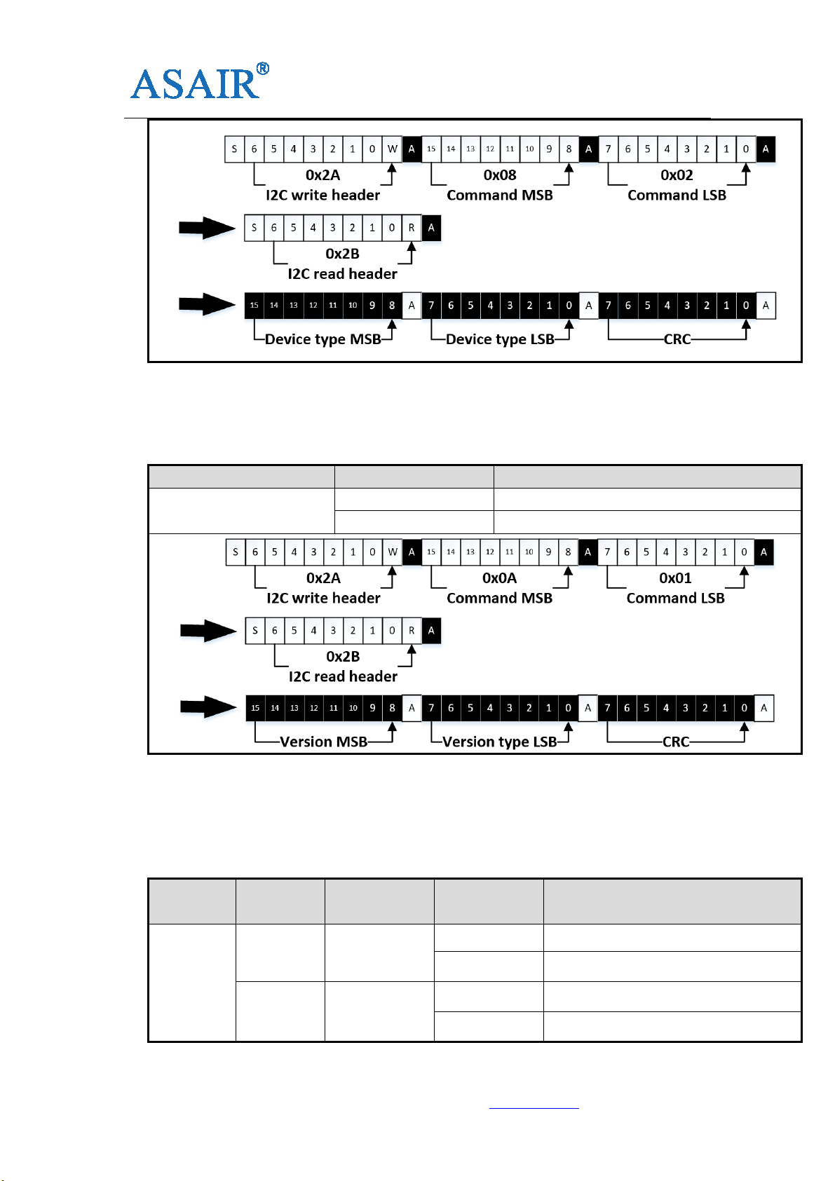
I2C digital interface communication
Power consumption:120mW(maximum)
Zero-free drift
Ver long operation life
High resistance to pollution
Low humidit lag error
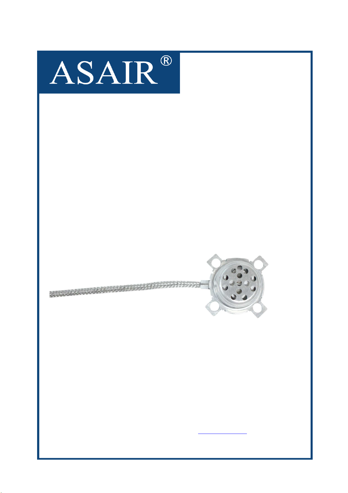
Description
AHS01IB is an absolute humidit sensor
with ultra-high response speed, high
temperature resistance, high accurac and
full calibration. Modern manufacturing
process ensures high reliabilit and
excellent long-term stabilit . The sensor
includes a humidit detection sensor
connected to a CMOS microprocessor with
a high performance integrated 24bitAD.The
product has the advantages of excellent
qualit , ultra-high response speed, strong
anti-interference abilit and ver high cost
effective. With high integration performance,
it is perfectl meet the requirements for
high-qualit mass production.
AHS01IB has I2C digital interface with ver
small size and ver low power consumption.
The working voltage for AHS01IB is 5 Volt
suppl voltage, it could be used to all kinds
of common application scenario provides
low cost and ver low power consumption
advantages. AHS01IB has been calibrated
in high accurac constant temperature and
humidit chamber from our factor , the
output is the real value of environmental
humidit , users can get the accurate
humidit value directl without an signal
processing, which help customers to save
the costs and make the further job much
easier.
Applications
Microwave Humidit Control, Dr er Humidit
Detection, Oven Smart Control, Industrial
Measurement, Air Conditioning and Moisture
Control, Ph sical and Chemical Instruments,
Steam Bath, etc.

AHS10
-1-
Guangzhou Aosong electronics co., LTD Tel:400-630-5378 www.aosong.com v1.1_20180623
1.Sensor Accuracy
1.1 Accuracy parameters
Table1: AHS01IB performance table
Parameter Condition TYP Units
Operating Range
1atm 0~∞ actual value
T pical output +60℃,30%~
+60℃,60% 900~1300 actual value
Accurac 1atm ±200 actual value
Repeatabilit 1atm ±5% actual value
Stabilization time
Power on 8±5 second
Humidit
response 90% response 12±5 second
1.3 Temperature and umidity conditions
Table3: AHS01IB Temperature and umidity conditions
Parameter Condition TYP Units
Operating
Temperature Range
Tsensor -5~+200 ℃
CPU Temperature
Range Twork -20~+85 ℃
Storage Temperature
Tstor -20~+85 ℃
Storage humidit Hstor 20%~60% RH
1.2 Sensor material c aracteristics
Table2: Sensibility and materials
Parameter Condition TYP
Sensibilit to gas
(at 1000ppm)
Carbon dioxide -60
Eth l alcohol -60
Isobutane -60
RoHS —— RoHS compliant
Wire for sensor —— high temperature resistant shielded wire

AHS10
-2-
Guangzhou Aosong electronics co., LTD Tel:400-630-5378 www.aosong.com v1.1_20180623
2. Sensor Electrical C aracteristics
Electrical characteristics depend on the power suppl . Table 4 shows the electrical
characteristics of AHS01IB. If not indicated, the power suppl voltage is 5v.
Table4: AHS01IB Electrical c aracteristics
Parameter Condition MIN TYP MAX
Units
Communication I2C
Suppl Voltage VDD 4.75 5 5.25 V
I2C Level High 4 - VDD V
Low GND - 0.8 V
Sampling period 0.5 1 second
Power consumption normal 23 30 mA
standb 1 mA
I2C speed 100 400 Kb/s
3.Sensor parameters limit value
Table5: Parameters Limit Value
Parameter Conditi
on MIN TYP MAX Units
Suppl Voltage VDD -0.3 5.5 V
Storage Temperature
Range TSTOR -20 85 ℃
Note: AHT20 works be ond the above parameters, can cause a certain degree of
irreversible damage to itself.
4.
Sensor communication
4.1 Overview of I2C bus
AHS01IB sensor adopts standard I2C communication protocol, which is applicable to a
variet of devices. Two data cables are used in the protocol: serial data bus (SDA) and
serial time bus (SCL), and two data cables need to be connected to the VDD.Multiple

AHS10
-3-
Guangzhou Aosong electronics co., LTD Tel:400-630-5378 www.aosong.com v1.1_20180623
sensor devices can share the bus;But onl one host device can appear on the bus, the
sensor I2C address is 0x15, the I2C read instruction is 0x2B, and the I2C write instruction
is 0x2A.
If the SCL and DATA signal lines are parallel and ver close to each other, signal crosstalk
and communication ma fail. The solution is to place VDD or GND power signals between
the two signal lines, separate the signal lines for processing or use the shield cable.In
addition, the integrit of signal transmission ma be improved b reducing the frequenc
of SCL.The sensor needs to be wired out, so a 100nF de-coupling capacitance should be
added between the pins of the positive and negative power suppl for filtering.The
capacitance should be as close to the sensor as possible.
4.2 I2C communication interface features and timing
AHS01IB sensor is used as a slave device to support the communication rate up to
400kHz bit rate.When the host sends the start signal (low level), the sensor starts
communication. When the host sends the stop signal (high level), when the secondar
communication ends, the start and end signals are onl valid when the SCL is high power.
Table 6 features and timing
Parameter Condition
MIN TYP MAX
Units
I2C clock frequenc f
SCL
10 400 KHz
Start time t
HDSTA
0.8 μs
SCL clock high level width t
HIGH
0.6 μs
SCL clock low level width t
LOW
0.6 μs
Set time relative to SCL edge start
condition t
SUSTA
0.1 μs
Data save time relative to the SCL
SDA edge t
HDDAT
0 0.5 μs
The data setting time is relative to
the SCL SDA edge t
SUDAT
1 μs
Stop condition setting time in SCL
t
SUSTO
0.1 μs
Bus free time between stop and
start conditions t
BUS
1 μs

AHS10
-4-
Guangzhou Aosong electronics co., LTD Tel:400-630-5378 www.aosong.com v1.1_20180623
4.3 I2C communication
When the host initiates the start signal, and the operation mode of the SCL bus satisfies
the above time parameter conditions, the sensor will start communication, and the
command or data will alwa s be sent when the SCL is rising, until the sensor receives the
stop signal sent b the host and ends the communication.
After the initial signal is sent, the host sends an 8-bit read/write instruction, which contains
a high 7-bit address, plus the 8-bit read (1)/ write (0), which will directl determine the
direction of data transmission.When the read instruction 0X2B is sent, it means that the
host reads the slave data and when the write instruction 0X2A is sent, it means that the
host writes the sensor data.
The communication unit for reading and writing data of subsequent sensors includes 8 bit
data bits, and 1 bit response bits; when the response bit is 0(low level), it is ACK(data
response) for communication; and when the response bit is 1(high level), it is NACK(data
no response).When an ACK signal is received from the machine to the host, the next data
unit will be sent, or when the host sends a stop signal, the communication will be
terminated.
4.4 Start of measurement instruction
AHS01IB has been in the state of waiting for the host to send the start command for
measurement and collection.The CPU inside the sensor can now parse the rest of the
instructions, but the rest can't start the data collection.
After the host sends the start command for collection, it can wake up AHS01IB for
self-inspection and collect data periodicall . The start instruction for measurement is
defined as follows:
Table 7 Start of measurement instruction
Command Conditions Hexadecimal code
Start of measurement
instruction
Command MSB 0x06
Command LSB 0x01
4.5 Sensor status register
The status register contains the sensor status bit (bit15:14) and the reserved data bit
(bit13:0), as defined below.

AHS10
-5-
Guangzhou Aosong electronics co., LTD Tel:400-630-5378 www.aosong.com v1.1_20180623
Table 8 description of sensor status register
Command
Conditions
Hexadecimal
code Bit Field description
Quer
sensor
status
Command
MSB 0x0F Bit15:14
00: Sensor to be tested
01: Sensor passed the test
10: Sensor problem
Command
LSB 0x02 Bit13:0 Reserved
When receiving the start instruction of measurement, the module will empt the status
register of the Sensor, automaticall open part of the Sensor power suppl , and start the
self-check of the Sensor. After the self-check, the self-check result of the Sensor will be
written into the status register of the Sensor.
After completion of self-inspection, if the sensor is normal, the module will conduct zero
alignment automaticall and start periodic sensor data collection automaticall .
4.6 Humidity data collection
After self-inspection of the absolute humidit sensor module, the data will be collected at a
period of 500ms. At the end of the measurement c cle, the data output register will be
refreshed.Humidit collection instruction is defined as follows
Table 9 instructions of data collection
Command
Conditions
Hexadecimal
code Bit Field description
Humidit
acquisition
Command
MSB 0x00 Bit15:8 Humidit MSB
Command
LSB 0x02 Bit7:0 Humidit LSB

AHS10
-6-
Guangzhou Aosong electronics co., LTD Tel:400-630-5378 www.aosong.com v1.1_20180623
4.7 End of measurement instruction
When the user does not need the module to work, the sensor power can be cut off b the
end of measurement instruction, and the CPU will stop the collection of humidit and enter
the low-power waiting mode.Humidit collection instruction is defined as follows
Table 10 instructions for end of measurement
Command Conditions Hexadecimal code
End of measurement
instruction
Command MSB 0x07
Command LSB 0x01
4.8 Read device type
Table 11 instructions for device model reading
Command Conditions Hexadecimal code
Read device t pe Command MSB 0x08
Command LSB 0x02

AHS10
-7-
Guangzhou Aosong electronics co., LTD Tel:400-630-5378 www.aosong.com v1.1_20180623
4.9 Read t e module version
Table 12 version number reads t e description
Command Conditions Hexadecimal code
Read the module version
Command MSB 0x0A
Command LSB 0x01
4.10 Read device ID
Table 13. Description of t e query instruction wit ID number
Command
Conditions
Hexadecimal
code Bit Field description
Read
device ID
Command
MSB 0x0B
Bit31:24
ID first byte
Bit23:16
ID second byte
Command
MSB 0x04
Bit15:8
ID third byte
Bit7:0
ID fourth byte

AHS10
-8-
Guangzhou Aosong electronics co., LTD Tel:400-630-5378 www.aosong.com v1.1_20180623
4.11 AHS01IB sensor I2C register definition
Table 14 general table of register
Read sensor frame format: host frame format: (SLA+W)+ start address + register number +(SLA+R)+dela +
return data +CRC8
Write sensor frame format: host frame format: (SLA+W)+ start address + register number +(SLA+W)+ write
data +CRC8
List of sensor registers:
Register Adr Description Adr Description Adr Descriptio
n Adr
Humidit
MSB 0x00
device t pe MSB 0x08
Status LSB 0x10 Reserved 0x18
Humidit
LSB 0x01
device t pe LSB 0x09
Reserved 0x11 Reserved 0x19
Reserved 0x02
version 0x0A
Reserved 0x12 Reserved 0x1A
Reserved 0x03
ID(24-31) Bit 0x0B
Reserved 0x13 Reserved 0x1B
Reserved 0x04
ID(16-23) Bit 0x0C
Reserved 0x14 Reserved 0x1C
Reserved 0x05
ID(8 - 15) Bit 0x0D
Reserved 0x15 Reserved 0x1D
Start CMD 0x06
ID(0 - 7) Bit 0x0E
Reserved 0x16 Reserved 0x1E
End CMD 0x07
Status MSB 0x0F
Reserved 0x17 Reserved 0x1F
4.12 AHS01IB sensor CRC sample program
AHS01IB sensor CRC validation USES CRC8 with initial value of 0XFF and pol nomial of
0x31 (x8 + x5 + x4 + 1). Please see the code below for details

AHS10
-9-
Guangzhou Aosong electronics co., LTD Tel:400-630-5378 www.aosong.com v1.1_20180623
//**********************************************************
//Function name: Calc_CRC8
//Function: CRC8 calculation, initial value: 0xFF, pol nomial: 0x31(x8 + x5 + x4 +1)
//Parameter: u8 *data: the first number of the CRC calibration;U8 Num: CRC calibration data length
//Return: CRC: value of calculated crc8
//**********************************************************
u8 Calc_CRC8(u8 *data, u8 Num)
{
u8 bit,b te,crc=0xFF;
for(b te=0; b te<Num; b te++)
{
crc^=(data[b te]);
for(bit=8;bit>0;--bit)
{
if(crc&0x80) crc=(crc<<1)^0x31;
else crc=(crc<<1);
}
}
return crc;
}
5.Pin Definition
Figure 1: Pin Assignments

AHS10
-10-
Guangzhou Aosong electronics co., LTD Tel:400-630-5378 www.aosong.com v1.1_20180623
Table 15 Pin Descriptions
6. Sensor Typical Circuit
Figure 2: Typical Circuit
Note: Rp recommended resistance is 2.2k
Pin
Number
Name Type Description
1 GND Ground
2 SCL IN I2C SCL
3 SDA IN/OUT I2C SDA
4 VDD Suppl voltage

AHS10
-11-
Guangzhou Aosong electronics co., LTD Tel:400-630-5378 www.aosong.com v1.1_20180623
7.Mec anical specifications(Unit:mm)
8.Application Note
8.1. power on
After the sensor reaches the internal temperature balance state, the normal measurement
can be started, and the user shall reserve enough stable time when power on.
8.2. Sensor installation position
In order to provide more stable measurement, the sensor needs to avoid the fan from the
front, otherwise it will affect the accurac of the sensor, resulting in unstable output
results.

AHS10
-12-
Guangzhou Aosong electronics co., LTD Tel:400-630-5378 www.aosong.com v1.1_20180623
8.3. Temperature compensation
Since the sensor is linear output at each temperature segment, no temperature
compensation is required.
8.4. ESD
Exposure of AHS01IB to sunlight or intense ultraviolet radiation for a long time will
degrade performance and aging of the housing
AHS01IB meets the following anti-static standards:
- AEC-Q-100-002 (4kV HBM)
- AEC-Q-100-003 (200V MM)
Although the sensor complies with these standards, it does not mean the sensor is
immune against ESD. The sensor is shipped in an antistatic tra to prevent electrostatic
discharge. To avoid damage to the sensor, using a grounding strap or b touching a
grounded object before touching the sensor. Furthermore, store the parts in an antistatic
package when not in use.
8.5. I2C Interface
The serial connection line from the sensor to the processor needs to be shortened as
much as possible. The maximum recommended length is no more than 30cm. If the serial
port lead exceeds 10cm, ou need to widen the data line during the circuit board design to
ensure the normal data connection.
9. Accuracy statement
If the sensor is used in equipment or machiner , make sure that the sensor used for the
measurement and the sensor used for the accurac reference sense the temperature and
humidit under the same conditions. If the sensor is placed inside the device, the reaction

AHS10
-13-
Guangzhou Aosong electronics co., LTD Tel:400-630-5378 www.aosong.com v1.1_20180623
time will be prolonged, so it is necessar to ensure sufficient measurement time in the
program design.
The AHS01IB sensor is calibrated in strict accordance with AS-WI-RD3370 Accurac
Measurement Guidance Document. The performance of the sensor under other test
conditions is not guaranteed and cannot be used as part of the sensor's performance. In
particular, no commitment is made to the specific occasion requested b the user.
10. Traceability
All AHS01IB sensors are imprinted with unique laser markers to facilitate identification and
improve traceabilit .
Sensor first line ASAIR ® registered trademark for the compan .
The second line AHS01XY is the product model, consisting of 7 letters and Numbers, in
which "A" is the compan code: ASAIR, "HS" is the product t pe code: absolute humidit
sensor, "01" is the specific product model, "X" is the output mode of the product, such as “I”
is I2C signal output; "Y" is the product version number, and "A" is the first version.
Third line laser tag for the product serial number, including "WYUUZZ" specif the batch
code for the compan , "ABCDE" for five serial number, this code can be from the choice of
raw materials to the deliver of the goods process all-the-wa tracking, ou can find the
process of production processing sensor and its related spare parts information, such as
man, machine, material, method, ring, measurement, logistics, customer code elements
such as state, able to quickl identif qualit problems cause and inform the customer
accordingl .

AHS10
-14-
Guangzhou Aosong electronics co., LTD Tel:400-630-5378 www.aosong.com v1.1_20180623
11.Packing specification
Inner box size: 380mm * 190mm * 240mm
Gross weig t:2.8kg
Quantity of products:10*12=120 pcs
Outer box size:600mm * 400mm *500mm
Gross weig t:18.1kg
Quantity of products:120*6=720 pcs

AHS10
-15-
Guangzhou Aosong electronics co., LTD Tel:400-630-5378 www.aosong.com v1.1_20180623
12.License Agreement
Without the prior written permission of cop right holder, an part of this manual shall not
be allowed to be copied in an form or b an means, whether electronics or machiner ,
including photocop ing. An change in the contents of the instruction manual will not be
informed.
The compan and third-part ownership of the software, and onl signing the contract or
license to use the software, can users be accessible to use.
13.Warnings and Personal Injury
Do not use this product in safet protection devices or emergenc stop equipment, and in
an other application where the product ma cause personal injur due to malfunction. Do
not use this product unless it has a special purpose or license. Refer to the product data
sheet and application guide before installing, handling, using, or maintaining the product.
If ou do not compl with this recommendation, we will not be liable for an death or
serious bodil injur that ma result, and we will not be liable for an personal injur and
death resulting from such damages and will waive the compan ’s managers and
emplo ees as well as their affiliates, distributors, and distributors. An claims that ma
arise from merchants, etc., include: various cost fees, compensation costs, attorne s' fees,
etc.
14.Quality Assurance
The compan provides a 12-month (one- ear) warrant for the direct purchaser of its
products (calculated from the date of shipment). The technical specifications of the data
book of the product published b the compan shall prevail. If during the warrant period,
the product proves defective in qualit , the compan will provide free repair or
replacement.
The purchaser must compl with the following conditions:
Send the written notice to compan in 14 da s when ou find defects.
Undertake the fee that that be costed to mail the product to the compan .
It does not exceed the shelf life.
The compan is onl responsible for products that have defects that are used in
applications that meet the technical conditions of the product. The compan does not
make an guarantees, guarantees or written statements about its products for those
special applications. At the same time, the compan makes no commitment to the
reliabilit of its products applied to products or circuits.
Table of contents
Other ASAIR Accessories manuals