Asentria SiteBoss 420 User manual

User’s Manual
Installation and Operation Guidelines
SiteBoss™ 420 Remote Site Manager
Version 1.00.101
A
sentria Corporation
1200 North 96th Street
Seattle, Washington, 98103
U.S.A.
Tel: 206.344.8800
Fax: 206.344.2116
www.asentria.com

SiteBoss™ 420 Remote Site Manager
Installation and Operation Guidelines
Manual Rev. A
for Firmware Version 1.00.101 _STD
Release date: August 31, 2009
Changes In This Version of the User Manual
• Internal temp sensor now comes with an external temp sensor cable to provide accurate temperature
readings from just outside the unit.
• Added a login credentials requirement, with default Username and Password
• Changed all references from “Unit ID” to “Site Name”.
• Changed all references from “Gateway” to “Router Address”.
• Added a section to explain how to reset default settings for all settings, and also for just User Name and
Password only.
• Increased the number of external Type2 EventSensors that can be supported from two to three.
© 2009 Asentria Corporation. All rights reserved.
The content of this manual is provided for informational use only, and is subject to change without notice. Examples,
data, and names used in this manual are examples and fictitious unless otherwise noted. No part of this document
may be reproduced or electronically transmitted without permission from Asentria Corporation.
SiteBoss 420, S420, SitePath, Type2 EventSensor, and SensorJack are trademarks of Asentria Corporation.

Table of Contents
Quick Start......................................................................................................................................1
What's Included...........................................................................................................................................................1
Hardware Needed...................................................................................................................................................... 1
Information Needed ................................................................................................................................................... 1
Connecting...................................................................................................................................................................1
Cables and Power...................................................................................................................................................... 1
Power Requirements ................................................................................................................................................. 1
Accessing the unit via the Web Interface................................................................................................................... 1
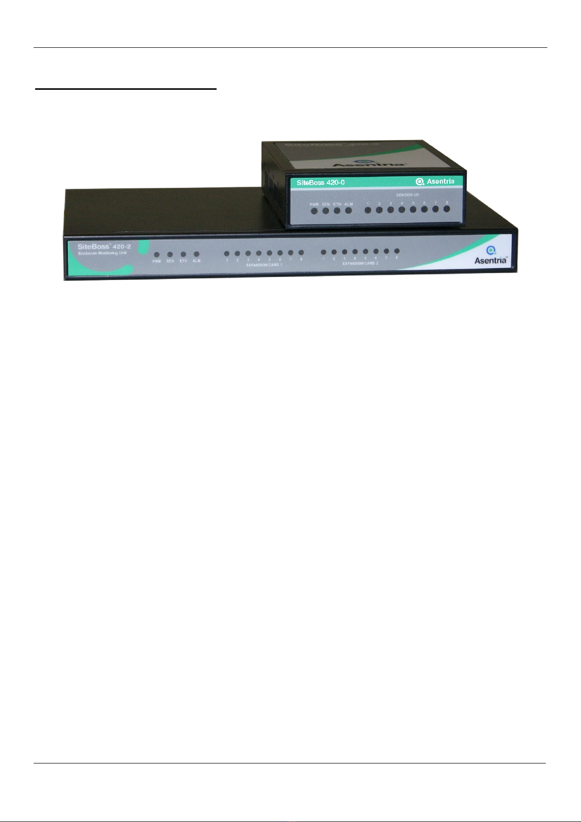
What is a SiteBoss 420..................................................................................................................3
The Basics....................................................................................................................................................................3
Communication Methods ........................................................................................................................................... 3
Event Notification ....................................................................................................................................................... 3
Parts Identification......................................................................................................................................................3
Features and Accessories ......................................................................................................................................... 3
LEDs, Ports, DIP Switches and Buttons .................................................................................................................... 4
Getting Connected.........................................................................................................................7
Power Up Sequence....................................................................................................................................................7
Default Passwords ......................................................................................................................................................7
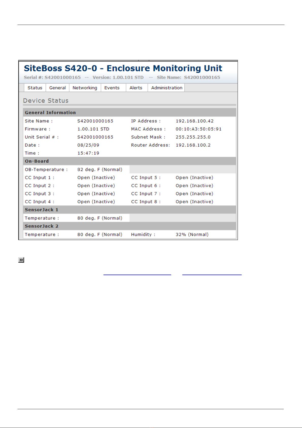
Device Status Screen..................................................................................................................................................7
Settings Tabs .................................................................................................................................8
Status............................................................................................................................................................................9
General .......................................................................................................................................................................11
Networking.................................................................................................................................................................12
Events.........................................................................................................................................................................13
On-Board Sensors ................................................................................................................................................... 13
SensorJack nSensors ............................................................................................................................................. 16
Alerts...........................................................................................................................................................................19
General Settings Tab ............................................................................................................................................... 19
Email Alerts Tab....................................................................................................................................................... 20
SNMP Alerts Tab ..................................................................................................................................................... 21
Administration ...........................................................................................................................................................22
Firmware Update ..................................................................................................................................................... 22
Reset Unit ................................................................................................................................................................ 22
Reset Parameters .................................................................................................................................................... 23
Reset ALL Parameters............................................................................................................................................. 23
Upload Settings to Unit ............................................................................................................................................ 23
Download Settings from Unit ................................................................................................................................... 23
Resetting Defaults .......................................................................................................................24
Setting Keys.................................................................................................................................25
Type2 EventSensor™ Setup.......................................................................................................28
Connections...............................................................................................................................................................28
DIP Switch Settings...................................................................................................................................................28
Configuration.............................................................................................................................................................28
Appendices...................................................................................................................................29
Canadian Department of Communications.............................................................................................................29
Warranty Information................................................................................................................................................31


Asentria SiteBoss 420 User Manual
1
Quick Start
What's Included
This chapter is a brief guide to help get your SiteBoss 420 (S420) up and running quickly.
Hardware Needed
• Asentria SiteBoss 420
• 15VDC power adaptor
• Ethernet cable
• A PC running Asentria OmniDiscover software, for purposes of assigning an IP address to the S420.
• A PC running any type of SNMP trap management software, if S420 will be sending SNMP traps as event actions.
Information Needed
• IP address to assign to the S420
• Subnet mask
• Default router IP or gateway router IP address if on a WAN (Optional)
• IP address of a PC running any type of SNMP trap management software, if S420 will be sending SNMP traps as
event actions.
Connecting
Cables and Power
1. Connect the attached ground wire securely to an appropriate earth ground (this is essential).
2. Connect an Ethernet cable into the RJ-45 jack labeled Ethernet.
3. Connect the power supply to the unit.
Power Requirements
The S420 is configured with a power jack for connecting the 15VDC power adapter shipped with the unit.
If the optional DC power option is being used, a –48VDC to AC power adapter is provided.
Accessing the unit via the Web Interface
1. Connect a network cable to the Ethernet port on the back panel of the S420.
2. Assign an IP address to the S420 using one of the following two methods:
1) Asentria OmniDiscover application – available from the Documentation and Utilities CD or the Asentria
web site: http://www.asentria.com/docsandsoftware/productManuals.aspx
a. Open the Asentria OmniDiscover application, and select Search on the top menu bar. The S420 will
be displayed in the main window including the MAC address, default Site ID, and default Subnet Mask
(255.255.255.0)
b. Right click the S420 line, and select “Setup” from the menu that appears.
c. Enter the IP Address, Subnet mask (if not default) and Gateway router address you want to assign to
the S420.
d. Press the “OK” button and you’ll be returned to the main OmniDiscover window where you should see
displayed the network address configurations you just entered.
e. Right click the S420 line again, and select “Web”. The web interface of the S420 will be displayed,
showing you the Device Status screen (as shown below). You are now connected and ready to
configure remaining settings.
2) ARP/Ping
a. From a command prompt on your PC, issue the following two commands (the S420 must have no IP
address configured for this to work):
ARP –s nnn.nnn.nnn.nnn xx-xx-xx-xx-xx-xx
Ping nnn.nnn.nnn.nnn
(where nnn.nnn.nnn.nnn is the desired IP address, and xx-xx-xx-xx-xx-xx is the MAC address)

Asentria SiteBoss 420 User Manual
b. Open your Internet browser and enter this URL: http:// < IP address of the S420>. The web
interface of the S420 will be displayed, showing you the Device Status screen (as shown below).
When the Device Status screen appears, the unit is successfully connected and ready for use.
Note: The SensorJack nsection of the Device Status screen only appears if from one to three (max) Type2
EventSensors are connected to the S420. In the example shown above, two Type2 EventSensors are connected to
the S420 and displayed. Refer to the Events/SensorJack n Sensors and Type2 EventSensor Setup sections for more
information.
2

Asentria SiteBoss 420 User Manual
What is a SiteBoss 420
The Basics
Fig 1: S420-0 (stacked on S420-2 for comparison)
The SiteBoss 420 (S420) series is a cost-effective system used for monitoring and control of remote equipment sites.
The S420 provides for remote monitoring of smaller numbers of contact closures, analog measurements, temperature
and humidity, and provides notification when conditions fall outside defined limits. The S420-0 (smaller unit shown
above) supports 8 on-board I/O points that can be ordered in various configurations, and a SensorJack port, but does
not support Expansion Cards. The S420-2 (larger unit shown above) does not have on-board I/O (other than the on-
board SensorJack) but it does provide two slots for insertion of Expansion Cards.
Communication Methods
Communication with the S420 is done solely via the web interface. The S420 has a built-in HTTP web server that is
used to configure the unit from anywhere the unit can be accessed on the network or Internet. Once you have
assigned an IP address to the unit, simply connect to http://<IP address of S420>. Secure Sockets Layer
(SSL) https://<IP address of S420> is not supported.
Event Notification
Notifications for events generated or detected within the S420 can be delivered through any of the following means:
●Email
●SNMP trap
●Relays (if S420-2 is configured with optional relay Expansion Card)
Parts Identification
Features and Accessories
Standard Equipment
The base S420 comes with the following standard on-board equipment:
• Wall mount AC power supply
• 8 Contact I/O inputs (S420-0) (see chart below for options)
• 2 – Expansion Port Slots (S420-2)
• 10/100Mb Ethernet interface
• On-board Temperature sensor (modified with external Temp Sensor cable)
• SensorJack Port
• Wall mount brackets
In addition to the above components, the standard unit is shipped with the following accessories:
• This product manual on the Documentation and Utilities CD
• RJ45 Ethernet cable
• 15VDC power supply adapter
3

Asentria SiteBoss 420 User Manual
Optional Equipment
The S420 can be ordered with the following optional equipment:
• Humidity sensor
On-board Options (S420-0 only)
All I/O is non-isolated unless otherwise indicated.
• 8 Contact Closure Inputs
• 8 CC Isolated
• 8 Low-Current Relay
• 8 Voltage Sensor
• 8 4-20mA Sensor
• 4 CC / 4 Voltage
• 4 CC / 4 4-20mA
• 4 CC / 4 Low-Current Relay
• 4 Isolated Voltage / 4 CC
• 4 Isolated 4-20mA / 4 CC
LEDs, Ports, DIP Switches and Buttons
PWRSENETHALM 12345678
SENSOR I/O
Fig 2: Front panel (S420-0)
Fig 3: Front panel (S420-2)
LEDs – Front Panel
Power
The Power LED lights green when connected to an AC power supply. During normal operation, it is steady on with a
blink every 5 seconds.
SEN (Sensor)
The SEN LED lights solid green when a Type2 EventSensor is connected to the SensorJack port on the back panel.
ETH (Ethernet)
The ETH LED lights solid green whenever an active Ethernet connection is made to the unit and flickers when TCP
packets are transmitted or received.
ALM (Alarm)
The ALM LED lights solid green to indicate that there is a sensor outside the configured alarm range. The LED will be
lit any time any of the eight Sensor I/O LEDs are lit.
Sensor I/O LEDs (S420-0 only)
The S420-0 has eight numbered Sensor I/O LEDs that indicate which of the eight contact I/O points on the back panel
is outside the configured alarm range.
4

Asentria SiteBoss 420 User Manual
Expansion Card nLEDs (S420-2 only)
The S420-2 has two expansion bays with eight numbered LEDs for each Expansion Card that indicate which of the
eight contact I/O points on each card is outside the configured alarm range.
LEDs – Back Panel
The RJ45 Ethernet port on the back panel has two LEDs associated with it – one on the Right of the port, one on the
Left.
●Right – Flashes yellow/green when network data (tcp packets) is being transmitted or received across the
port. When no data is actually being transmitted/received, this LED is off.
●Left – Lights solid green when an Ethernet cable is connected to the port and an active Ethernet network.
The LED is off when the cable is disconnected from the network, or the Ethernet Port
Fig 4: Back panel (S420-0)
The above drawing shows the S420-0 configured (from right to left) with AC power jack, Reset button, bank of 4 DIP
switches, one RJ45 10/100 Ethernet port, one SensorJack port, and 8 pairs of contact I/O inputs which can be ordered
in various configurations. The S420-2 (available later in 2009) will include two expansion card slots for use with
optional Expansion Cards*.
Note: The on-board temperature sensor is located inside the S420 case but it tends to read higher than normal
due to internal heat. An external temperature cable is provided for reading a temperature in very close proximity to
the S420 that is more accurate.
Ports
Ethernet
The Ethernet 10/100Mb interface is standard RJ45 that allows connection to an Ethernet hub or switch. LEDs by the
Ethernet port on the back panel flicker when packets are being transmitted/received on that port.
Sensor Jack
The Sensor Jack port is a 9-pin Mini DIN connector for connecting up to three optional Type2 EventSensor devices.
Contact I/O Inputs
These eight pairs of contacts are standard contact inputs by default, but internally can be enhanced, when ordered, to
be voltage, relays, current (4-20mA), isolated voltage, isolated current, or isolated contacts.
5

Asentria SiteBoss 420 User Manual
6
DIP Switches
The four DIP switches on the back panel of the S420 are not currently used during normal operation. All four DIP
switches are shipped from the factory in the UP position, and should remain that way. If all four are set to the DOWN
position and the Reset button is briefly pressed, all the internal settings will be returned to default.
Buttons
The only button on the S420 is the Reset button located on the back panel to the right of the DIP switches. When
pressed it will cause an immediate reset of the S420. All configurations are preserved when the unit is reset.
* Expansion Cards
The S420-2 will feature two Expansion Card slots in which optional Expansion Cards can be installed to expand the
capabilities of the S420. Contact Asentria Sales (sal[email protected]) for more information on the S420-2 and
Expansion Cards.

Asentria SiteBoss 420 User Manual
7
Getting Connected
Power Up Sequence
When power is applied, the S420 boots up immediately. The PWR LED lights and begins to blink once every 5
seconds, and will do this continuously as a “heartbeat” while the S420 is powered on.
Default Passwords
S420 firmware version 1.00.000 did not utilize any form of password security. With version 1.00.101 a Username and
Password (basic authentication without a secure connection) are required. Default login credentials are
admin/password but these can be changed on the Networking Settings screen.
Three attempts are allowed to enter the correct login credentials. After the third incorrect entry, the login window is no
longer displayed, leaving the user with a blank browser screen. Refresh the browser to make the login window
reappear, then try again. If needed, the default Username and Password can be set using the DIP switches as
described in the Resetting Defaults section.
Device Status Screen
The Status tab displays the Device Status screen, which is this unit's one-stop informational source. Much of the
information that a user would need to know about the unit is available through this display. Refer to the Status tab
section for a detailed description of all the information available on this screen.

Asentria SiteBoss 420 User Manual
Settings Tabs
The S420 web interface provides 6 tabs across the top of the main screen that allows access to different settings that
can be configured by the user. This section describes each of these tabs and the settings they contain.
Status – displays the Device Status screen where current data about the S420 is displayed. This screen is
informational only, with no user configurable settings.
General – displays the General Settings screen where Site Name, Current Date & Time, and Daylight Savings
Time adjustment can be configured.
Networking – displays the Networking Settings screen where IP Address, Subnet Mask, Router Address, SNMP
Community names, and login credentials can be configured.
Events – displays Events Settings sub-tabs for configuring the On-Board Sensors (internal Temp Sensor and
internal contacts (S420-0 only), connected Type2 EventSensors, as well as Expansion Cards (S420-2 only).
Alerts – displays the Alert Settings screen where general alert settings, as well as specific Email and SNMP alert
settings can be configured.
Administration – displays the Administration Settings screen where general administrative functions for the unit
can be conducted. These include uploading a new firmware file, resetting the unit, resetting all parameters to their
default settings, and uploading/download the Setting Keys file.
At the bottom of each screen where settings can be configured are a Submit button and a Cancel Changes button. If
you make changes and are satisfied with them, press the Submit button. New configurations will be applied
immediately. Press the Cancel Changes button before pressing the Submit button to reset any configuration changes
to what they were previously.
Note: Take care when making changes to Network Settings. Because these take effect immediately, you will lose
your network connection to the S420 and have to reconnect using the new configurations.
8

Asentria SiteBoss 420 User Manual
Status
General Information
Site Name – is the identifier assigned to each S420, and is configured in the Site Name field on the General tab.
Default setting is: S420-0 <serial number>.
Firmware – indicates the currently loaded firmware version.
Unit Serial # - is the factory-assigned, unique serial number for this S420.
Date and Time – display the current date and time. Date and Time can be set on the General tab.
IP Address – is the network IP address assigned to this S420.
MAC Address – is the hard-coded MAC Address of the Ethernet interface in this S420. The MAC address can also
be found on the unit’s serial number label. The MAC address cannot be changed and is displayed for informational
purposes.
Subnet Mask – is the subnet mask, which should be provided by your network administrator.
Router Address – is the IP address of the network gateway or router to which this S420 is connected. Your network
administrator should provide the gateway or router address to you.
9

Asentria SiteBoss 420 User Manual
Note: IP Address, Subnet Mask, and Router Address are all user-configurable on the Networking tab.
On-Board
OB-Temperature displays the current reading of the on-board temperature sensor. This can be set to read in
Fahrenheit or Celsius on the Events/On-Board Sensors tab.
CC Input ndisplays the current Open/Closed and Active/Inactive status of each of the 8 on-board contact closures.
SensorJack n
The S420-0 currently supports three Type2 EventSensors that monitor either Temperature (ES-T) or Temperature and
Humidity (ES-TH). If one or more of these types of Sensor’s is connected, this section will be displayed with the
current reading(s). If no Sensors are connected, this section will not be displayed. Refer to the Type2 EventSensor
section for more information.
10

Asentria SiteBoss 420 User Manual
General
Site Name – sets the identifier assigned to each S420, and is displayed on the Device Status screen. Default setting
is: S420-0 <serial number>. (Max length 40 chars)
Current Date / Time – displays the current Date and Time. The Set Date/Time button provides a pop-up window
where the date and the time can be reset.
Adjust for DST – provides a drop down menu where the Daylight Savings Time function can be turned On or Off.
Default setting is On.
• A brief explanation of daylight savings time (effective 2007): On the second Sunday in March, clocks are set
ahead one hour at 2:00 a.m. local standard time, which becomes 3:00 a.m. local daylight time. On the first
Sunday in November, clocks are set back one hour at 2:00 a.m. local daylight time, which becomes 1:00 a.m.
local standard time.
Note: The date and time settings are maintained by means of an internal battery backup when power is removed
from the S420.
11

Asentria SiteBoss 420 User Manual
Networking
IP Address – sets the network IP address assigned to this S420. Default setting is 0.0.0.0
MAC Address – is the hard-coded MAC Address of the Ethernet interface in this S420. The MAC address can also
be found on the unit’s serial number label. The MAC address cannot be changed and is displayed for informational
purposes.
Subnet Mask – sets the network subnet mask provided by the network administrator. Default setting is
255.255.255.0
Router Address – sets the router address provided by the network administrator. Default setting is 0.0.0.0
SNMP Trap / Read / Write Community – sets the SNMP trap community name to use for each. Default setting for
each is “public”. (Currently the S420 does not support SNMP “gets” and “sets”, so the Read and Write Community
names are not used.)
Web Login Username / Password – sets the login credentials required by the web interface. Default setting is
Username: admin and Password: password. The password is always masked. For security reasons it is highly
recommended that you change this password, and record all configured passwords in a secure location. If locked out
of the S420-0 because the password has been forgotten, it is possible to reset the unit to its default login credentials.
Refer to the Resetting Defaults section in this manual.
Note: Take care when making changes to Networking Settings. Because these are made immediately you will
lose your network connection to the S420 and have to reconnect using the new configurations.
12

Asentria SiteBoss 420 User Manual
Events
Rolling over the Events tab will display a drop down menu for On-Board Sensors and SensorJack n Sensors (if
optional Type2 EventSensors are connected). Select either of these menu options to display those configuration
screens as shown and described below.
Note: Because the initial release of the S420-0 has 8 internal dry contact closure points, those are displayed and
described below. Other options for different I/O through these contact points (voltage, current, relay output) will be
available at a later date in a future version. The S420-2, which features two Expansion bays for a variety of
Expansion Card options, will be displayed and described in a future version of the S420 User Manual.
On-Board Sensors
Temp Sensor Tab
Alarm Name – sets the name of the alarm that is generated when the temperature rises above or drops below the set
thresholds. This name is included in the Email and/or the SNMP Trap generated. Default setting is OB-Temperature.
(Max length 32 chars)
Currently – displays the current temperature.
Units – sets the unit to report temperature in either Fahrenheit or Celsius.
Alarm State – is an On/Off toggle to set whether the S420 should take an alarm action if the current temperature
exceeds any of the Very High / High / Low / Very Low thresholds shown to the right. Default setting is Off.
13

Asentria SiteBoss 420 User Manual
Alarm Actions – sets the action(s) to be taken if Alarm State is set to ON, and the temperature exceeds any of the
Very High / High / Low / Very Low thresholds shown to the right. Alarm Actions are configured as Enwhere n
corresponds to the Email Address index number on the Email Alerts tab, and Tnwhere ncorresponds to the SNMP
Manager index number on the SNMP Alerts tab. Multiple actions are listed with no delimiters, so for example:
T1T2E2E3 would send a trap to SNMP Managers 1 and 2, and an Email message to Email Addresses 2 and 3.
Deadband – sets the range, in degrees, on either side of a temperature setting that prevents the event from
repeatedly going in and out of the "event state" as the actual temperature fluctuates above and below the temperature
setting. Default setting is 3 degrees.
Very High / High / Low / Very Low Temp – are the settings for each of four temperature thresholds that the S420
can alarm on. If Alarm State is set to ON, and the temperature rises above the High and Very High settings, the Alarm
Actions will take effect. Same process if the temperature drops below either the Low or Very Low settings. Default
settings are: Very High (120), High (100), Low (40), Very Low (32).
Very High / High / Low / Very Low Severity – displays a drop down menu of four descriptive words – Info, Minor,
Major, Critical – that allow you to assign a severity rating to this alarm. This word will appear in an SNMP Trap alert,
but does not appear in an Email alert. Default setting for all is “Info”.
Contacts Tabs (S420-0 only)
Displays contacts 1 thru 4 or 5 thru 8 depending on which tab is selected.
14

Asentria SiteBoss 420 User Manual
15
Contact Name – is an alphanumeric field that allows you to name this contact closure. (Max length 32 chars)
Currently – displays the current state of the contact – Open or Closed.
Alarm State – is an On/Off toggle to enable or disable the alarm for this contact. Default is Off.
Alarm Actions – sets the action(s) to be taken if Alarm State is set to ON, and the contact goes into the active state.
Alarm Actions are configured as Enwhere ncorresponds to the Email Address index number on the Email Alerts tab,
and Tnwhere ncorresponds to the SNMP Manager index number on the SNMP Alerts tab. Multiple actions are listed
with no delimiters, so for example: T1T2E2E3 would send a trap to SNMP Managers 1 and 2, and an Email message
to Email Addresses 2 and 3.
Active State – is an Open/Closed toggle that sets whether an alert will be triggered when the contact closure circuit is
opened or closed. The default state is Closed.
Severity – displays a drop down menu of four descriptive words – Info, Minor, Major, Critical – that allow you to assign
a severity rating to this alarm. This word will appear in an SNMP Trap alert, but does not appear in an Email alert.
Default setting for all is “Info”.
Threshold – sets the number of seconds (0-255) the contact must remain in the Active State before the Alarm Action
is triggered. Default setting is 2 seconds.
Active Alias – sets a special name used when the contact goes into its Active State and an alert is sent. (Max length
16 chars)
Inactive Alias – sets a special name used when the contact returns to its Inactive State, and a Return to Normal
alerts is sent (if Send Return to Normal Alerts is enabled on the Alerts tab.) (Max length 16 chars)

Asentria SiteBoss 420 User Manual
SensorJack nSensors
Each SensorJack nSensors screen will have tabs for the various types of sensors that each Type2 EventSensor
supports. Currently, only the Temperature (ES-T) and Temperature and Humidity (ES-TH) Type 2 EventSensors are
supported by the S420. The configuration screen for the ES-TH is shown below. For more information about Type2
EventSensors, please refer to that section in this manual.
Temp Sensor
Alarm Name – sets the name of the alarm that is generated when the temperature rises above or drops below the set
thresholds. This name is included in the Email and/or the SNMP Trap generated. (Max length 32 chars)
Currently – displays the current temperature.
Units – sets the unit to report temperature in either Fahrenheit or Celsius.
Alarm State – is an On/Off toggle to set whether the S420 should take an alarm action if the current temperature
exceeds any of the Very High / High / Low / Very Low thresholds shown to the right. Default setting is Off.
Alarm Actions – sets the action(s) to be taken if Alarm State is set to ON, and the temperature exceeds any of the
Very High / High / Low / Very Low thresholds shown to the right. Alarm Actions are configured as Enwhere n
corresponds to the Email Address index number on the Email Alerts tab, and Tnwhere ncorresponds to the SNMP
Manager index number on the SNMP Alerts tab. Multiple actions are listed with no delimiters, so for example:
T1T2E2E3 would send a trap to SNMP Managers 1 and 2, and an Email message to Email Addresses 2 and 3.
16
Table of contents
Other Asentria Remote Control manuals
Popular Remote Control manuals by other brands

nedis
nedis WIFILR001BK quick start guide

GRAUPNER
GRAUPNER mz-24 PRO Programming manual

Sony
Sony RM-US104 manual

Lutron Electronics
Lutron Electronics Spacer System SPS-FSIT operating instructions

Gimson Robotics
Gimson Robotics GLA-CU-X2 Setup guide

Waeco
Waeco MagicTouch MT200 Installation and operating manual