Ask DFS-1 User manual

PB97001E-A
2011/06/28
1
INSTRUCTION MANUAL
FOR
DIGITAL FLOW SENSOR
〔DFS-*-O/W〕
Contents
1. Preface
2. Safety precautions
3. Installation tips
4. Necessary considerations
5. Description of Model-No.
6. Wiring connection
7. Explanation of function
8. How to configure
9. How to remove a contaminant
10. Specifications
ASK CORPORATION
1-34-16, Higashi-Shinagawa, Shinagawa, Tokyo,
140-0002, Japan.
Tel: 03-3471-4845 Fax : 03-5463-7022
Branch: Osaka
Read the Instruction Manual
昆山瑞腾精密自动化有限司
昆山瑞腾精密自动化有限司

DFS-*-O/W
2
1. Preface
For best results, please refer to this manual before using this product.
2. Safety precautions
Model
Precautions
DFS-1
The maximum pressure of this model is 3 MPa (30 bar). Do not exceed
this maximum pressure rating. Doing so may cause the sensor to
explode and result in possible physical injury.
DFS-2
DFS-3
DFS-6
DFS-8
(1) Before using these sensors, Select and install an appropriate cap on the
center of the body, as follows:
▪If the maximum pressure for the sensor exceeds 3 MPa (30 bar) and the
flow sight function is not necessary, an all-metal cap must be installed.
▪If the maximum pressure is lower than 3 MPa (30 bar) and the flow
sight function is necessary, a metal/plastic cap can be used.
(2) Be sure to use the sensor within its maximum pressure.
Do not exceed this maximum pressure rating. Doing so may cause the
sensor to explode and result in possible physical injury. Refer to Section
10 for the specifications for your particular model.
All Models
(1) When carrying the sensor, handle only the metal portion. Do not
handle the black amplifier box portion.
(2) Test the sensor after it is connected to the power supply and initialized.
(3) Configure the output type (NPN or PNP) after you check the wiring
connection. The factory setting is NPN output.
(4) Employ a shielded cable if you are using this sensor near a power
source that is generating strong electrical noise.
昆山瑞腾精密自动化有限司
昆山瑞腾精密自动化有限司

DFS-*-O/W
3
3. Installation tips
(1) Before installing the sensor, flush all piping passages clean.
(2) For accuracy, provide straight piping of more than 10 times the inner diameter of the pipe
on the upstream side, and more than 4 times on the downstream side. Do not install curved,
confluence, or branch piping (, that is, elbow, tee, throttle valve ), near the outlet.
Model
Upper Flow Passage
Lower Flow Passage
DFS-1
> 100 mm
> 40 mm
DFS-2
> 140 mm
> 60 mm
DFS-3
> 170 mm
> 70 mm
DFS-6
> 270 mm
> 110 mm
DFS-8
> 340 mm
> 140 mm
(3) The sensor does not have a dedicated “in port”and “out port”. Therefore, you can use either
port for connecting the in-flow and out-flow pipes.
(4) When connecting pipes, avoid torqueing, bending, or applying any unnecessary load to any
portion of the sensor except for the hexagonal part on either end.
Ensure that the piping is properly supported. Do not remove the amplifier box from the
body.
(5) Avoid operating the sensor near areas containing a strong magnetic field or static electricity.
Doing so may cause the sensor to malfunction.
4. Necessary considerations
(1) Be sure to use the sensor within the maximum flow rate for your model. Exceeding the
flow rate may shorten the life of this sensor or cause damage.
(2) Be sure that the fluid flowing through the sensor is clean, or install a “filter”to prevent
clogging.
(3) Avoid using the sensor with fluids that contain magnetic materials; the sensor contains a
permanent magnet, and magnetic materials in the fluid may cause the sensor to
malfunction.
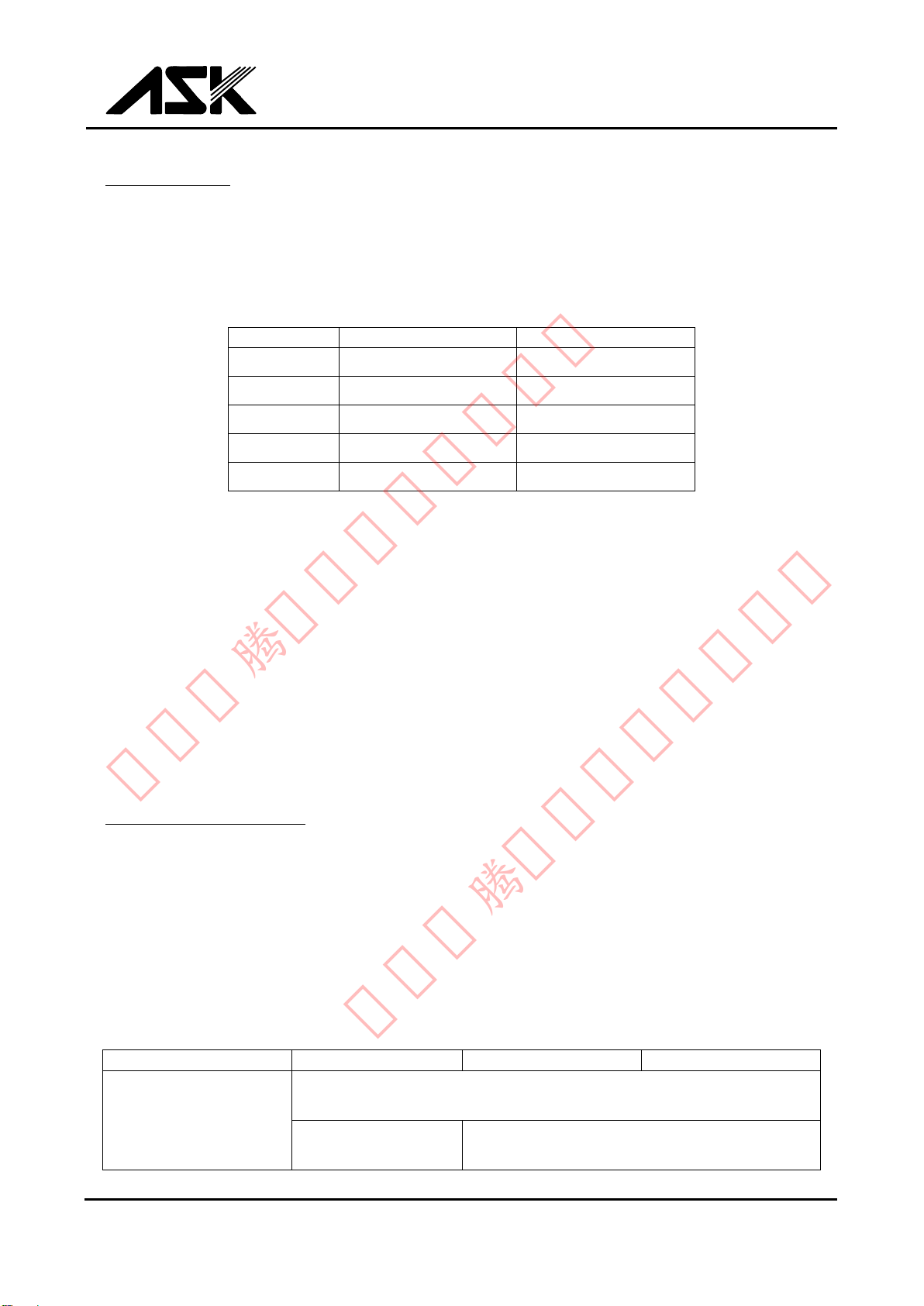
Recommended Filtration Element and Available Fluid
Model
DFS-1
DFS-2, 3, 6
DFS-8
Available Fluid
(Filter Element)
Hydraulic oil, Lubricating oil
(5~20 μm)
--------
Water, Water-soluble cutting oil
(20~50 μm)
昆山瑞腾精密自动化有限司
昆山瑞腾精密自动化有限司

DFS-*-O/W
4
5. Description of Model-No.
EXAMPLE
DFS
-
2
-
O
-
*
①
②
③
④
①DIGITAL FLOW SENSOR
②NOMINAL SIZE (Connection thread)
1: Rc 1/8
2: Rc 1/4
3: Rc 3/8
6: Rc 3/4
8: Rc 1
③FLOW MEDIUM
O: Hydraulic oil, Lubricating oil
W: Water, Water-soluble cutting oil
④CUSTOM SPECIFICATIONS
Please ask us.
6. Wiring connection
M12x1 4-pin connector
①(+)POWER SOURCE:
DC +12~24 V (allowable oscillation ±10 %)
②UNUSED
③(-)DC 0 V
④OUTPUT:NPN (factory setting) or PNP
昆山瑞腾精密自动化有限司
昆山瑞腾精密自动化有限司

DFS-*-O/W
5
7. Explanation of function
Flow rate measurement
The sensor initialized for 7 seconds after it is connected to a power supply. You can start using
the sensor to measure flow after the sensor completes this initialization period.
A seven-segment LED display indicates the flow rate. If the flow rate drops below the lower
limit or exceeds the upper limit of the specified range, the LED blinks 「---」.
EXAMPLE : DFS-2-O
Configuring the output (alarm)
You can configure the output (alarm) within use flow rate range. The relation of flow rate,
adjusted value, LED indications, and the output is shown below.
For details, see Section 8.
Flow Rate
Less than Adjusted Value
More than Adjusted Value
LED(RED)
ON
OFF
LED(GREEN)
OFF
ON
Configuring the display
You can select non-display mode. If you do so, the LED display indicates「---」.
For details, see Section 8.
Configuring the output type
You can configure the output type after you check the wiring connection.
(The factory setting is NPN)
PNP
NPN
1~10 L/min
Low flow rate below 1 L/min
High flow rate above 10 L/min
BLINK
BLINK
LOAD
LOAD
D
F
S
D
F
S
昆山瑞腾精密自动化有限司
昆山瑞腾精密自动化有限司

DFS-*-O/W
6
8. How to configure
Alarm
Display
Display
※If you pause more than 30 seconds in a configuration mode, the flow rate value would be
displayed.
Press and hold for 2 seconds to switch modes.
Press to select one of 4 headings within a configuration mode.
(Alarm, Display, Output type or Cancel)
Switch to output/alarm mode.
Configure Output/Alarm
Press to select a value.
Hold to scroll through the numbers quickly.
For decision/ Switch to measuring flow rate.
(*Configure a value within use flow rate range)
Configure Display
Switch to display mode.
For select
For decision/ Switch to measuring flow rate
Non-display
Switch to output type mode.
Press to select output type ( NPN or PNP).
NPN
PNP
For decision
Practice
Cancel
Configure Output Type
For decision
Cancel
Press to cancel.
昆山瑞腾精密自动化有限司
昆山瑞腾精密自动化有限司

DFS-*-O/W
7
9. How to remove a contaminant
You can remove a contaminant from the magnet of the rotor by blowing air. You do not need
to disconnect the piping from the sensor before performing this procedure.
(1) Remove the cap installed on the center of the body (see below).
(2) Using an air blower, blow out the contaminant toward the downstream side of the sensor.
(3) Re-install the cap using the recommended tightening torque below.
Recommended Tightening Torque.
For
Metal/ Plastic Cap
100 kgf-cm (10 N-cm)
All-Metal Cap
100 kgf-cm (10 N-cm)
O-RING
BODY
CAP
昆山瑞腾精密自动化有限司
昆山瑞腾精密自动化有限司

DFS-*-O/W
8
10. Specifications
General Specification
DFS-1
DFS-2
DFS-3
DFS-6
DFS-8
CONNECTING
THREAD
Rc 1/8
Rc 1/4
Rc 3/8
Rc 3/4
Rc 1
MAXIMUM FLOW
RATE (L/min)
1
10
20
50
100
MEASUREMENT
RANGE
(L/min)
0.2~1
1~10
2~20
5~50
10~100
MAXIMUM
PRESSURE (MPa)
3
3 (if a metal/plastic cap is installed)
25(if an all-metal cap is installed)
FLOW SIGHT
FUNCTION
Available
Available
(if a metal/plastic cap is installed.)
Not available
(if an all-metal cap is installed.)
ACCURACY (L/min)
±0.1
±0.5
±1
±2.5
±5
FLUID
(※1)
O
O, W
PRESSURE LOSS
(MPa ※2)
> 0.03
> 0.025
TEMPERATURE
0~80 ℃(Fluid) 0~50 ℃(Ambient temperature)
MATERIALS
(FLUID CONTACT
PARTS)
C3604 (Ni Plaiting), Nd-Fe-B (Ni Plaiting)
POM, PC(plastic/metal cap only), NBR
※1: O/ Hydraulic oil, Lubrication oil W/ Water, Water-soluble cutting oil
We adjust each type of sensors at our factory in accordance with fluid type. Please
specify the type of fluid you intend to use the sensor with when you place your order.
※2: Value for Maximum. Flow Rate at viscosity 32 cSt.
Amplifier Specification (All Models)
POWER SOURCE
DC 12~24 V
CURRENT CONSUMPTION
Maximum. 100 mA
OUTPUT
NPN open collector (factory setting)
PNP open collector (maximum. load 100mA)
(This setting is optional.)
CONNECTION
M12×1-4-pin connector (DC)
DEGREE OF PROTECTION
IP67 equivalent
AMBIENT TEMPERATURE
Surrounding/0~50 ℃
MATERIALS (OUTSIDE)
ABS, POLYESTER, NBR, and PA
昆山瑞腾精密自动化有限司
昆山瑞腾精密自动化有限司
This manual suits for next models
4
Table of contents