Asko TD75 User manual

INSTALLATION INSTRUCTIONS
TD75
Carefully read the instructions for use before using the dryer.
Vented tumble dryer
DOMESTIC

2Customer Care Center, 1-800-898-1879, www.askousa.com
INSTALLATION
WARNING - Risk of fire.
Install the clothes dryer according to the
manufacturer's instructions and local codes.
Do not install a clothes dryer with flexible plastic
venting materials. If flexible metal (foil type) duct is
installed, it must be of a specific type identified by
the applience manufacturer that is UL approved for
use with clothes dryers. Flexible venting materials
are known to collapse, be easily crushed, and trap
lint. These conditions will obstruct clothes dryer
airflow and increase the risk of fire.
To reduce the risk of of severe injury or death, follow
all installation instructions.
SAVE THESE INSTRUCTIONS FOR FUTURE
REFERENCE.
DRYER PLACEMENT
The dryer can be either free standing or installed onto
a washing machine.
The dryer emits heat. Therefore, do not place it in a
very small room, as the drying process may be longer
due to limited amount of available air.
Do not place the dryer in a room where
temperature can drop below 0 °C, as the machine
may not operate correctly at such low temperatures,
or freeze, which in turn can result in damage to the
machine.
Install the dryer in a room with adequate ventilation and
a temperature between 15 °C and 25 °C.
Do not place the dryer behind lockable or sliding
door, or door with a hinge on the opposite side of the
dryer door hinge. Install the dryer in such way that the
door can always be freely opened.
Never block the air exhaust (evacuation opening).
At least two persons are required to install the
tumble dryer on top of a washing machine.
Do not place the dryer on a carpet with long fibres
as this may impede air circulation.
The appliance may not be in contact with a wall
or adjacent furniture. For optimum dryer operation,
observe the clearance from the wall as shown in Fig.
Dear Customer,
Read these instructions carefully and completely before you install the machine. The installation should
be carried out by a qualified person who is familiar with all local codes and ordinances for electrical and
plumbing connections. See also the general Safety Instructions in the Use & Care Guide.
Cosmetic damage must be reported to the ASKO dealer within five days from the date of purchase. As soon
as you unpack the machine, thoroughly check it for cosmetic damage.

3
Customer Care Center, 1-800-898-1879, www.askousa.com
Free-standing appliance
The dryer may be placed adjacent to a washing
machine.
If the friction between the dryer feet and the floor is not
sufficient, the dryer may move during operation. To
prevent the dryer from sliding around, use a non-slip
support or pad.
Clearance between the dryer and the wall
50 mm
100 mm
100 mm
Opening the dryer door (top view)
480 mm
1074 mm
176°
Stacking on top of a washing machine
To stack the dryer on top of a washing machine, use
the extra vacuum feet and the tipping guard (A+B),
supplied in the cardboard box in the dryer drum.
Tipping guard part B is designed to fit on ASKO
washing machines and it may be hard or impossible
to mount on appliances of other brands. If the
washing machine and dryer are not of matching
dimensions or if you have installed a hidden helper
between the two appliances, then binding plates
are available as optional accessories at the service
unit (… available only for HH and TD75 stacked on
top of WM80 or WM85; not intended for any other
combinations).
AB
All ASKO washing machines can bear the weight of
the dryer.
Washing machine on which you wish to install
the dryer must be able to bear the weight of the dryer
(see washing machine’s rating plate or technical
information).

4Customer Care Center, 1-800-898-1879, www.askousa.com
How to stack a dryer onto the washing machine (ASKO):
There is a cardboard box in the dryer drum, containing the vacuum feet and the tipping guard.
A B
1The tipping guard consists of two metal parts (A +
B).
Use two screws to attach the A part to the back of the
dryer.
2Undo the screw on the back side of the washing
machine.
3Use the screw to attach the tipping guard (B part)
to the back of the washing machine.
1
2
3
4Level the washing machine so that it is stable.
1. Level the washing machine in longitudinal and
traverse direction by rotating the adjustable feet
using a No. 32 spanner.
The feet allow levelling by +/- 1 cm.
2. After adjusting the height of the feet, firmly
tighten the jam nuts (counter nuts) using a
spanner No 17, by turning them towards the
bottom of the washing machine .
3. Tighten the jam nuts (counter nuts).
5 mm
1
2
5Set the dryer feet:
1. Tighten the front two feet all the way in.
2. Undo the back feet by 3.5 turns or 5 mm; then,
fasten the jam nuts towards the bottom of the
appliance .
13
2
6Place the dryer onto the washing machine:
1. Lift the front part of the dryer by 5 to 10 cm.
2. Attach the vacuum feet onto the front feet of the
dryer.
3. Push the dryer into the tipping guard (so that
the B part is inserted into the A part) and
release it (See figure on previous page).
Make sure the tipping guard is "locked"!

5
Customer Care Center, 1-800-898-1879, www.askousa.com
CHANGING THE DOOR OPENING DIRECTION
To change the direction of door opening, proceed as follows.
1Open the door fully.
2Undo the screws and remove the door.
3Use the screwdriver to remove the door lock cover
and undo the screw on the door lock.
4Push the door lock upwards and remove it. Move
it to the other side and push it downwards.
5Fasten the screw on the door lock. Replace the
door lock cover.

6Customer Care Center, 1-800-898-1879, www.askousa.com
6Undo the door hinge assembly (left) and the door
latch assembly (right), switch their positions, and
replace the screws (door hinge assembly to the right-
hand side, door latch assembly to the left-hand side).
Use the screwdriver to remove the plastic part
more easily.
7Undo the door ring and remove it temporarily.
8Rotate the door glass cover by 90°so that the sign
indicating the opening of the door is on the other
side.
9Rotate the door ring by 180°, install it onto the
door, and fasten it with screws.
10 Replace the door on the door hinge and fasten
the screws.

7
Customer Care Center, 1-800-898-1879, www.askousa.com
BUILT-IN
ASKO dryers can be installed beneath a cabinet
or worktop with a minimum height of 34” (864mm).
There must be a gap of about 1/2” (12mm) all around
the machine, including between the rear edge of the
machine and the back wall. The opening width must
be at least 24-1/2” (622 mm).
The height adjustment for the dryer is 33-1/2” to
34-1/2” (850 mm to 876 mm). Do not raise it higher
than 34-1/2” (876 mm). Hole measurements are from
center of hole.
Install in a closet
ASKO's front panel controls make it possible to
install the washers and dryers in a closet. Make
sure there is a ½” (12mm) minimum clearance
between units and cabinet or wall. To ensure
proper ventilation, we recommend louvered doors.
Otherwise there must be ventilation openings in
the door. See illustration for minimum ventilation
openings:
Ensure the dryer door can be opened without
hindrance after installation.
The cool air intake panel at the front of the dryer
must not be blocked or covered. Doing so could
cause a fault.

8Customer Care Center, 1-800-898-1879, www.askousa.com
AIR EXHAUST
The tumble dryer must only be operated when it
is correctly fitted with exhaust duct.
Connecting the exhaust duct to the dryer
You will need to purchase a UL-CSA-approved
4" ridged metal exhaust duct. The dryer is delivered
with the stub pipe attached to the rear exhaust
outlet, though the exhaust duct can be attached to
either the left or the right exhaust outlet.
Asko dryers have a "T-style" exhaust
vent that allows you to connect the duct
on the rear, on the left, or on the right
side Vent
Stub Duct
Clamp
(not supplied)
T-tube
Rear Exhaust
Outlet
Side Exhaust
Outlet
The duct must not be assembled with screws or
other fasteners that extend into the duct and catch
lint.
To connect the exhaust duct to the rear outlet
To connect the exhaust duct to the rear outlet, follow
the steps below:
1. Push the duct onto the stub pipe and secure it
with a clamp
2. With the duct attached, insert the stub pipe into
the hole. It should snap into place.
3. After you push the dryer into place, check for
kinks in the duct.
Excessive duct length and too many bends can
impede drying performance. We recommend that
you cut offany excess exhaust duct and run the duct
with as few bends as possible. Make any necessary
bends as gentle as possible.
Maximum duct length of 60 feet. A maximum
of 4 elbows may be used, but 4 feet of duct must
subtracted from the total vent length for every 90°
elbow used.
Connecting the exhaust duct to the Left or Right
Side Outlet
To connect the exhaust duct to the left or right side
outlet, follow the steps below:
1. Using a flathead screw-driver, turn the exhaust
outlet cover you plan to use to the right or left to
align the tabs holding the cover in place.
2. Remove the exhaust outlet cover.
3. Remove the stub pipe from the rear exhaust outlet
and place it in the outlet you plan to use.
4. Push the duct (3) onto the stub pipe (1) and
secure it with a clamp (2).
5. With the duct attached, insert the stub pipe into
the hole. It should snap into place.
6. After you push the dryer into place, check for
kinks in the duct.
7. Use the exhaust outlet cover you removed from
the to cover the rear exhaust outlet.
123
123

9
Customer Care Center, 1-800-898-1879, www.askousa.com
To reduce the risk of fire, this appliance must
be exhausted OUTDOORS or the equivalent. Never
cover the end of the dryer stub or exhaust duct with
anything to catch lint, except for UL approved vent
basket.
Connecting to a ventilation duct
You will need a UL-CSA-approved, 4-inch ridged
metal exhaust duct. If a flexible duct is used, it must
comply with the Outline for Clothes Dryer Transition
Duct. Subject 2158A and maximum length of 2.4 m
(8 feet).
The more bends and the longer the duct, the
less air will circulate through the machine, which
will impede drying performance. We recommend
that you cut offany excess exhaust duct and run the
duct with as few bends as possible. And make any
necessary bends as gentle as possible.
Maximum duct length of 60 feet. A maximum
of 4 elbows may be used, but 4 feet of duct must
subtracted from the total vent length for every 90°
elbow used.
When installing in warm climates (77° F and
above) with high humidity levels, do not route the air
exhaust duct upwards.
Examples of installations
subtract 4 feet for
every 90° elbow
To connect the exhaust duct to a ventilation
outlet, follow the steps below:
1. Connect the exhaust duct to a ventilation exhaust
fitting or to a discharge through the wall.
2. Secure the duct joint to the outlet stub on the
machine.
3. Run the duct with as few bends as possible to the
point of discharge.
Ventilation grill (not
supplied with machine)
This appliance shall not be exhausted into a
chimney, a wall, a ceiling, an attic, a crawl space
or a concealed space of a building. Only a rigid or
flexible metal duct shall be used for exhausting. Only
a metal ventilation grill shall be used. If the duct is
taken to a wall outlet, a ventilation grill shall be fitted
to prevent reverse flow of cold air. Fit the ventilation
grill to the outside of the wall.
Avoid:
• very long exhausting systems
• too many corners
• tight corners
These reduce efficiency and increase time and
energy consumption.

10 Customer Care Center, 1-800-898-1879, www.askousa.com
ELECTRICAL INSTALLATION
The receptacle on the rear of the machine is
designed to accommodate ASKO washers ONLY
(rated 208–240 V.) To use this receptacle, you must
use the ready-fitted plug supplied with the washing
machine or an equivalent.
ASKO washers rated 208–240 V have two internal
fuses of 15 A each.
The machine should only be connected to a
grounded wall socket.
This appliance must be properly grounded.
Refer to the “Important Safety Instructions” for
grounding instructions.
The power supply cord must be grounded. If the
machine is to be used in a wet area, the supply must
be protected by a residual current device.
Connection to a permanently wired supply point
must be made only by a qualified electrician. As
supplied: Single-phase, 208–240 V, 60 Hz, 3000W
heater rating 15 A circuit required.
Do not connect the machine to the mains
electricity supply by an extension lead.
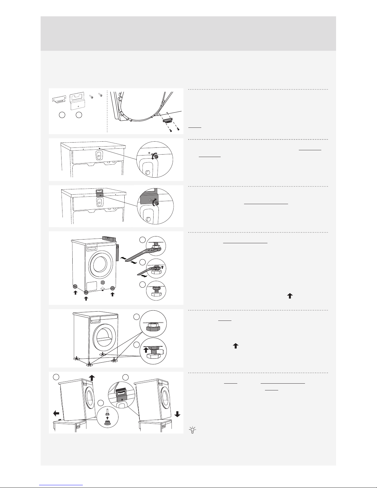
Remove cover to access terminal box.
(Requires a 20-Torx screwdriver.)
Electrical Connections
Read the Electrical requirements and grounding
instructions before connecting the tumble dryer.
Electric models of the dryer are manufactured for
a 3-wire connection system. The dryer frame is
grounded by a link to the neutral conductor on the
dryer terminal block. If local codes do not permit
grounding through the neutral, the grounding link
from the terminal block must be removed and a
separate ground wire must be used.
Only a 4-conductor cord shall be used when the
appliance is installed in a location where grounding
through the neutral conductor is prohibited.
Grounding through the neutral conductor is
prohibited for new branch-circuit installations,
mobile homes, recreational vehicles, and areas
where local codes prohibit grounding through the
neutral conductors. The grounding link on the dryer
must be removed for all 4-wire installations.
These Electrical Connection instructions provide for
installing the dryer in the following situations:
3-wire connection where local codes permit
grounding through the neutral. 3-wire connection
plus separate grounding connector where local
codes do not permit grounding through the neutral.
4-wire connection.
Each of the above connections can be made
with an approved power supply cord or by direct
wiring. Each connection instruction identifies
the appropriate Power Supply Cord and covers
requirements for direct wiring.
In Canada, the dryer is delivered ready-fitted
with a four-prong plug intended for connection to a
single-phase supply.
Connecting a 3-wire Power Cord
Before starting this procedure, be sure the
power is turned offat the breaker/fuse box.
Spade terminals
with upturned
ends
Ring
terminals
Ground
(center)
3/4" UL-listed
strain relief
Ground
This blade connects to
this conductor.
3-Wire Cord
Power Supply Cord
You will need a 3-wire power supply cord with
three No. 10 copper wires and a matching 3-wire
receptacle of NEMA Type 10-30R, as illustrated
below:
To connect a 3-wire power cord to the dryer, follow
the steps below.
The numbers in the illustration correlate to the
step numbers.
1. Turn the power offat the breaker or fuse box.
2. Remove terminal block cover.

11
Customer Care Center, 1-800-898-1879, www.askousa.com
3. Use the strain relief attached below the terminal
block opening.
4. Loosen or remove center terminal block screw.
6
4
5
5. Connect ground (center) wire of power supply
cord to the center, silver-colored terminal screw.
Tighten screw.
6. Connect the other wires to outer screws.
7. Tighten the strain relief screws.
8. Replace terminal box cover on back of dryer.
9. Plug dryer into wall receptacle.
10.Turn power on at breaker/fuse box.
Connecting a 4-wire Power Cord
Before starting this procedure, be sure the
power is turned offat the breaker/fuse box.
Spade terminals with
upturned ends
Ring
terminals
Neutral
Ground
(green)
Neutral
(White)
3/4" UL-listed
strain relief
4-Wire Cord
Ground
prong
Power Supply Cord
You will need a 4-wire power supply cord with
four No. 10 copper wires and a matching 4-wire
receptacle of NEMA Type 14-30R, as illustrated
below. The fourth wire must be identified with a white
cover and the ground conductor by a green cover.
To connect a 4-wire power cord to the dryer, follow
the steps below.
The numbers in the illustration correlate to the
step numbers.
1. Turn the power offat the breaker/fuse box.
2. Remove terminal block cover.
3. Use the strain relief attached below the terminal
block opening.
4. Remove center terminal block screw.
6
4
7
8
5. Remove ground wire (green with yellow stripes)
from external ground connector screw and
remove from center terminal block.
6. Connect ground (green) wire of cord to external
ground conductor screw.
7. Connect neutral (white) wire of cord under center
screw of terminal block.
8. Connect the other wires to outer screws.
9. Tighten the strain relief screws.
10.Replace terminal box cover on back of dryer.
11.Plug dryer into wall receptacle.
12.Turn power on at breaker/fuse box.

en (09-17)
www.askousa.com
We reserve the right to modifications.
TD75 SPO DOM US/CA
Other manuals for TD75
1
Table of contents
Other Asko Dryer manuals

Asko
Asko T781 User manual

Asko
Asko PROFESSIONAL TDC112VS MARINE User manual

Asko
Asko T783 User manual

Asko
Asko T744 User manual

Asko
Asko 7305 - User manual

Asko
Asko DC7583 Assembly instructions

Asko
Asko T744C User manual

Asko
Asko T411VD W U Series User manual

Asko
Asko T761 User manual

Asko
Asko T208C User manual