Asko TD60 User manual

Type: TD60
Service manua
l
C
ontent
s
Introductio
n
..................................................................................................................................................
.
3
P
ro
d
uct ov
e
rv
iew
..........................................................................................................................................
4
Pro
g
ramme
...................................................................................................................................................
5
Pro
g
ramme selection, options and makin
g
settin
g
s.....................................................................................
.
5
P
ro
g
ramme selection.........................................................................................................................
.
6
S
electin
g
Options
...............................................................................................................................
7
M
akin
g
settin
gs
..................................................................................................................................
9
S
ervice menu..............................................................................................................................................
11
Production tes
t
............................................................................................................................................
14
Faul
t
i
n
dica
t
io
n
s
..........................................................................................................................................
1
5
O
ther fault
s
.................................................................................................................................................
16
C
omponents and measurement values ......................................................................................................
18
T
e
chnical data
............................................................................................................................................
19
Wi
r
i
n
g
di
a
g
ram
............................................................................................................................................
20
Rehan
g
in
g
the door
....................................................................................................................................
21
Replacin
g
panel..........................................................................................................................................
24
Appendix: Timer diagram
This service manual describes tumble dryer type TD60 and is a supplement to the
g
eneral service manual
f
or the 600 series
.

S
ervice manual TD6
0
2

S
ervice manual TD6
0
3
I
ntrodu
c
tion
Y
ou are holdin
g
the service manual
f
or TD60 type tumble dryers.
It should be easy to service a tumble dryer. It is important that you, as a service technician, are
g
iven the
c
onditions to be able to carry out work in an efficient and satisfactory way. Our hope is that this service
manual is a useful tool for your daily work
.
The type desi
g
nation can be
f
ound on the machine plate located by the door catch on the inside o
f
the
f
ront
plate. (see ima
g
e below)
Type des
ig
na
-
P
roduct numbe
r
Serial
W
eek
l

S
ervice manual TD6
0
4
P
rodu
c
t overvie
w
TD
60
.
3
Po
si
t
i
on
s
: 7, where one consists of the menu for settin
g
s (Position 7
)
O
ptions
:
5
Settings
:
4
TD60.3 (Integrated)
J
1
S1
S3
LC
DL
C
DL
C
D
S2
S1
S4
S5
S3
S
2
Po
si
t
i
on
s
: 7, where one consists of the menu for settin
g
s (Position 7
)
O
ptions
:
5
Settings
:
4

S
ervice manual TD6
0
5
Pro
g
ramme selector button for inte
g
rated
machine
s
1
2
2
1.
P
ress t
h
e programme se
l
ector
b
utton to nav
i
gate
between the different menus (e.
g
. to
g
o from
tem
p
erature menu to Anti crease menu
)
.
2
. Press the small arrows to make a selection in the
menus (e.g. select normal temp.). Confirm the
se
l
ect
i
on an
d
g
o to t
h
e next menu
b
y press
i
n
g
t
h
e
pro
g
ramme selector button
.
3. Press Start to start. Hold Stop in for 3 seconds to
exit the current programme.
Programme selecto
r
1
2
2
1
. Press the pro
g
ramme selector button to navi
g
ate
between the different menus
(
e.
g
. to
g
o from
tem
p
erature menu to Anti Crease menu
)
.
2
. Turn the programme selector button to make a
selection in the menus (e.
g
. select normal temp.).
C
onfirm the selection and
g
o to the next menu by
pressing the programme selector button
.
3. Press Start to start. Hold Sto
p
in for 3 seconds to
ex
i
t t
h
e current programme
.
P
rogramme selection, options and making setting
s
P
rogramme 1
P
ro
g
ramme 2
P
ro
g
ramme 3
P
ro
g
ramme
4
P
ro
g
ramme
7
P
rogramme
6
P
rogramme
5
Start Stop
Start Stop

S
ervice manual TD6
0
6
1
Extra Dr
y
, Heav
y
, Auto extra dr
y
, Auto
e
xtratorrt
,
Ek
stra tørt
,
A
uto e
k
stra tørt
,
E
r
i
tt
äi
n
k
uiva, Sécha
g
e intensif, Extra droo
g
, Perfett.
a
sc. autom., Secado
p
esado auto, Экст
p
a
сyшкa,
E
xtratroc
k
e
n
This programme is
f
or items that are particularly di
ff
icult to dry,
e.
g
.
j
eans w
i
t
h
very t
hi
c
k
seams.
2
Dry, Normal, Auto dry, Auto sk
å
ptorrt,
Skabstørt, Auto tørt, Kaappikuiva, Sécha
g
e
a
rmo
i
re,
K
ast
d
roog,
A
sc.
d
a r
i
porre autom.,
S
ec. para armario auto, Hopмaльнaясyшкa,
S
chranktrocke
n
This pro
g
ramme shut o
ff
the heat once the load is dry but be
f
ore
it is ”bone-dry”. The pro
g
ramme on position 2 shuts off the heat
s
li
g
h
t
l
y
l
ater t
h
an t
h
e program on pos
i
t
i
on 3.
U
se tr
i
a
l
an
d
error to
f
ind out what works best. Use these pro
g
rammes when you want
items to be completely dry
.
3
Normal Dr
y
, Delicate, Auto normal dr
y
, Auto
n
orma
l
torrt,
N
orma
l
t tørt,
A
uto nesten tørt,
Normaalikuiva, Sécha
g
e normal, Normaal
d
roog, Asciutto norm. autom., Secado liviano
a
uto,
Д
eликaтнaясyшкa,
N
orma
l
troc
k
en
This programme shut off the heat once the load is dry but before
it is ”bone-dry”. The pro
g
ramme on position 3 shuts o
ff
the heat
sli
g
htly later than the pro
g
ram on position 4. Use trial and error to
find out what works best. Use these programmes when you want
i
tems to
b
e comp
l
ete
l
y
d
ry
.
4
Iron Dry, Iron Dry, Auto Iron dry, Auto stryktorrt,
Strygetørt, Auto stryketørt, Silityskuiva,
Repassa
g
e,
S
trijkdroo
g
, Asc. da stirare autom.,
Sec. para plancha auto, Сyшкa ”пoдyтюг”,
Bügeltrocke
n
This pro
g
ramme shuts off the heat once the load is just damp
enough
f
or ironing or pressing.
5
T
imed Dr
y
, Timed Dr
y
, Timed dr
y
,
Tid
spro
g
ram,
Tid
spro
g
ram,
Tid
spro
g
ram,
A
ikaohjelma, Pro
g
ramme minute,
T
ijdprogramma, Progr. del tempo , Prog. de
secado,
С
yшкa пo вpeмeни, Zeitpro
g
ram
m
The programme length you choose depends on what you intend
to do with the items a
f
ter dryin
g
them. Use trial and error to
f
ind
out what works best. When you use Timed dry to tumble-dry a
load o
f
mixed
f
abrics, some o
f
the garments may remain damp.
Tumble-dry any damp
g
arments
f
or a
f
urther 30 minutes or so
u
sin
g
the Timed dry pro
g
ramme
Wh
en us
i
n
g
t
h
e
Ti
me
d
d
ry pro
g
ramme,
g
arments can
b
ecome
“
over-dry” if you have selected too lon
g
a dryin
g
time. This
c
an cause the items to shrink or crease and become rough.
S
ynthetic materials can also become char
g
ed with static
electricity.
S
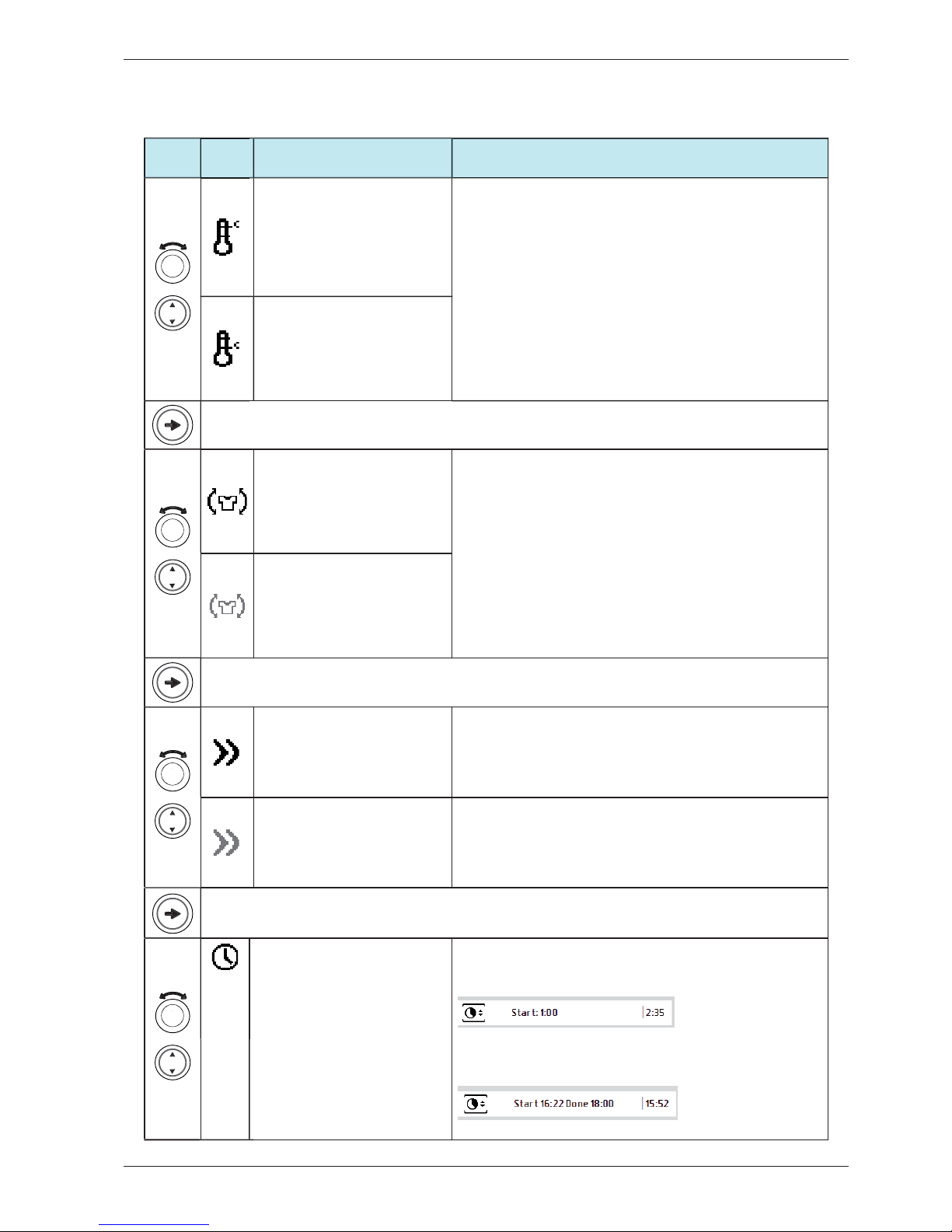
et the number of minutes incrementally. The selected time is
shown on the display. Try out different dryin
g
times.
6
A
ir Fluff, Air Fluff , Revitalise, Luftnin
g
spro
g
ram,
Koldlu
f
tprogram, Kald lu
f
t, Tuuletus,
V
entilation, Ventileren, Arie
gg
iamento, Aireado,
П
p
oвeт
p
ивaниe, Lüften
Use the Revitalise pro
g
ramme when you just want to refresh, air
or soften up items Set the number of minutes incrementall
y
. The
selected time is shown on the display. Try out di
ff
erent dryin
g
times
.
7
S
ettin
g
s,
S
ettin
g
s,
S
ettin
g
s, Inställnin
g
ar,
Indstillin
g
er, Instillin
g
er, Asetukset, Ré
g
la
g
e,
Instellingen, Impostazioni, Ajustes, Haстpoйки,
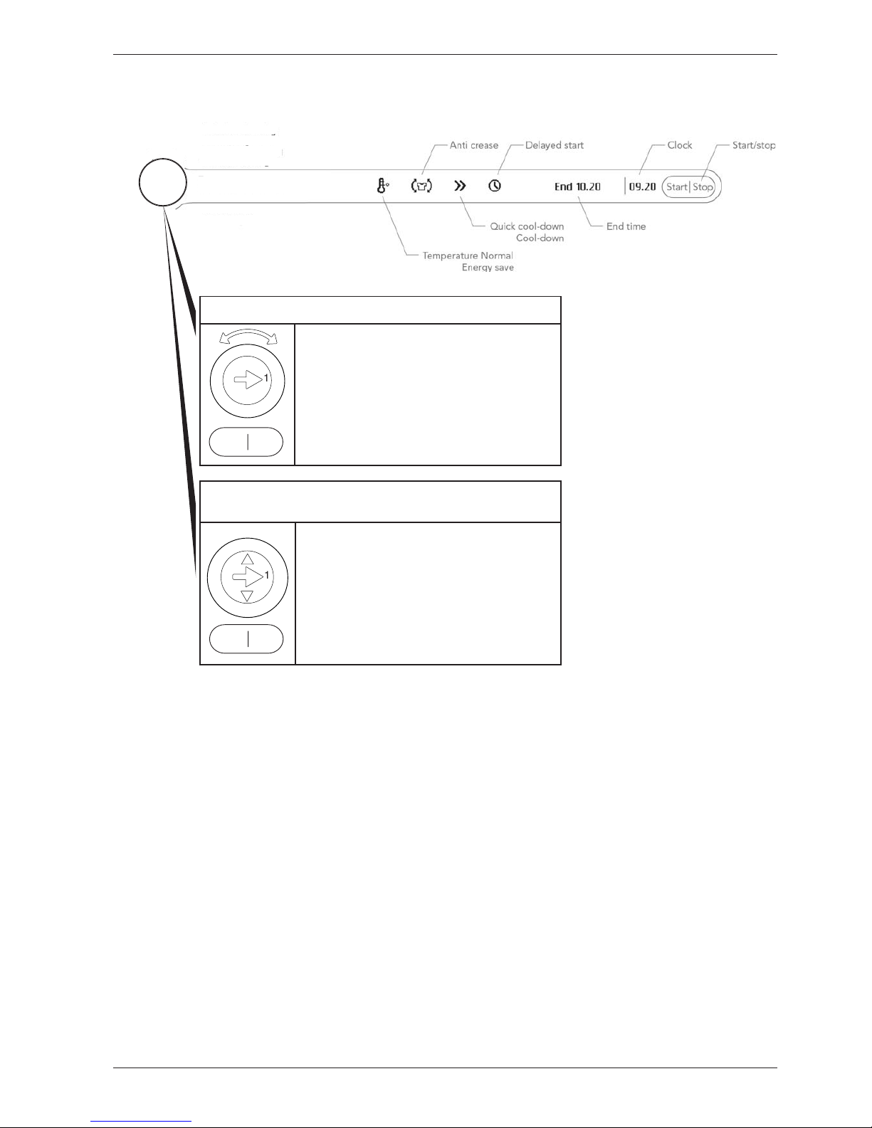
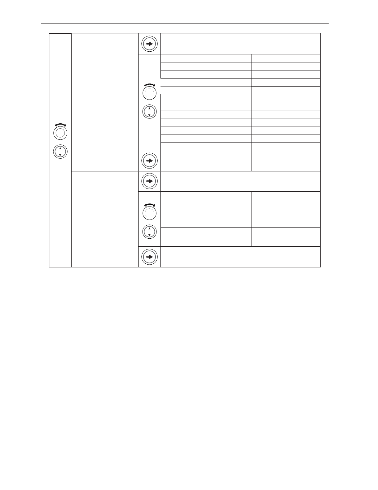
Ei
nste
ll
un
g
e
n
E
x
i
ts t
h
e pro
g
ramme menu an
d
a
d
vances to opt
i
ons or t
h
e menu
for Settin
g
s.
P
ress
/
t
ur
n
LC
D 1
C
omments/instruction
s
T
urn on t
h
e ma
i
n power supp
l
y
P
rogramme selection
The pro
g
rammes are displayed in the order they occur in L
C
D1. All display text lan
g
ua
g
e versions are displayed
.

S
ervice manual TD6
0
7
P
ress
/
tu
r
n
L
CD
2
LCD
3
Comments
/
instruction
s
Tem
p
erature Normal, Tem
p
erature
norma
l
,
T
emperatur norma
l
,
Tem
p
eratur normal, Tem
p
eratur
normal, Läm
p
ötila normaali, Tem
p
.
norma
l
,
N
orma
l
e temperatuur,
Tem
p
. normale, Tem
p
eratura
normal, Hopм.тeмпepaт
y
pa, Temp.
n
o
rm
al
Two possible choises o
f
temperature. Not avaliable
f
or programme at
p
ro
g
ramme 6 (”Air Fluff”
)
Temperature Low, Ener
g
y Save,
Temperatur låg, Temperatur lav,
Temperatur lav, Lämpötila matala,
Temp. faible, La
g
e temperatuur,
T
emp.
b
assa,
B
a
j
a temperatura,
H
изкaятeмпepaтypa, Temp.
niedri
g
Anti Wrinkle On
,
Anti crease On
,
S
kr
y
nkelfritt På , Anti-krøl Til ,
Antikrøll P
å
, Rypistymisen esto
P
äällä, Antifroissa
g
e On, Anti-kreuk
Aan, Antisgualcit. On, Antiarrugas
encen
did
o ,
П
poтив сминaния
B
кл.
,
Knitterschutz A
n
This is a useful feature if you cannot take the washin
g
out as soon as
the tumble dr
y
er has
f
inished.
The function prevents the clothes from remainin
g
in the same position
and becoming creased. The drum will rotate
f
or three seconds per
m
inute
f
or two hours once the dryin
g
pro
g
ramme has
f
inished
Not avaliable for programme at position 6
(
”Air Fluff”
)
Anti Wrinkle Off, Anti crease Off,
S
kr
y
nkelfritt Av, Anti-krøl Fra ,
Antikrøll Av , Rypistymisen esto
P
oissa, Antifroissa
g
e Off, Anti-kreu
k
Uit, Antisgualcit. Off, Antiarrugas
a
pa
g
ado, Пpoтив сминaния Bыкл.,
K
nitterschutz Au
s
Quick Cool-down, Quick cool-
down, Kort kylnin
g
, Hurti
g
kølin
g
,
H
urti
g
kjølin
g
, Lyhyt jäähdytys,
R
efroid.ra
p
ide, Snel afkoelen, Raffr.
rapido, En
f
ri. rapido, Быстpoe
o
xлaждeниe, Schnell abkühle
n
Th
e
l
oa
d
coo
l
s
i
n 3 m
i
nutes.
The option cannot be selected for the Air fluff pro
g
ramme
.
C
ool-down, Cool-down, Normal
k
y
l
n
i
n
g
,
N
orma
l
k
ø
li
n
g
,
N
orma
l
kjølin
g
, Normaali jäähdytys, Refroid
.
normal, Normaal afkoelen, Raffr.
normale, En
f
ri. normal, Hopм.
o
xлaждeниe, Normal abkühle
n
The machine cools the load in 1
5
minutes.
The option cannot be selected for the Air fluff pro
g
ramme
.
S
tart, Start, Start, Start, Start, Start,
S
tart, Démarrer,
S
tart, Avvio, Inicio,
С
тaрт, Start
(
Option for all pro
g
rams except
Timed dr
y)
Delayed start
(
when setting: ”No Real time”
)
The start o
f
the selected pro
g
ramme can be delayed
f
or up to 24 hours
(
in half an hour intervals). The delay and pro
g
ramme time is shown in
the displa
y.
Delayed start (when settin
g
: ”24 Hour
C
lock ” or ”12 Hour
C
lock”)
The start of the selected pro
g
ramme can be delayed for up to 24 hours
(
in half an hour intervals). Start and end times are shown in the displa
y.
Selecting Options
T
he options are displayed in the order they occur in L
C
D2 and L
C
D3. All display text lan
g
ua
g
e versions are

S
ervice manual TD6
0
8
S
tart - Done, Start-End, Start-Done,
S
tart-Klar,
S
tart-Færdi
g
,
S
tart
-
F
erdi
g
, Start-Valmis, Démarrer-Fin,
S
tart-Fertig, Avvio-Fine, Inicio-Fin,
С
тaрт-Кoнeц,
S
tart-
G
ereed
(
Option onl
y
for Timed dr
y)
Time program
(
when setting: ”No Real time”
)
D
esired pro
g
ramme time can be set.
S
elections up to 3 hours in units
of 15 minutes can be made. The selected pro
g
ramme time is shown in
the dis
p
la
y.
3
:
00
Time pro
g
ram (when settin
g
: ”24 Hour Clock ” or ”12 Hour Clock””
)
D
esired programme time can be set. Selections up to 3 hours in units
of 15 minutes can be made.
S
tart and end times are shown in the
display
.

S
ervice manual TD6
0
9
P
ress
/
t
urn
L
C
D 2 Press
/
t
ur
n
L
C
D
3
C
omments/instruc-
t
i
on
s
Settin
g
s, Settin
g
s, Settin
g
s,
I
nst
äll
n
i
ngar,
I
n
d
st
illi
nger,
I
nnst
illi
n
g
er,
A
setu
k
set,
R
ég
la
g
e, Einstellun
g
en,
I
mpostaz
i
on
i
,
Aj
ustes,
Haстрo
й
ки, Instellin
g
e
n
In the pro
g
ramme menu: Scroll
t
o programme 7 (Settings)
You will now enter the Settin
g
s menu.
1
Clock/Auto Start, 1 Clock,
1
Kl
oc
k
a
,
1
U
r
,
1
Kl
o
kk
e
,
1
Kello, 1 Horlo
g
e, 1 Klok, 1
O
rologio, 1 Reloj, Чaсы, 1 Uh
r
24hr Realtime
,
24 Hour Clock
,
24hr
Realtime, 24 timmarsvisning, 24 timers
ur, 24t rea
l
t
id
, 24
h
a
ik
a,
H
or
l
o
g
e 24
h
,
24 Std. Echtzeit, 24h Tempo reale, Relo
j
24 horas, Фo
р
мaтв
р
eмeни 24-ч., 24 uur
weerga
v
e
T
hree O’clock is displayed as
”
15.00”. Press S1 to access a
su
b
-menu w
h
ere you can set
t
he correct current time. Press
S1 again to store and exit the
su
b
-m
e
nu
.
12hr Realtime
,
12 Hour
C
lock
,
12hr
Realtime, 12 timmarsvisnin
g
, 12 timers
ur, 12t realtid, 12 h aika, Horloge 12 h,
12
S
td. Echtzeit, 12h Tempo reale, Relo
j
12 horas, Фo
р
мaтв
р
eмeни 12-ч., 12 uur
weerga
v
e
T
hree
O
’clock is displayed as
”03
.
00
”. Press
S
1 to access a
sub-menu where
y
ou can set
the
corr
e
ct curr
e
nt t
i
m
e
.
P
r
e
ss
S1 a
g
ain to store and exit the
sub-m
e
nu
.
N
o
R
ea
l
t
i
me,
N
o
R
ea
l
Ti
me,
N
o
R
ea
l
t
ime, Ej realtid, Intet ur, In
g
en realtid, Ei
aikaa, Pas d’horlo
g
e, Keine Echtzeit, No
t
em
p
o reale, Sin hora real, В
р
емя не
установлено,
G
een tijdsweer
g
ave
No Real Time. Press S1 to
r
eturn to pro
g
ramme menu.
Saves the settin
g
and returns to the pro
g
ramme menu
.
2 Buzzer Volume, 2 Audible
V
o
l
ume, 2
Lj
u
d
s
i
gna
l
, 2
Lydsi
g
nal, 2 Lydsi
g
nal, 2
Hälytysääni, 2 Volume buzzer,
2
V
o
l
ume e
i
n
d
s
i
gnaa
l
, 2
V
olume allarme
,
2 Volumen
t
imbre, Г
p
oмкoсть сигнaлa, 2
T
ons
i
gna
l
O
ff, Off, Off, Av, Fra, Av, Poissa, Off, Aus,
O
ff, apa
g
ado, Bыкл., Uit
No buzz
e
r
Low, Low, Low, Lå
g
, Lav, Lav, Matala,
Faible, Niedri
g
, Bassa, Bajo, Hизкaя,
Laag
Buzz
e
r that indicat
e
s th
e
e
nd o
f
a
pro
g
ramme or error
.
Normal, Normal, Normal, Normal, Normal,
N
orma
l,
N
ormaa
li,
N
orma
l,
N
orma
l,
Normale, Normal, Ho
р
мaльнaя, Normaal
Buzz
e
r that indicat
e
s th
e
e
nd o
f
a
programme
or
error.
High
,
High
,
High
,
Hög
,
H
ø
j
,
H
øy,
K
or
k
ea,
Elevé, Hoch, Alta, Alto, B??o?a?, Hoo
g
Buzz
e
r that indicat
e
s th
e
e
nd o
f
a
pro
g
ramme or error
.
Saves the setting and returns to the programme menu
.
M
ak
i
ng sett
i
ng
s
T
he settin
g
options below are shown in the order they occur in L
C
D2 (Position 7 under the pro
g
ramme menu is, however, shown in
LCD1). All display text lan
g
ua
g
e versions are displayed.

S
ervice manual TD6
0
1
0
3 Language, 3 Language,
3 Språk, 3 Spro
g
, 3 Språk,
3 Kieli, 3 Lan
g
ue, 3 Taal, 3
Lingua, 3 Idioma, Язык, 3
S
prach
e
US En
g
lish
AU En
g
lis
h
Default
s
v
e
nska
d
ans
k
no
r
sk
Suomi
F
r
a
n
cais
Nede
r
l
an
d
s
I
t
alia
n
o
Espano
l
Pyсски
й
Deutsch
4
C
hild-safe
,
4
C
hild-safe
,
4
Barnsäker, 4 Børnesikker, 4
B
arnes
ik
r
i
ng, 4
L
aps
il
u
kk
o, 4
S
écurité enfant, 4 Kindveili
g
e,
4 Avvio sicurezza, 4 Int. de
s
egur
id
a
d
, 4
Б
лoкиpoвкa oт
дeтe
й
, 4 Kindersicherun
g
On, On, On, På, Til, På, Päällä, On, An,
O
n, encendido, Bкл., Aan
If S1, S2, S3 or J1 are
p
ressed
or turned,
S
tart
S
2 +
S
1 must
b
e pressed to temporarily
de
activat
e
th
e
child-saf
e
start
(
is deactivated for 3 minutes
after).
Off
,
Off
,
Off
,
Av
,
Fra
,
Av
,
Poissa
,
Off
,
Aus
,
Off, apagado, Bыкл., Uit
Settin
g
deactivated.
S
aves the settin
g
and returns to the pro
g
ramme menu
.

S
ervice manual TD6
0
11
Programme selecto
r
1
2
2
1. Press the pro
g
ramme selector button to scroll between the various service menus.
2
. Turn the pro
g
ramme selector button to make a selection between the menus.
C
onfirm the selection and
g
o
to the next menu by pressin
g
the pro
g
ramme selector button (1)
.
3
. Press the
S
tart
/S
top button to confirm the settin
g
s and exit the service menu.
Service menu
This is how to enter the service men
u
+
I
f the machine is on: First turn off the power at the main power switch. Press and hold the Pro
g
ram
S
elector
while turnin
g
on the main power switch.
3x
P
ress the pro
g
ramme selector button 3 times within 5 seconds. You are now in the service menu.
S
ee
instructions below for navi
g
atin
g
the service menu
.
Programme selector button for integrated machine
s
1
2
2
1
. Press the pro
g
ramme selector button to scroll between the various options.
2. Press the small arrows to make a selection between the options.
C
onfirm the selection and
g
o to the next
o
ption by pressin
g
the pro
g
ramme selector button
(
1
).
3. Press the
S
tart
/S
top button to confirm the settin
g
s and exit the service menu
.
Start Stop
3
3
Start Stop

S
ervice manual TD6
0
12
P
ress
/
tu
r
n
LC
D 2 Comments/instruction
s
DataSerialNo, Data Ser Num,
DataSerialNo, DataSerialNo,
S
erienummer
,
S
erienummer
,
Dataversio Nro, N° de s
é
rie,
S
eriennummer, Num. di serie,
N° de serie, Сeри
й
ны
й
нoмeр,
S
erienummer
Date for pro
g
rammin
g
the software
(
Year_Week
)
C
U date code, CU Date Code,
C
U date code,
C
U datum kod,
C
U
dato kode, Styrekort prod dato,
C
U
p
vm koodi, Code date CU, CU
Datumscode,
C
odice data
C
U,
C
ódi
g
o fecha CU, Кoддaты БУ, CU
datacod
e
C
ontrol unit’s date of manufacture
(
Year_Week
)
S
oftware, Software, Software,
M
j
ukvara,
S
oftware,
S
oftware ver.,
Ohjelmisto, Lo
g
iciel, Software,
S
oftware, Software, Be
р
сия п
p
oг.,
S
oftwar
e
S
oftware version number.
No. of cycles, Number of
C
ycles,
No. of cycles, Antal cykler , Antal
cy
klusser, Antall bruk, S
y
klien lkm,
Nb. de cycles, Anzahl der Zyklen,
Numero cicli, N° de ciclos, Кoл-вo
циклoв,
A
anta
l
c
y
c
li
Number of cycles
/
pro
g
rammes run
Pres
s
to exit the service menu.
”Error_Number o
f
cycles
”
Last three errors and number of cycles (when the error occurred) shown. Total
reset deletes the error indications from the system. If the same error recurs at
di
ff
erent times, this is shown, but onl
y
once in the list
.
”Error_Number of cycles
”
”Error_Number o
f
cycles
”
Pres
s
to exit the service menu.
Testing, Test, Test, Tester, Test,
T
estaus,
E
ssa
i
,
T
est,
T
est,
T
est,
Teстиpoвaниe, Testen
Testin
g
Motor, Test motor,
Motortest, Tester motor, Test av
motor
,
M
oottor
i
test
i,
E
ssa
i
moteur
,
Test motor
,
Test motore
,
Test motor
,
Teст мoтo
p
a, Motor teste
n
Normal action: The motor will run continuously
.
Testin
g
Heater 1, Test heater 1,
Elementtest 1, Tester varmele
g
eme
1
,
Test av element 1
,
Vastustesti 1
,
Essai él. chauf 1
,
Test verw. element
1
,
Test el. risc. 1
,
Test elem cale
f
1
,
Teст T
Э
Ha 1, Heizun
g
stest 1
Motor runs continuously. Heater 1 runs re
g
ulated on and off by
C
U re
g
ardin
g
to
measured thermistor values. Total consum
p
tion is a
pp
. 9A in this mode. If value
di
ff
ers, do the
f
ollowing
:
1. Detach the panel
2
. Disconnect electrical connections at the
CU.
3
. Measure DC Ωfor heaters and related wires. For values and measure
p
oints,
see chapter ”
C
omponents and measurement values” and ”Wirin
g
dia
g
ram”
.
IF THE VALUES ARE INCORRECT:
C
heck the electrical function for connections and heater.
C
han
g
e parts if needed
.
IF THE VAL
U
E
S
ARE
CO
RRE
C
T:
a
)
Start the com
p
onent test
(
”Test heater 1”
)
b) Measure A
C
volta
g
e directly on the
C
U (see wirin
g
dia
g
ram for measurin
g
points
)
. Volta
g
e should be the same as power supply net
.
c
) If values are out of range: Replace the CU.
L
C
D shows ”
_
_
_
_
_
_
_
_
: XX°
C
YY°
C
ZZ °
C
”.
XX = tem
p
erature values for thermistor 1
Y
Y = tem
p
erature values
f
or thermistor 2
ZZ = temperature values
f
or thermistor 3
>100°C (XX) = short-circuit in thermistor 1 (heating element does not start)
10°C (XX) = thermistor 1 faulty (heating element heats but is only regulated by
the overheating protection).
>100°C (YY) = short-circuit in thermistor 2 (heating element does not start)
10°C? ± 2°C (YY) = thermistor 2 faulty (functions as vented dryer).
150°C (ZZ) = thermistor 3 short-circuited
25°C (ZZ) = thermistor 3 faulty
CO
NTIN
U
E
O
N NEXT PA
G
E
The options below are displayed in the order they occur in LCD 2. All display text language versions are displayed
.
S
ervice menu
Start Stop
Start Stop

S
ervice manual TD6
0
1
3
To veri
f
y indication on
f
aulty thermistor, do the
f
ollowin
g
:
1. Detach the
p
anel
2
. Disconnect electrical connections at the CU
.
3
. Measure D
C
Ω
for thermistor and related wires. For values and measure
points, see chapter ”Components and measurement values” and ”Wirin
g
di
agram
”.
I
F THE VAL
U
E
S
ARE IN
CO
RRE
C
T:
C
heck the electrical function for connections and thermistor. Change parts if
needed.
I
F THE VAL
U
E
S
ARE
CO
RRE
C
T:
a
)
Start the com
p
onent test
(
”Test heater X”
)
b) Measure A
C
volta
g
e directly on the
C
U (see wirin
g
dia
g
ram for measurin
g
points
)
. Volta
g
e should be 5VDc.
c
) If values are out of range: Replace the CU.
Thermistor 2 has no a
ff
ect in the component test
.
T
estin
g
Heater 2, Test heater 2,
Elementtest 2, Tester varmele
g
eme
2
,
Test av element 2
,
Vastustesti 2
,
Essai él. chauf 2
,
Test verw. element
2
,
Test el. risc. 2
,
Test elem calef 2
,
T
eст TЭHa 2, Heizun
g
stest 2
M
otor runs continuously. Heater 2 runs re
g
ulated on and off by CU re
g
ardin
g
to
measured thermistor values. Total consum
p
tion is a
pp
. 2A in this mode. If value
di
ff
ers,
f
ollow the instructions
f
or ”Testin
g
heater 1”
T
est
i
ng
D
ra
i
n,
T
est
d
ra
i
n,
T
ömnin
g
stest, Tester udpumpnin
g
,
T
est av tømmin
g
, Tyhjennystesti,
Essai essorage, Test a
f
voerpomp,
T
est scarico, Test drena
j
e, Teст
сливa, Abflusstes
t
D
rain
p
um
p
runs. I
f
no action:
1. Detach the panel
2
. Disconnect electrical connections at the
CU.
3
. Measure DC Ωfor drain
p
um
p
and related wires. For values and measure
points, see chapter ”
C
omponents and measurement values” and ”Wirin
g
dia
g
ram”
.
I
F THE VALUES ARE INCORRECT:
C
heck the electrical function for connections and drain pump.
C
han
g
e parts if
needed.
I
F THE VALUES ARE CORRECT:
a)
S
tart the component test (”Testin
g
drain”
)
b) Measure AC volta
g
e directly on the CU (see wirin
g
dia
g
ram for measurin
g
points). Voltage should be the same as power supply net
.
c
) If values are out of ran
g
e: Replace the
C
U.
d
)
If the values are correct: Check drain
p
um
p
for mechanical disturbance.
C
hange pump if necessary.
T
est
i
n
g
B
uzzer,
T
est
b
uzzer,
Si
g
naltest, Tester lydsi
g
nal, Test
av lydsignal, Äänimerkkitesti, Test
sig
na
l
sonore,
T
est e
i
n
d
s
ig
naa
l
,
T
est
allarme, Test timbre, Teст звyк
.
сигнaлa, Summertest
B
uzzer
i
s on cont
i
nuous
l
y.
Pr
e
ss to
e
xit th
e
s
e
rvic
e
m
e
nu.
0
Ad
j
ust L
C
D contrast (0 = default
)
+3
+2
+1
-
1
-
2
-
3
Pr
e
ss to
e
xit th
e
s
e
rvic
e
m
e
nu.
0
Adjustment o
f
drying time
D
ry level:
0
(
no extension, default level
)
, +5
(
5 minutes extension
)
, +10
(
10 minutes
extension), +15 (15 minutes extension), +20 (20 minutes extension).
+
5
+10
+15
+20
Press to exit the service menu.
Start Stop
Start Stop
Start Stop

S
ervice manual TD6
0
14
Startin
g
the production tes
t
1. Press the
S
to
p
button
(S
3
)
, then
p
ress the main
p
ower switch. Hold the two buttons until the L
C
D1-3 is
li
g
ht up. Then release. the buttons
2
. Press Start
(
S2
)
5 times.
The followin
g
is shown
:
• L
C
D 1: Production tes
t
• L
C
D 2:
S
oftware 1
• L
C
D
3
:
S
oftware
2
Testin
g
the motor and condensin
g
waterpum
p
3. Press the Start button
(
S2
)
.
•
Airin
g
dryer: AVLUFT is shown in L
C
D
3
•
C
ondenser dr
y
er: K
O
NDEN
S
E is shown in L
C
D
3
•
The motor and condensin
g
waterpump starts
(
for
a
i
r
i
n
g
d
ryer: on
l
y motor
i
s runn
i
n
g
t
h
oru
gh
out t
h
e se
-
q
uence)
.
•
Then
f
ill water in the water tank until the machine stops
(
check that the switch for condensation water works
).
4. Press the
S
top button (
S
3) to start the motor and pump
out the condensation water.
I
ndication of fault
s:
Fault indication
/
s
ymp
t
o
m
C
aus
e
Avluft
(
is shown even in
th
e
cas
e
o
f
cond
e
ns
e
d
ryer
)
S
hort or o
p
en circuit
i
n t
he
rm
i
stor 2 w
hi
c
h
a
lso includes bad
conn
e
ctions
e
tc.
Test
i
ng the heater, therm
i
stor and temperature regulat
i
o
n
5. Press the Programme selector button (S1)
.
•
He
at
e
r 1 starts
6
. Press the Pro
g
ramme selctor button (
S
1).
•
Heater 2 starts
•
L
C
D 1: Time
r
•
L
C
D 2: NT
C
1
•
LCD 3: NTC2
,
NTC
3
•
LCD 1-3 lights continuously and the machine runs
t
emperature re
g
ulation
f
or 15 minutes
.
•
LCD 1-3 starts flashin
g
, which means that temperature
r
e
g
ulation is finished.
•
Coolin
g
runs for 5 minutes.
•
The machine stops
.
Test
i
ng the
i
nterval t
i
me and buzzer tone
7
. Press the Pro
g
ramme selector button (S1)
.
•
The
motor starts an
d
runs at
i
nt
e
rva
l
s at t
he
sam
e
t
i
m
e
as a buzz
e
r sounds.
C
ancel the test programme.
8. Press the Pro
g
ramme selector button (S1).
• The
p
roduction test sto
p
s.
P
roduction te
st
T
he entire production test is run in a sequence as
f
ollows. You can cancel the test pro
g
ramme at any time
d
urin
g
the pro
g
ramme by openin
g
the door or pressin
g
the main power switch.

S
ervice manual TD6
0
1
5
F
ault indication
s
The below faults are indicated in plaintext in L
C
D 2. The table shows the indication in all lan
g
ua
g
es and
lan
g
ua
g
e variations.
LCD 2
C
aus
e
Ac
ti
on
O
verflow, Over Flow,
Ö
verfyllnad,
O
verfyldnin
g
, Overfyllin
g
,
Y
litulviminen, Tro
p
-
p
lein,
R
eservo
i
r
l
e
g
en,
T
ra
b
occamento,
Desbordamiento, Пe
р
eлив вoды,
Ü
berfüllt
A
micro switch, openin
g
,
f
or
d
etection of full, condensin
g
w
at
e
r contain
e
r. D
e
t
e
ction shall
s
tart 30 sec a
f
ter a pro
g
ram is
s
tarted. If the micro switch is
opened > 30 sec the program
cyc
l
e s
h
ou
ld
b
e stoppe
d
an
d
cleared.
C
heck if the customer has:
•
E
m
p
t
i
e
d
t
h
e tan
k
an
d
restarte
d
t
h
e mac
hi
ne
S
ervice action
:
•
Clean hoses and check voltage and resistance in the
d
ra
i
n pump
.
•
Check that the float has not
g
ot “stuck” and check the
f
unction of th
e
micro-switch.
Max Pro
g
ram Time, Max pro
g
ram
ti
me ,
M
ax
i
ma
l
programt
id
,
M
a
k
s
i
ma
l
p
ro
g
ramtid, Maks pro
g
ramtid, Max
ohjelma-aika, Dur
é
e maxi pro
g
., Tijd
oversc
h
re
d
en,
T
empo max. progr.,
Duración máx pro
g
, Пpeвышeниe
в
peмeни, Max. Pro
g
rammzeit
T
he cycle time exceeds 200
mi
nutes.
Th
e c
y
c
l
e
i
nterupts
and the pro
g
ramme is cleared
.
Hi
g
h
am
bi
ent temperature
combined with low element
output and low dryin
g
t
em
p
erature
l
ea
d
s to
condensation
f
ormation.
Poor cond
e
nsation du
e
to
bl
oc
ked
e
xt
e
rna
l
a
ir
C
heck if the customer has:
•
T
r
i
e
d
sp
i
nn
i
ng at a
hi
g
h
er spee
d
•
Has the machine switched o
ff
f
or 30 minutes be
f
ore
r
estartin
g
•
Good ventilation in the roo
m
S
ervice action
:
•
Ensure that the external air has free passage
.
Thermistor
f
ault
,
Thermistor
Fault
,
Thermistor fault
,
Termistor
f
el, Termostat
f
ejl,
Termistor
,
Termistorivika
,
Défaut
,
Termistorfehler
,
Termistore
,
Fallo
,
Te
р
мистo
р
, Tem
p
. sensor
f
out
1
) The circuit for the thermistor
i
s o
p
en
.
2) The thermistor is faulty
S
ervice action
:
C
heck the thermistors function. If needed, replace it
.
Clean condenser, Ren
g
ör
k
ondensor, Rens kon.sator, Rens
k
on.sator,
P
u
hdi
sta
l
au
hd
ut
i
n,
Nettoya
g
e condenseur, Reini
g
en
k
ondensor, Pulizia condensatore,
Limpiar condensador,
O
чистить
к
oндeнсaтoр, Kondenser reini
g
en
1
) Indicated for each 100 cycle.
2
)
Indicated if the machine has
i
ndicated ”
C
lean lint filter” 2
t
imes.
C
heck if the customer has:
•
C
leaned the condensor and filter
•
C
leaned other air ducts
Clean Lint Filter, Clean Lint Filter,
Ren
g
ör
f
iltret, Ren
g
ør
f
nu
gf
ilter, Rens
filter, Puhdista sihti, Nettoya
g
e filtre,
Reinig
f
ilter, Pulizia
f
iltro, Limpie
e
l filtro,
O
чистить фильтp,
S
ieb
r
eini
g
e
n
I
n
di
cat
ed
w
he
n a
i
r c
i
rcu
l
at
i
on
an
d
temperature are
i
ncorrect
Check if the customer has:
•
C
leaned the filter
After carrying out corrective actions as above, reset the fault indications by switching off the machine using
t
h
e ma
i
n
p
ower sw
i
tc
h.

S
ervice manual TD6
0
1
6
O
ther fault
s
Fault s
y
mpto
m
C
ause A
c
ti
on
Th
e
machin
e
will not start The outer door is not properl
y
closed. • Check that the door pin is activating the door
s
w
i
t
ch.
Th
e mac
hi
ne
i
s not supp
li
e
d
w
i
t
h
power
.
•
C
heck the fuses and connections.
Th
e mac
hi
ne stops
Th
e automat
i
c over
h
eat
i
n
g
protect
i
on
h
as tr
i
ppe
d.
C
heck if the customer has
:
• O
p
ened the door and cleaned the filter and
c
ond
e
ns
e
r uni
t
• Le
f
t the door open lon
g
enou
g
h
f
or the over
-
h
eatin
g
protection to be reset
and the display and LEDs to light u
p
•
A
ttempte
d
to restart t
h
e pro
g
ramme
S
ervice action
:
• Clean internal fan wheel, condenser, air ducts
and element
.
•
C
heck the seals.
The overheat
p
rotection in the motor has been
tr
i
ppe
d
.
•
C
lean and check the motor.
• I
f
necessary, replace the motor.
D
efe
ctiv
e
control uni
t
•
R
ep
l
ace contro
l
un
i
t.
Th
e was
hi
n
g
d
oes not
g
et dry
Air leaka
g
e at the door seals is a
ff
ectin
g
the
dryin
g
results
.
•
C
heck the sealin
g
strips.
Air leaka
g
e around the motor shaft affects the
d
ry
i
ng resu
l
t.
•
C
heck the seal around the motor shaft.
D
efe
ctiv
e
r
e
ar th
e
rmistor •
R
ep
l
ace t
h
e t
h
erm
i
stor
.
D
efe
ctiv
e
control uni
t
•
R
ep
l
ace contro
l
un
i
t.
The washin
g
does not
g
et dry.
Mixin
g
o
f
various types o
f
items can lead to
u
neven dryin
g
results
.
C
ustomer information
:
• Check that different types of items are not
mi
xe
d
i
n t
h
e same mac
hi
ne.
R
emove t
h
e
d
r
y
i
tems.
How full the machine is affects the dryin
g
results
.
C
ustomer information
:
•
C
heck that the machine is not overfilled. Re-
m
ove some o
f
the washin
g
i
f
necessary.
T
um
bl
e-
d
ry
i
n
g
ta
k
es too
l
on
g.
Th
e
lint
f
ilt
e
r is block
e
d
.
C
ustomer information
:
• Cleanin
g
the lint filter
.
The condenser unit is blocked
.
C
ustomer information
:
•
C
lean the condenser
.
The washing machine’s spinning a
ff
ects drying
.
C
ustomer information
:
•
S
pin at a minimum of 800 rpm.
The machine is in a room with poor ventilation
.
C
ustomer information
:
• Open doors to adjacent rooms.
The evacuation hose is too long, blocked or bent
.
C
ustomer information
:
•
T
ry to ma
k
e t
h
e
h
ose
l
en
g
t
h
as s
h
ort as pos
-
s
ible with as
g
entle bends as possible
.

S
ervice manual TD6
0
17
T
otal re
s
et
By pressin
g
S
T
O
P (
S
3) + MAIN P
O
WER
S
WIT
C
H when power on the machine shall total reset. All set-
tin
g
s is returned to default values).
H
eater 2 a
c
tivation
Heater 2 can be programmed active or inactive
.
Do the
f
ollowin
g
:
1. Press
S
T
O
P (
S
3) + MAIN P
O
WER
S
WIT
C
H
2
. Press STOP (S3) five times (within 10 sec.)
3
. Turn the Pro
g
ramme selector (J1), choose ”Heater 2 On” or ”Heater 2 Off”
.
Press the Programme selector (S1) to store the settings
.
Show room program mod
e
S
how room pro
g
ram mode shall be activated
/
deactivated by:
Pressin
g
START (S2) + MAIN POWER SWITCH

S
ervice manual TD
60
1
8
C
om
p
onents and measurement value
s
1
Item numbe
r
C
om
p
onen
t
Mea
s
urement valu
e
C
omment
s
80
618
24
M
otor 50
H
z,
2
20
/
240 V
Main winding: 23.8
Ω
Auxiliary winding: 28.1
Ω
C
urrent: 1.1 A; 270 W;
28
5
0
rp
m
80 618 9
5
M
otor 60 Hz
,
220/240 V
W
indin
g
resistance:
cable colour
g
rey-blue
25
.
5
Ω
cable colour
g
rey-red
1
6
.
0
Ω
C
urrent: 0.9 A
;
200 W
;
3300 r
pm
The motor is a 2-pin motor and is directl
y
conn
e
ct
e
d to th
e
fan for int
e
rnal air and
g
earin
g
for drivin
g
the cylinder. The
fan for
e
xt
e
rnal air is also driv
e
n on
condenser dr
y
ers.
7
3
829
92
C
apacitor 6 μ
F
The capacitor is mounted on the motor.
80
5
46
40
C
apacitor 4 μ
F
88
0
11
94
C
ondensin
g
waterpump
25W
111 Ω
80
7
62
02
E
M
C
filter with inductor Th
e
f
ilt
e
r
e
liminat
e
s int
e
r
fe
r
e
nc
e
to and
f
rom th
e
machin
e.
80
7
62
24
Thermistor
4
– 6 k
Ω
(at room
temperature 20 – 30°
C)
The thermistor controls temperature
regulation. I
f
the thermistor is short-
circuited or detaches
f
rom the control unit,
the programme is cancelled.
80
7
9
2
91
Th
e
rmistor 8 - 12 kΩ
(
at room
tem
p
erature 20 – 30°C
)
80
77
3
85
Thermostat/Overheatin
g
p
rotection
(
150°C automatic)
Th
e
th
e
rmostat
/overheatin
g
protection interrupts the
pro
g
ramme at too hi
g
h temperatures.
80
7
61
04
Doo
r
s
w
i
t
ch
The
f
ront door a
ff
ects a door switch
,
w
hi
c
h
i
nterrupts t
h
e pro
g
ramme w
h
en
the door is o
p
ened. I
f
the door has been
opene
d
an
d
c
l
ose
d
d
ur
i
n
g
t
h
e pro
g
ramme
t
h
e mac
hi
ne must
b
e restarte
d
us
i
n
g
t
h
e
start/sto
p
button
.
80
7
61
03
M
i
c
r
os
wit
c
h fl
oa
t If both contain
e
rs ar
e
ov
e
rfill
e
d th
e
pro
g
ramme is interrupted by a float switch
located on the lower holder. Overfillin
g
is
indicated in the display.
El
ectr
i
ca
l
connect
i
o
n
Th
e mac
hi
ne
i
s
d
e
li
vere
d
as s
i
ng
l
e p
h
ase
an
d
can
b
e sw
i
tc
h
e
d
b
etween 1950
W
, 10
A
an
d
2500
W
, 16
A
.
Adjustment between 1950 W
/
10 A
and 2500 W
/
16 A is carried out using
so
f
tware via buttons.
88
0
1
3
2
7
C
ontrol Unit com
p
l. TD60.
3
The control unit contains micro
p
rocessors
for controllin
g
pro
g
rammes, motor,
e
l
e
m
e
nt
e
tc.
80
7
92
87
H
eatin
g
Element 2500
W
Heater 1: 1950W, 24,5
Ω
Heater 2: 550W, 91,4
Ω
80
7
92
88
H
eat
i
ng
El
ement 3000
W
Heater 1: 1950W
,
24
,
5
Ω
Heater 2: 1050W
,
45
,
3
Ω
1
A
ll resistances shown in the table have tolerances of +
/
- 10%

S
ervice manual TD
60
1
9
T
e
c
hni
c
al dat
a
H
e
igh
t:
8
5
0
mm
W
i
d
th:
595
mm
De
p
th
:
5
8
5
mm
W
e
igh
t:
3
9k
g
(vented) 47 k
g
(condenser
)
Cylinder volume
:
111 l
Max. loading capacity: 6.0 k
g
RPM
:5
2
rp
m
Rated
p
ower: 19
5
0 W = 10
A
2
500 W = 16
A
Adjustment between 10 and 16 A is carried out usin
g
so
f
tware
v
ia buttons
.
Dryin
g
drum material:
S
tainless stee
l
O
uter casing material
:
P
ow
d
er-coate
d
an
d
h
ot-ga
l
van
i
ze
d
s
h
eet stee
l
or sta
i
n
l
ess stee
l
Set-up
:
S
tackin
g
or freestandin
g
Prot
e
ction class
:
IP X4

S
ervice manual TD
60
20
Wiring diagram
WIRES IN ALL MACHINES
WIRES IN SOME MACHINES
AP
F
NTC 2
BE
MO
NTC 1
MO
DB
FB
1950 W
550 /
1050 W
*A CONDENSE DRYER
*A
*A
*B IN SOME MACHINES
*B
CONNECTION BOX
FOR USA & CANADA
L
N
L
L1 2
L1 2
L2 2
L2 2
L
RECL
N
RECL
RECG
INKB
AP
INKB
FORMAT A3
This document must not be copied without
our written pemission, and the contents
thereof must not be imparted to a third party
nor be used for any unauthorized purpose.
Contravention will be prosecuted.
Asko Cylinda AB
CIRCUIT DIAGRAM TD60.3
80 788 72 - 00
*A NTC 3
T1
T2
TB
N
L
3
4
56
*B
T3
*B
RESISTANCES AT ROOM TEMPERATURE (CA. 20°C/68°F)
VALUES WITH +/-10% ARE REGARDED AS NORMAL
COMPONENT
F: RADIO INTERFERENCE SUPPRESSION FILTER 680K Ohm
NTC 1: THERMISTOR 1 4 - 6 K Ohm
NTC 2: THERMISTOR 2: 4 - 6 K Ohm
NTC 3: THERMISTOR 3: 12 - 8 K Ohm
AP: DRAIN PUMP: 111 Ohm
EL: HEATING ELEMENT 550W 91.4 Ohm
EL: HEATING ELEMENT 1050W 45.3 Ohm
EL: HEATING ELEMENT 1950W: 20.5 Ohm
T1: THERMOSTAT, OVERHEATING (HEATER)
T2: THERMOSTAT, FAN HOUSING
T3: THERMOSTAT, OVERHEATING (HEATER)
FB: FLOAT SWITCH
DB: DOOR SWITCH
MO: MOTOR PUMP
TB: MAIN SWITCH
Other manuals for TD60
2
Table of contents
Other Asko Dryer manuals