Asoka Pluglink PL9950-BBR User manual

User’s Guide
PlugLink 9950 Cable/DSL Router
PL9950-BBR
PL9950UG-060106

Asoka® User’s Guide
PlugLink 9950 Cable/ DSL Router PL9950-BBR
Page 2 of 43
© 2006 Asoka USA Corporation. All rights reserved.
Trademarks
Asoka, PlugLi nk and the Asoka l ogo are registered trademarks or trademarks of Asoka USA
Corporation.
Other brand and product names are registered trademarks or trademarks of their respecti ve
holders.
Statement of Conditions
In the interest of improving internal design, operational function, and/ or reliability, Asoka
reserves the right to make changes to the products described in this document without notice.
Asoka does not assume any liability that may occur due to the use or application of the
product(s) or circuit layout(s) described herein.

Asoka® User’s Guide
PlugLink 9950 Cable/ DSL Router PL9950-BBR
Page 3 of 43
Table of Contents
Chapter Title Page
1 Introdu ction 4
2 Important Safety Information 5
3 Learning A bo ut your Powerli ne Ro uter 6
4 Preparing to Install 10
5 Installing the Powerline Router 11
6 Logging o n 12
7 Web-based User Interface 13
8 Connectin g to your I SP 15
9 Changing LA N Settings 18
10 Configuring the Firewall 21
11 Router Admini stration 31
Appendixes 37

Asoka® User’s Guide
PlugLink 9950 Cable/ DSL Router PL9950-BBR
Page 4 of 43
Chapter 1
Introduction
Thank you for purchasing a PlugLink 9950 Cable/ DSL Router (PL9950-BBR) from Asoka. This router
lets you net work your home or office by simply pluggi ng directly in to your wal l outl et. Now,
networking i s as easy as pl ugging in a ni ght li ght. With your PlugLink 995 0 Cable/ DSL Router, you
can easily share your high- speed Internet broadband, mp3s, video and gaming t hroughout the
home or office without pulling any new cabling.
This unit will not interfere with other household appliances such as hair dryers, vacuum cleaners
or microwave ovens. Consuming only 5 watts of power, it is environmentally friendly and will not
noticeably increase your electrical bill. It is a simple, secure and reliable choice for web surfing,
playing games, for compl imenti ng your existi ng wireless network, mp3 streami ng, and ev en high-
defini tion (HD) v ideo sharing.
This User’ s Guide shows you how to connect your P lugLink 99 50 Cable/ DSL Rout er to your PC.
Setup is easy. Just follow the instructions in this guide and your network will be up and running in
a matter of minutes.

Asoka® User’s Guide
PlugLink 9950 Cable/ DSL Router PL9950-BBR
Page 5 of 43
Chapter 2
Important Safety Instruction for the PlugLink 9950 Cable/ DSL Router
The following precaut ions should be taken when usi ng this product:
Read all instructions before installing and operating this product.
Do not open the cover on thi s product and/or alter thi s product in any way.
Follow common household electrical safety practices.
If you have any ques tions or concerns regarding these safety measures, please contact
Monday through Friday from
9:00 am t o 5:00 pm PST (excluding holidays.)

Asoka® User’s Guide
PlugLink 9950 Cable/ DSL Router PL9950-BBR
Page 6 of 43
Chapter 3
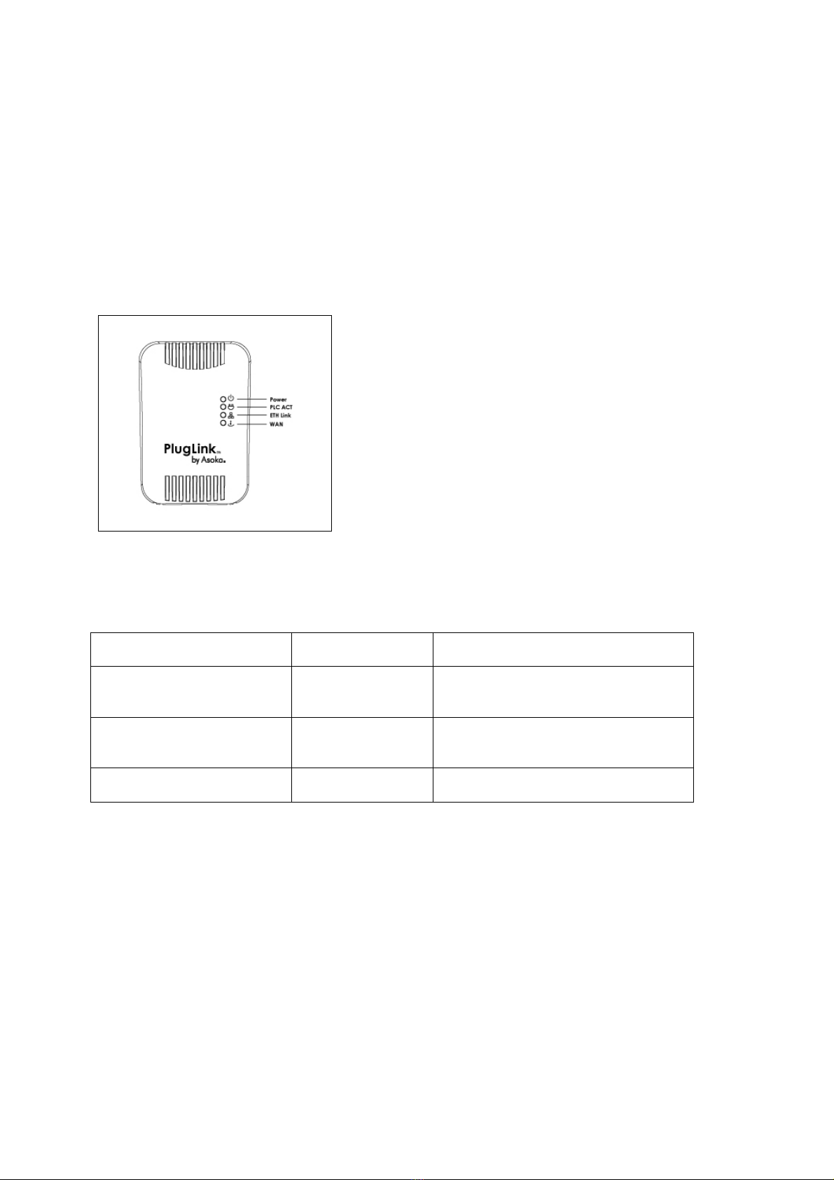
Learning about your PlugLink 9950 Cable/ DSL Router
Package Contents
PlugLink 9950 C able/ DSL Router (PL9950-BBR)
6 ft. Et hernet cabl e
Quick Installation Guide
Install ation Resource CD
Warranty and Support Information Card
If any of th e parts are i ncorrect, missing or damaged contact the retailer where you made your
purchase. Keep the carton, including the original packing materials, in case you need to return
the unit for repair.
System Requirements
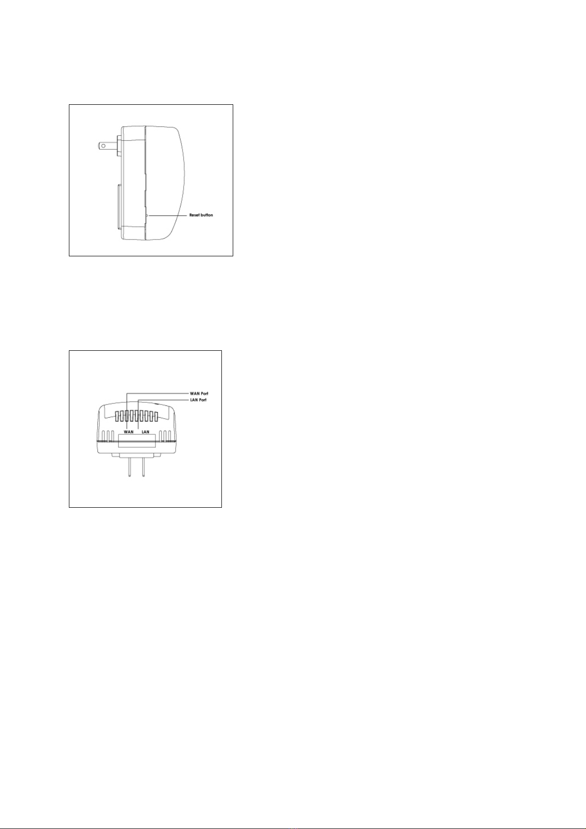
Cabling and Comput er Hardware
To use the PL9950- BBR router on your network, each computer must h ave an in stall ed
Ethernet Network Interface Card (NIC) and an Ethernet Cabl e. If th e computer is connected
to your network using an Ethernet NIC at 100 Mbps, you must use a Category 5 (Cat 5) cable
such as the one provided with your router. The cable or DSL broadband modem must
provide a standard 10 Mbps (10BASE-T) or 100 Mbps (100BASE-Tx) Ethernet interface. The
computer must be running ei ther Windows (98SE or higher) or Mac OS (X.1 or hi gher) an d
have at least 200 Mhz or fast er processing speed and a 64Mbs of RAM.
Computer Network Configuration Requirements
The PL9950-BBR router i ncludes a buil t-i n Web Configuration Manager. To access the
configurati on menus on the PL9950-BBR router, you must use a web browser (such as
Microsoft internet Explorer or Mozilla Firefox) that has Macromedia Flash and a Java-enabled
program that supports HTTP uploads. It i s recommended that you use Internet Expl orer 6.0 or
Mozilla Firefox 1.5 or above.
For the initial setup of your router, you will need to connect a computer to the router. This
computer has to be set to automatically get its TCP/IP configuration from the router via
DHCP. For i nformation on how to configure your computer, please see Appendix A.
Broadband Access and Configurati on Requirements
Depending on how your Internet servi ce set up your account , you may need one or more of
these configuration parameters to connect your router to the Internet:
o Host and Domain Names
o ISP Login Name and Pass word

Asoka® User’s Guide
PlugLink 9950 Cable/ DSL Router PL9950-BBR
Page 7 of 43
o ISP Domain Name Server (DNS) Addres s
o Fixed IP Address which is also known as Stati c IP Address
For your convenience, see
Appendix A for an easy-to-use form as a guide t o ask t he
appropriate information from your Internet service provider.
The Front Panel
The front panel of the PL9950-BBR Router contains the status lights described below.
Figure 3-1: PL9950-BBR Front Panel
You can use the status lights to v erify connections. Viewed from top to bottom, left to right, the
table descri bes the light s on the front panel of the uni t.
Table 3-1: Status Light Descriptions
POWER On
Off
Indicates Devi ce Powered On
Indicates No Power
PLC ACT
Blinking
Off
Indicates Activity on Powerline
Indicates No Activ ity on Powerli ne
(Should blink Intermittently)
ETH Li nk On
Blinking
Off
Indicates Ethernet C onnectiv ity
Indicates Ethernet Traffic
Indicates No Ethernet Activity
WAN On
Off
Indicates Activity on t he WAN
Indicates No Activity on the WAN
Left Panel
The left panel of the PL9950-BBR Router contai ns a reset button as shown i n figure 3-2.

Asoka® User’s Guide
PlugLink 9950 Cable/ DSL Router PL9950-BBR
Page 8 of 43
Figure 3-2: PL9950-BBR Left Panel
The Bottom Panel
The bottom panel of the PL9950-BBR Router contains a WAN port and a LAN port as shown i n
figure 3-3.
Figure 3-3: PL9950-BBR Bottom Panel
The Rear Panel
The label on the rear panel of the PL9950-BBR Router contains the items listed below.
Model Number
Unique device password
PLC MAC address
Ethernet MAC address
Serial number
Note: For future convenience, please write this information down in your Warranty Support
Information card.

Asoka® User’s Guide
PlugLink 9950 Cable/ DSL Router PL9950-BBR
Page 9 of 43
Figure 3-4: Rear Label

Asoka® User’s Guide
PlugLink 9950 Cable/ DSL Router PL9950-BBR
Page 10 of 43
Chapter 4
Preparing to Install the PlugLink 9950 Cable/ DSL Router
The PlugLin k 9950 Cable/ DSL Rout er lets you set up a home or an office net work using your
existi ng electri cal outlet s. It can also easily compli ment your existi ng network by connecting t o
any 10BaseT/ 100BaseT Ethernet-capable devi ce.
In order to share a Broadband connection between computers, all you will need is:
One (1) PL9650-ETH dev ice attached t o each computer or one (1) PL9550-WAP device for
any wireless-enabl ed computers
Standard Cable/DSL Modem
One (1) PL9950-BBR devi ce
Figure 4-1: Shared broadband connection network diagram.

Asoka® User’s Guide
PlugLink 9950 Cable/ DSL Router PL9950-BBR
Page 11 of 43
Chapter 5
Installing the PlugLink 9950 Cable/ DSL Router
Note: Do not connect the PlugLi nk 9950 Cable/ DSL Router to a power st rip, extension cord,
unint erruptibl e power supply (UPS), or surge protector. This may prevent the unit from worki ng
properly or degrade the network performance.
Note: Shut down any programs that are running on your computer prior to installing the PL9950-
BBR Router.
1. Connect the modem vi a an Ethernet cabl e supplied by your modem manufacturer into the
port labeled WAN on the bottom of t he 9950 Cable/ DSL Router.
2. Connect your computer in to the LAN port on the bot tom of the 9950 C able/ DSL Router
using the suppl ied Ethernet cabl e.
3. Plug the PL9950-BBR directly into an available power outlet.
4. Plug in your modem and rest art your computer.
Figure 5-1: Diagram of the hardware setup.
5. Check the LEDs on the front panel of the PL9950-BBR Router. All four LEDs should be either lit
or blinking intermittently.

Asoka® User’s Guide
PlugLink 9950 Cable/ DSL Router PL9950-BBR
Page 12 of 43
Chapter 6
Logging On
1. Open a web browsing application (Internet Explorer or Mozilla Firefox).
2. In the address or navigat ion fiel d, t ype
192.168.1.1 and press Enter.
Figure 6-1: Login Address
3. For security, the PL9950-BBR Rout er has its own user ID and password. When prompted, enter
admin
for t he router user ID ,
welcome
for the router password, bot h in lower case lett ers, and
press Login. To change t he user ID and password, see “Changing the Administ rator Logi n
Information” on page 31.
Note: The rout er user name and passw ord cannot be the same as any user name or password
you use to log in to your Internet connection.
Figure 6-2: Login Screen

Asoka® User’s Guide
PlugLink 9950 Cable/ DSL Router PL9950-BBR
Page 13 of 43
Chapter 7
Understanding the Web-Based User Interface
When you access the web-based user interface, the System Details page is the first page you will
see. The Syst em Detai ls page shows you a quick view of the PL99 50-BBR Router’ s status and
settings. All setup pages can be accessed from this page.
Figure 7-1: System Details page (a.k.a. Home page)
1. Quick Main Navigation Links
The User Interface (UI) is divided into four main logical sections, and you can go directly to
any of the four sections by clicking directly on each of these links.
2. Quick Sub Navigations links
When you enter into each of the four main logical sections, a sub navigation link that
corresponds to the main logical section will appear.
3. Home Button
The Home button is av ailabl e on every page of the UI. Pressing this but ton wil l take you back
to the home page, which is the system details page.
4. Glossary Button
The Glossary button i s avail able on every page of the UI. Pressing th is butt on will take you to
a glossary page that defines many of the technical terms used in this UI.
5. Help Button
The Help button is available on every page of the UI. Pressing this button will take you to a
help page that provides detailed explanations and steps for configuring your PL9950-BBR
Router.
6. Logout Button
The Logout button is available on every page of the UI. Pressing this button will enable you to
log out of the PL9950- BBR Router wit h the cli ck of a button.

Asoka® User’s Guide
PlugLink 9950 Cable/ DSL Router PL9950-BBR
Page 14 of 43
7. Detailed Information
Shows you detai led informat ion about t he PL9950-B BR Router that i ncludes: model number,
firmware v ersion number, hardware version, serial number, In ternet Wide Are a Netw ork (WAN)
settings, Local Area Network (LAN) settings and firewall settings.
8. Page Name
The page you are on i s identi fied by thi s name.

Asoka® User’s Guide
PlugLink 9950 Cable/ DSL Router PL9950-BBR
Page 15 of 43
Chapter 8
Connecting to your Internet Service Provider (ISP)
The WAN tab is where you will set up your PL9950-BBR Router to connect to your Internet Service
Provider (ISP). The PL9950-B BR Router is capable of connect ing to vi rtually any ISP’s syst em,
provided you have correctl y configured the PL9950-BBR Rout er’s setti ngs for your ISP’s
connection t ype. Y our ISP connection sett ings are provided t o you by your ISP. To configure the
PL9950-BBR wit h the sett ings that your ISP gave you, foll ow these st eps:
1. Under Connection Type, click on the connection type you use.
2. Click Apply.
Figure 8-1: Selecting your connection type.
Choosing Internet Connection Type
1. Selecting your Internet Service Provider (ISP) Connection Type to Dynamic IP: A dynamic
connection type is the most common connection type found with cable modems. Setting
the connection type to Dynamic i n many cases is enough to complete the connecti on to
your ISP.
Figure 8-2: Dynamic IP Screen

Asoka® User’s Guide
PlugLink 9950 Cable/ DSL Router PL9950-BBR
Page 16 of 43
2. Selecting your Internet Service Provider (ISP) Connection Type to Static IP:
A st atic IP address
connection t ype is less common than ot her connection types. If your ISP uses stati c IP
addressing, you will need your IP address, subnet mask, and ISP gateway address. This
information is available from your ISP or on the paperwork that your ISP left with you. Type in
your information. Click Apply.
Figure 8-3: Static IP Screen
3. Selecting your Internet Service Provider (ISP) Connection Type to PPPoE: Most DSL providers
use PPPoE as the connection t ype. If you use a DSL modem to connect to the Internet, your
ISP may use PPPoE t o log you into the servi ce. If you have an Internet connect ion that
doesn’t require a modem, you may al so use PPPoE. Type in your informati on and click Apply.
Figure 8-4: PPPoE IP Screen
Setting Domain Name Server (DNS) Information
After you have selected and configured your connection type, you will need to set the DNS
Server information.
1. Under the WAN sub menu, click on DNS.
2. Enter the DNS information provided to you by your ISP and click Apply.

Asoka® User’s Guide
PlugLink 9950 Cable/ DSL Router PL9950-BBR
Page 17 of 43
Figure 8-5: DNS Screen
Congratulati ons! Happy surfing!

Asoka® User’s Guide
PlugLink 9950 Cable/ DSL Router PL9950-BBR
Page 18 of 43
Chapter 9
Changing LAN Settings
All set tings for th e internal LAN set up of the PL9950-BBR Rou ter can be viewed and changed
here. C hanging LAN Settings i s recommended for adv anced users only.
Figure 9-1: LAN Setting Page
1. IP Address
The IP address is the i nternal IP address of the PL99 50-BBR Router. The default IP address is
192.168.1.1.To change the setti ngs of the PL9950-B BR, type t his IP address int o the address
bar of your browser. This address can be ch anged if needed and is optional and i s
recommended only for advanced users. To change t he IP address, t ype in the new IP
address and click Apply.
2. Subnet Mask
There is no need to chan ge the subnet mask. This is a unique advanced feature of your
PL9950-BBR Router. It is possi ble to change the subnet mask if necessary; however, do not
make changes to the subnet mask unless you have a specific reason to do so. The default
setting is 255.255.255.0.
3. DHCP Server
The DHCP server functi on simpli fies sett ing up a network by assigning IP addresses t o each
computer on the netw ork automatical ly. The default set ting i s ON. The DHCP server can be
turned OFF if necessary; however, in order to do so you must manually set a static IP address
for each comput er on your net work. To turn the DHCP server OFF, uncheck the box next to
the word Enable.
4. DHCP Scope
DHCP Scope is the range of IP addresses set aside for dynamic assignment to the comput ers
on your network, defined by a Start ing Address and an Endi ng Address. The default range is
between the numbers 2 and 254 (253 comput ers). If you want t o change this number, you
can do so by enteri ng a new starting and/or ending IP address here.
5. Lease Time
The duration of time that the DHCP server will reserve an IP address for each computer.

Asoka® User’s Guide
PlugLink 9950 Cable/ DSL Router PL9950-BBR
Page 19 of 43
6. Local Domain Name
The default setting for Local Domain Name is Asoka. You can set a local domain name
(network name) for your network. There is no need t o change thi s setti ng unless you have a
specific advan ced need to do so. You can name the network anyth ing you want.
Configuring the Powerline Network Settings
The Powerline link in the LAN Sub menu lets you make changes to the Powerline network settings.
From this tab you can make changes to the Powerline network name and encryption security
setti ngs.
To view and configure the Powerline network settings, you must first log in. The default Powerline
network sett ings password is PlugLink. To change the default Powerline network settings
password, see Chapter 11 of this User’s Manual.
Figure 9-2: Powerline Network Network Settings Login Screen
After logging in to the Powerline network settings page, you will be able to view all the Powerline
devices connected to your network and to set the local Powerline device password for the 9950
Cable/ DSL Router.
Figure 9-3: Powerline network settings page
1. Local Powerline Device Password
The Local Powerline Device Password is the password for the PL9950-BBR. This password allows
other Powerline devices to communicate with each other. By default, the local Powerline
device password i s PlugLink. To change the default local Powerline device password, simply
type in a new password in the field and click Apply.

Asoka® User’s Guide
PlugLink 9950 Cable/ DSL Router PL9950-BBR
Page 20 of 43
2. Powerline Device List
The Powerline device list provides a list of Powerline devices connected to your Powerline
network. The Powerline device list only displays the other Powerline devices on the network that
have the same local Powerline device password.
This manual suits for next models
1
Table of contents
Other Asoka Network Router manuals