manuals.online logo
Brands
  1. Home
  2. •
  3. Brands
  4. •
  5. ASROCK
  6. •
  7. Motherboard
  8. •
  9. ASROCK A320TM-ITX User manual

ASROCK A320TM-ITX User manual

Other manuals for A320TM-ITX

1

Other ASROCK Motherboard manuals

ASROCK 760GM-HDV User manual

ASROCK

ASROCK 760GM-HDV User manual

ASROCK E3C226D2I User manual

ASROCK

ASROCK E3C226D2I User manual

ASROCK H61M - ANNEXE 392 User manual

ASROCK

ASROCK H61M - ANNEXE 392 User manual

ASROCK B760M PRO RS User manual

ASROCK

ASROCK B760M PRO RS User manual

ASROCK Z590 Phantom Gaming-ITX/TB4 User manual

ASROCK

ASROCK Z590 Phantom Gaming-ITX/TB4 User manual

ASROCK 760GM-S3 User manual

ASROCK

ASROCK 760GM-S3 User manual

ASROCK P4I45PE R3.0 User manual

ASROCK

ASROCK P4I45PE R3.0 User manual

ASROCK EP2C612D16T-4L User manual

ASROCK

ASROCK EP2C612D16T-4L User manual

ASROCK 4Core1600P35-WiFi User manual

ASROCK

ASROCK 4Core1600P35-WiFi User manual

ASROCK H61 Pro BTC User manual

ASROCK

ASROCK H61 Pro BTC User manual

ASROCK W480D2I User manual

ASROCK

ASROCK W480D2I User manual

ASROCK H510M-HVS R2.0 User manual

ASROCK

ASROCK H510M-HVS R2.0 User manual

ASROCK M3A770DE - V1.0 User manual

ASROCK

ASROCK M3A770DE - V1.0 User manual

ASROCK Fatal1ty H97 Performance Series User manual

ASROCK

ASROCK Fatal1ty H97 Performance Series User manual

ASROCK P55DE PRO - User manual

ASROCK

ASROCK P55DE PRO - User manual

ASROCK X570 PRO4 User manual

ASROCK

ASROCK X570 PRO4 User manual

ASROCK EPC621D6U User manual

ASROCK

ASROCK EPC621D6U User manual

ASROCK Z170 Extreme6+ User manual

ASROCK

ASROCK Z170 Extreme6+ User manual

ASROCK Z270M User manual

ASROCK

ASROCK Z270M User manual

ASROCK ALIVENF6G-DVI User manual

ASROCK

ASROCK ALIVENF6G-DVI User manual

ASROCK SuperAlloy Z170 Pro4S User manual

ASROCK

ASROCK SuperAlloy Z170 Pro4S User manual

ASROCK H55M/USB3 User manual

ASROCK

ASROCK H55M/USB3 User manual

ASROCK ALIVENF5-ESATA2 -2943 - User manual

ASROCK

ASROCK ALIVENF5-ESATA2 -2943 - User manual

ASROCK H370M-HDV User manual

ASROCK

ASROCK H370M-HDV User manual

Popular Motherboard manuals by other brands

Gigabyte MNJ190I-FH user manual

Gigabyte

Gigabyte MNJ190I-FH user manual

Biostar HI-FI-Z87X-3D Setup manual

Biostar

Biostar HI-FI-Z87X-3D Setup manual

Atmel SAM9753PIA-DK user guide

Atmel

Atmel SAM9753PIA-DK user guide

Coapt GEN2 Handbook

Coapt

Coapt GEN2 Handbook

Supero SUPER P4DL6 user manual

Supero

Supero SUPER P4DL6 user manual

Cypress CY3210-PSoCEVAL1 quick start guide

Cypress

Cypress CY3210-PSoCEVAL1 quick start guide

Fujitsu D2831 Short description

Fujitsu

Fujitsu D2831 Short description

Industrial Computers ADE-6050 user manual

Industrial Computers

Industrial Computers ADE-6050 user manual

Asus TUF Z270 MARK 2 manual

Asus

Asus TUF Z270 MARK 2 manual

DFI NB71-BC user manual

DFI

DFI NB71-BC user manual

Norco POS-7893 user manual

Norco

Norco POS-7893 user manual

Intel DG965MS specification

Intel

Intel DG965MS specification

Asus B85M-VIEW PAKER user manual

Asus

Asus B85M-VIEW PAKER user manual

Asus P5G41T-M LX V2 user manual

Asus

Asus P5G41T-M LX V2 user manual

Gigabyte GA-K8VT800-RH user manual

Gigabyte

Gigabyte GA-K8VT800-RH user manual

Gigabyte Z790M AORUS ELITE user manual

Gigabyte

Gigabyte Z790M AORUS ELITE user manual

Semtech SC120 user guide

Semtech

Semtech SC120 user guide

Meridian Innovation MI0801 user manual

Meridian Innovation

Meridian Innovation MI0801 user manual

manuals.online logo
manuals.online logoBrands
  • About & Mission
  • Contact us
  • Privacy Policy
  • Terms and Conditions

Copyright 2025 Manuals.Online. All Rights Reserved.

A320TM-ITX Quick Installation Guide
12
Audio
CODEC
1
USB_4_5
HDLED RESET
PLED PWRBTN
PANEL1
1
COM1
14
DC Jack
HDMI1
HDMI2
Super
I/O
BIOS
ROM
M.2 WiFi
M.2 SSD
CPU_FAN2
CPU_FAN1
8
SOCKETAM4
A320TM-ITX
RoHS
16 15
10
DDR4_A2
DDR4_A1
SATA_1
1
SATAPWR1
Plug DDR4_A2 First
2
Ultra M.2
PCIe Gen3 x4
CLRCMOS1
1
PANEL_
DISABLE1
1
4
1
USB_6_7
5 6
LVDS1
BKT_PWR1
1
1
BLT_VOL1 VCC_PWR_SEL
1
7
11
13
31
11
SPK_OUT1
1
USB 3.1 Gen1
T: USB2
B: USB3
USB 3.1 Gen1
T: USB0
B: USB1
RJ-45
Headphone
Mic In
ATX_PWR1
1
HD_AUDIO1
17
9
P/N: 15G067029000AK V1.0
*15G067029000AK*
2 3
Package Contents
Motherboard Layout Motherboard Layout
4SO-DIMM
Take note of the following precautions before you install motherboard components or change any
motherboard settings.
1. Unplug the power cord from the wall socket before touching any components.
2. To avoid damaging the motherboard’s components due to static electricity, NEVER place your
motherboard directly on the carpet or the like. Also remember to use a grounded wrist strap or
touch a safety grounded object before you handle the components.
3. Hold components by the edges and do not touch the ICs.
4. Whenever you uninstall any component, place it on a grounded anti-static pad or in the bag
that comes with the component.
5. When placing screws into the screw holes to secure the motherboard to the chassis, please do
not over-tighten the screws! Doing so may damage the motherboard.
1
• A320TM-ITX Motherboard (in Mini-ITX Form Factor)
• A320TM-ITX Quick Installation Guide (Optional)
• 1 x in-Mini ITX I/O Shield (Optional)
• 1 x Mini ITX I/O Shield (Optional)
• 1 x Serial ATA (SATA) Data Cable (Optional)
• 1 x SATA Power Cable (Optional)
• 2 x Screws for M.2 Sockets (M2*2) (Optional)
14 pin 19V Power Connector (ATX_PWR1)
2SATA3 Connector (SATA_1)
3SATA Power Connector (SATAPWR1)
4Clear CMOS Jumper (CLRCMOS1)
5USB 3.0 Header (USB3_4_5)
6USB 3.0 Header (USB3_6_7)
7Backlight Power Jumper (BKT_PWR1)
8Backlight Control Header (BLT_VOL1)
9
Panel (LVDS) Disable Jumper (PANEL_DISABLE1)
10 Panel Power Jumper (VCC_PWR_SEL)
11 LVDS Connector (LVDS1)
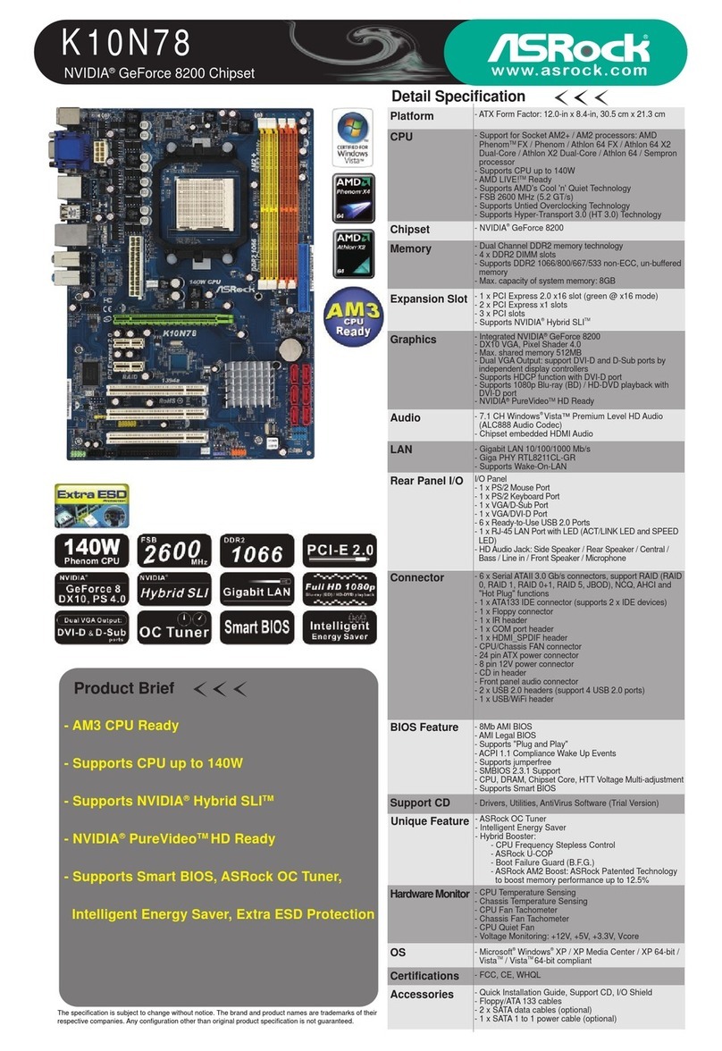
12 2 x 260-pin DDR4 SO-DIMM Slots
(DDR4_A1, DDR4_A2)
13 CPU Fan Connector (CPU_FAN1)
14 CPU Fan Connector (CPU_FAN2)
15 System Panel Header (PANEL1)
16 Internal Speaker Header (SPK_OUT1)
17 Front Panel Audio Header (HD_AUDIO1)
I/O Panel
5
No. Description No. Description
1 DC Jack (19V) 5 LAN RJ-45 Port
2HDMI Port (HDMI1) 6 USB 3.1 Gen1 Port (USB3_01)
3COM Port 7Microphone (Pink)
4 USB 3.1 Gen1 Port (USB3_23) 8 Front Speaker (Lime)
Form
Factor
• in Mini-ITX Form Factor
Dimen-
sion
• 6.7” x 6.7”
CPU • Supports AMD AM4 Socket
CPUs (Picasso, Raven Ridge,
Bristol Ridge, up to 65W)
*Please refer to the "CPU Support
List" on ASRock's website for more
information.
• Digi Power design
• 5 Power Phase design
• Supports CPU up to 65W
• Supports LGA115x CPU Cooler
Chipset • AMD Promontory A320
Memory • Supports 2 x DDR4
SO-DIMM Slots, Max. 32GB
Expansion
Slot
• 1 x M.2 Socket (Key E), supports
type 2230 WiFi/BT module
Audio • Realtek ALC233
LAN • Realtek RTL8111GR / RTL8111H
Storage • 1x Ultra M.2 (2260/2280) PCIe
Gen3 x4 / SATA 6Gb
• 1 x SATA 6Gb
Rear USB • 4 x USB 3.1 Gen1
Video
Output
• HDMI1 (Rear)
HDMI2 (Side)
• 1 x LVDS
Onboard
header
• 1 x Panel Power Jumper
• 1 x Backlight Power Jumper
• 1 x Panel (LVDS) Disable Jumper
• 1 x Backlight Control Header
• 1 x LVDS Connector
• 2 x CPU Fan Connectors (4-pin)
* e CPU Fan Connectors sup
port the CPU fan of maximum
1A (12W) fan power.
• 1 x 4 pin 19V Power Connector
• 1 x Front Panel Audio Connector
• 1 x Internal Speaker Header (4-
Pin)
• 1 x SATA Power Connector
• 2 x USB 2.0 Headers (Support 4
USB 2.0 ports) (Supports ESD
Protection)
Power • 1 x DC Jack (Supports 19V DC
Power Adapters)
Certica-
tions
• FCC, CE
• ErP/EuP ready (ErP/EuP ready
power supply is required)
The terms HDMI® and HDMI High-Denition
Multimedia Interface, and the HDMI logo are
trademarks or registered trademarks of HDMI
Licensing LLC in the United States and other
countries.
Be sure to install the memory module into the DDR4_A2 slot as rst priority;
otherwise, the system may not boot up properly or may operate incorrectly.
12
12
DDR4_A2
DDR4_A1
Short
[Default] Open
Panel (LVDS) as
video output XO
(Priority)
HDMI1 and
HDMI2 as video
output
O
O
(Aer
entering
OS)
Short
[Default] Open
Panel (LVDS) as
video output XO
(Priority)
HDMI1 and
HDMI2 as video
output
O
O
(Aer
entering
OS)
Short
[Default] Open
Panel (LVDS) as
video output XO
(Priority)
HDMI1 and
HDMI2 as video
output
O
O
(Aer
entering OS)
9
872 5431 4
UEFI SETUP UTILITY
You may run the UEFI SETUP UTILITY by pressing <F2> or <Del> right aer you power on
the computer, otherwise, the Power-On-Self-Test (POST) will continue with its test routines. If
you wish to enter the UEFI SETUP UTILITY aer POST, restart the system by pressing <Ctl>
+ <Alt> + <Delete>, or by pressing the reset button on the system chassis. You may also restart
by turning the system o and then back on.
Main Screen
When you enter the UEFI SETUP UTILITY, the Main screen will appear and display the
system overview.
Advanced Screen
In this section, you may set the congurations for the following items: CPU
Conguration, North Bridge Conguration, South Bridge Conguration, Storage
Conguration, Super IO Conguration, ACPI Conguration, Trusted Computing,
AMD CBS and AMD PBS.
PWRBTN (Power Button):
Connect to the power button on the chassis front panel. You may cong-
ure the way to turn o your system using the power button.
RESET (Reset Button):
Connect to the reset button on the chassis front panel. Press the reset but-
ton to restart the computer if the computer freezes and fails to perform a
normal restart.
PLED (System Power LED):
Connect to the power status indicator on the chassis front panel. e
LED is on when the system is operating. e LED keeps blinking when
the system is in S1/S3 sleep state. e LED is o when the system is in S4
sleep state or powered o (S5).
HDLED (Hard Drive Activity LED):
Connect to the hard drive activity LED on the chassis front panel. e
LED is on when the hard drive is reading or writing data.
6
8
Jumper Cap On/O
UEFI Setup
4 - Clear CMOS Jumper
CLRCMOS1 allows you to clear the data in CMOS. To clear and reset the system parameters to default setup, please
turn o the computer and unplug the power cord from the power supply. Aer waiting for 15 seconds, use a jumper
cap to short pin2 and pin3 on CLRCMOS1 for 5 seconds. However, please do not clear the CMOS right aer you
update the BIOS. If you need to clear the CMOS when you just nish updating the BIOS, you must boot up the system
rst, and then shut it down before you do the clear-CMOS action. Please be noted that the password, date, time, and
user default prole will be cleared only if the CMOS battery is removed.
7- Backlight Power Jumper
9 - Panel (LVDS) Disable Jumper
10 - VCC Power Selection Jumper
+3V +5V [Default] +12V
123
Warning:
If selected Backlight Power or Panel Power is higher than panel's spec, it
may damage the panel.
1-2 : +12V [Default]
2-3 : +19V
12
PIN Signal Name
1GND
2FAN_VOLTAGE
3CPU_FAN_SPEED
4FAN_SPEED_CONTROL
13 / 14 - CPU Fan Connectors
is motherboard provides two 4-Pin CPU fan (Quiet Fan) connectors. If you plan to connect a
3-Pin CPU fan, please connect it to Pin 1-3.
15 - System Panel Header
Connect the power button, reset button and system status indicator on the chassis to this
header according to the pin assignments below. Note the positive and negative pins before
connecting the cables.
16- Internal Speaker Header
Please connect the chassis speaker to this header.
17 - Front Panel Audio Header
is header is for connecting audio devices to the front audio panel.
GND
RESET#
PWRBTN#
PLED-
PLED+
GND
HDLED-
HDLED+
1
GND
R + - - + L
1
PIN Signal Name PIN Signal Name
1MIC2_L 6MIC_RED
2GND 7J_SENSE
3MIC2_R 8N/A
4PRESENCE# 9OUT2_L
5OUT2_R 10 OUT_RET
12
9
10
Because the UEFI soware is constantly being updated, the following UEFI setup screens
and descriptions are for reference purpose only, and they may not exactly match what you
see on your screen.
1 - ATX 19V Power Connector
Please connect an ATX 19V power supply to this connector.
*e power supply plug ts into this connector in only one orientation.
2 - Serial ATA3 Connector
is SATA3 connector supports SATA data cable for internal storage devices with up to 6.0 Gb/s data transfer rate.
3 - SATA Power Connector
Please connect a SATA power cable.
5 / 6 - USB 2.0 Headers
ere are two USB 2.0 headers on this motherboard. Each USB 2.0 header can support two ports.
8 - Backlight Control Header
is is a header for backlight control interface.
11 - LVDS Panel Connector
is is a LVDS Panel Connector.
7Onboard Headers and Connectors
1 8
PIN Signal Name PIN Signal Name
1BKLT_PWR 5GND
2BKLT_PWR 6GND
3BKLT_EN 7Brightness_Up
4BKLT_PWM 8Brightness_Down
PIN Signal Name PIN Signal Name
1USB_PWR 6P+
2USB_PWR 7GND
3P- 8GND
4P- 9N/A
5P+ 10 DUMMY
PIN Signal Name
1+5V
2GND
3GND
4+12V
1
2
9
10
1
PIN Signal Name PIN Signal Name
1LCD_VDD 16 CLK1P
2LCD_VDD 17 A3N
3LCD_VDD 18 A3P
4GND 19 A4N
5N/A 20 A4P
6GND 21 A5N
7A0N 22 A5P
8A0P 23 A6N
9A1N 24 A6P
10 A1P 25 GND
11 A2N 26 GND
12 A2P 27 CLK2N
13 GND 28 CLK2P
14 GND 29 A7N
15 CLK1N 30 A7P
12
29 30
+
19V
GN
D
GND
+
19V
When the jumper cap is placed on the pins, the
jumper is “Short”. If no jumper cap is placed on
the pins, the jumper is “Open”.
e illustration shows a 3-pin jumper whose pin1
and pin2 are “Short” when a jumper cap is placed
on these 2 pins.
Short
[Default] Open
Panel (LVDS) as video output XO
(Priority)
HDMI1 and HDMI2 as video output OO
(Aer entering OS)