GPIO
[3:0] Selection Name In BIOS HA
(Pixel)
VA
(Line)
CD
(bit) Port BackLight
Type
Invert PWM
output Remark
0000 1366x768/18-bit/1-ch/LED 1366 768 6 Single LED No
0001 800x600/18-bit/1-ch/CCFL 800 600 6 Single CCFL Yes
0010 1024x768/24-bit/1-ch/CCFL 1024 768 8 Single CCFL Yes
0011 1280x1024/24-bit/2-ch/CCFL 1280 1024 8 Dual CCFL Yes
0100 1366x768/24-bit/1-ch/CCFL 1366 768 8 Single CCFL Yes
0101 1440x900/24-bit/2-ch/CCFL 1440 900 8 Dual CCFL Yes
0110 1024x600/18-bit/1-ch/LED 1024 600 6 Single LED No
0111 1440x900/24-bit/2-ch/LED 1440 900 8 Dual LED No Default Setting
1000 1280x1024/24-bit/2-ch/LED 1280 1024 8 Dual LED No
1001 1024x768/24-bit/1-ch/LED 1024 768 8 Single LED No
1010 1600x900/18-bit/2-ch/LED 1600 900 6 Dual LED No
1011 1366x768/24-bit/1-ch/LED 1366 768 8 Single LED No
1100 1920x1080/24-bit/2-ch/LED 1920 1080 8 Dual LED No
1101 800x600/24-bit/1-ch/LED 800 600 8 Single LED No
1110 640x480/24-bit/1-ch/LED 640 480 8 Single LED No
1111 1280x800/18-bit/1-ch/LED 1280 800 6 Single LED No
Super
IO
AUDIO
CODEC
PCI1
PANEL 1
HDLED RESET
PLED PWRBTN
1
SATA2 _2
SATA2 _1
CMOS
Battery
16Mb
BIOS
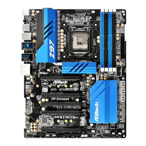
RoHS
Designed in Taipei
1
HD_AUDIO1
LAN
PHY
LAN
PHY
CLRCMOS1
1
JGP IO1
CPU_FAN1
DDR3_A1
DDR3_A2
CHA_FAN1
LPT1
SATA_PWR1
Top:
RJ-45
USB 2.0
T: USB0
B: USB1
Ps2
Mouse
Ps2
Keyboard
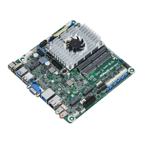
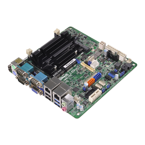
IMB-130
COM
Port A
COM
Port B
DC12V1
PWR_JP1
1
JGPIO_PWR1
1
LVDS1
SET_CM4
SET_CM6
SET_CM5
COM4
COM6
COM5
BLT_VOL1
1
USB6
22
23
24 25 26 27
USB4, 5
28
SPEAKER1
1
1
1
11 1
29 30
31
32
33
34
35
36
37
1
1
1
11
1
BLT_PWR2
1
VGA1
HDMI1
Top:
Line Out
Bottom:
Mic In
SET_CM2
SET_CM1
USB 2.0
T: USB2
B: USB3
PNL_PWR1
BKT_PWR1
JLVD_GPIO1
COM Port PWR Setting headers
22 : For COM Port2
23 : For COM Port1
27 : For COM Port4
28 : For COM Port5
29 : For COM Port6
Internal COM port connectors:
30 : COM Port4
31 : COM Port5
32 : COM Port6
24 : Speaker connector
25 : Panel BackLight Inverter connector
1,2=> GND
3=> Panel Backlight Control
4=> Panel Backlight Enable
5,6=> Panel Backlight Power
26 : Panel Brightness and Speaker Volume
control
Pin denition: 1=> Volume_UP
2=> Volume_DOWN
3=> PANEL PWR Down
4=> Panel BackLight UP
5=> Panel BackLight
Down
6=> GND
7=> GND
14
R- L+
R+ L-
16
Internal USB connectors
33 : USB Port4, 5
34 : USB Port6
37 : Panel resolution selection
The setting table
17
PWR - 5 +5 GND
PWR - 4 +4 GND
28
14
PWR -6 +6 GND
35 : Panel VDD PWR Setting
1-2: +3.3V
2-3: +5V
36 : Panel BackLight PWR Setting
1-2: +5V
2-3: +12V
Note: If you want to use BIOS to set Panel type,
then set all GPIO[3:0]= “1111”.
If you want to use jumpers to set Panel type,
select “Set by Jumper” in BIOS.
High + GPIOx = 1, Low + GPIOx = 0
1
3
5
7
9
2
4
6
8
10
COM7
WTOB_CON_2X5P
DDSR#_5
TTXD_5
RRTS#_5
DDTR#_5
CM5_P1
CM5_P9
RRXD_5
CCTS#_5

