EnglishDeutsch
 logo
Brands
  1. Home
  2. •
  3. Brands
  4. •
  5. ASROCK
  6. •
  7. Motherboard
  8. •
  9. ASROCK IMB-792 User instructions

ASROCK IMB-792 User instructions

Other manuals for IMB-792

1

Other ASROCK Motherboard manuals

ASROCK E3C224D4HM-8R User manual

ASROCK

ASROCK E3C224D4HM-8R User manual

ASROCK B450M Steel Legend User manual

ASROCK

ASROCK B450M Steel Legend User manual

ASROCK A75M User manual

ASROCK

ASROCK A75M User manual

ASROCK Z77 Extreme4 User manual

ASROCK

ASROCK Z77 Extreme4 User manual

ASROCK N68C-SE - V1.0 User manual

ASROCK

ASROCK N68C-SE - V1.0 User manual

ASROCK E35LM1 R2.0 User manual

ASROCK

ASROCK E35LM1 R2.0 User manual

ASROCK B460M-HDV User manual

ASROCK

ASROCK B460M-HDV User manual

ASROCK IMB-390-L Service manual

ASROCK

ASROCK IMB-390-L Service manual

ASROCK 939Dual-SATA2 User manual

ASROCK

ASROCK 939Dual-SATA2 User manual

ASROCK H81TM-ITX R2.0 User manual

ASROCK

ASROCK H81TM-ITX R2.0 User manual

ASROCK 770 Extreme3 User manual

ASROCK

ASROCK 770 Extreme3 User manual

ASROCK 785GM-GS3 User manual

ASROCK

ASROCK 785GM-GS3 User manual

ASROCK H81M-ITX User manual

ASROCK

ASROCK H81M-ITX User manual

ASROCK X58 EXTREME6 - User manual

ASROCK

ASROCK X58 EXTREME6 - User manual

ASROCK B150M-ITX/D3 User manual

ASROCK

ASROCK B150M-ITX/D3 User manual

ASROCK 880GM PRO3 User manual

ASROCK

ASROCK 880GM PRO3 User manual

ASROCK IMB-142 User manual

ASROCK

ASROCK IMB-142 User manual

ASROCK A780LM-S - V1.0 User manual

ASROCK

ASROCK A780LM-S - V1.0 User manual

ASROCK 890GM Pro3 R2.0 User manual

ASROCK

ASROCK 890GM Pro3 R2.0 User manual

ASROCK X38TURBOTWINS User manual

ASROCK

ASROCK X38TURBOTWINS User manual

ASROCK G41MH USB3 User manual

ASROCK

ASROCK G41MH USB3 User manual

ASROCK H310M-G/M.2 User manual

ASROCK

ASROCK H310M-G/M.2 User manual

ASROCK P4I945GC User manual

ASROCK

ASROCK P4I945GC User manual

ASROCK H61M-HVGS User manual

ASROCK

ASROCK H61M-HVGS User manual

Popular Motherboard manuals by other brands

DFI SD170 user manual

DFI

DFI SD170 user manual

Asus P2L97A user manual

Asus

Asus P2L97A user manual

Winmate IC70 user manual

Winmate

Winmate IC70 user manual

Asus MES-B user manual

Asus

Asus MES-B user manual

Grantech SYS8F377VGGA-3OMN user manual

Grantech

Grantech SYS8F377VGGA-3OMN user manual

Telit Wireless Solutions SL869-3DR user guide

Telit Wireless Solutions

Telit Wireless Solutions SL869-3DR user guide

Texas Instruments ADS8372EVM user guide

Texas Instruments

Texas Instruments ADS8372EVM user guide

Commell MS-C73 user manual

Commell

Commell MS-C73 user manual

Gigabyte GA-9IVDT user manual

Gigabyte

Gigabyte GA-9IVDT user manual

IBT Technologies MB860 user manual

IBT Technologies

IBT Technologies MB860 user manual

Nvidia TEGRA DG-04927-001_V01 user guide

Nvidia

Nvidia TEGRA DG-04927-001_V01 user guide

Intel D33217CK specification

Intel

Intel D33217CK specification

Asus F1A55-M LX PLUS R2.0 user manual

Asus

Asus F1A55-M LX PLUS R2.0 user manual

EPC EPC9147C quick start guide

EPC

EPC EPC9147C quick start guide

Asus EX-B760M-V5 D4 quick start guide

Asus

Asus EX-B760M-V5 D4 quick start guide

EPOX MU-8KHA0010 user manual

EPOX

EPOX MU-8KHA0010 user manual

Ski-Doo Bombardier MPEM 219 700 090 user guide

Ski-Doo

Ski-Doo Bombardier MPEM 219 700 090 user guide

Epson S5U13700P00C000 user manual

Epson

Epson S5U13700P00C000 user manual

https://manuals.online logo
https://manuals.online logoBrands
  • About & Mission
  • Contact us
  • Privacy Policy
  • Terms and Conditions

Copyright 2026 Manuals.Online. All Rights Reserved.

The terms HDMI™ and HDMI High-Denition
Multimedia Interface, and the HDMI logo are
trademarks or registered trademarks of HDMI
Licensing LLC in the United States and other
countries.
COM Port Pin9 PWR Setting Jumpers
17 : PWR_COM7 (For COM Port7)
PWR_COM8 (For COM Port8)
PWR_COM9 (For COM Port9)
PWR_COM10 (For COM Port10)
19 : PWR_COM3 (For COM Port3)
PWR_COM4 (For COM Port4)
PWR_COM5 (For COM Port5)
PWR_COM6 (For COM Port6)
1-2 : +5V
2-3 : +12V
18 : PWR_BAT1
Open : Normal
Short : Charge Battery
20 : Clear CMOS Header (CLRMOS1)
1-2 : Normal
2-3 : Clear CMOS
21 : PWR LOSS Header (PWR_LOSS1)
Short : Power Loss
Close : no Power Loss
22 : Chassis Intrusion Headers
CI1 :
Short
: Active Case Open
Open : Normal
CI2 :
Short
: Normal
Open : Active Case Open
23 :
USB 2.0 Header
(
USB2_5_6
)
7 : SATA3 Connectors (SATA3_1 ~ SATA3_4)
8 :
Chassis FAN Connector (+12V)
9 : MSATA Select (MSATA_SEL1)
Short
: Mini-SATA
Open : SATA3_2
10 : M2 Select (M2_SEL1)
Short
: M.2
Open : SATA3_1
11 : USB2_PWR3 (For USB2_10)
1-2 : +5V
2-3 : +5VSB
12 : Vertical Type A USB 2.0 Port (USB2_10)
13 : COM Port Headers
(COM3~10) (RS232)
14 : ATX/AT Mode Jumper
(PWR_JP1)
1-2 : AT Mode
2-3 : ATX Mode
15 :
System Panel Header
16 : Clear CMOS Header
(CLRMOS2)
Open : Normal
Short : Auto Clear CMOS (Power Off)
1 : ATX 12V Power Connector
2 :
CPU FAN Connector (+12V)
3 : M.2 Key-M Socket
4 :
24-pin ATX Power Input Connector
5 : USB3_PWR3 (For USB3_1_2)
1-2 : +5V
2-3 : +5VSB
6 : USB 3.0 Header
(
USB3_1_2
)
IMB-792
Jumpers and Headers Setting Guide
8 5
4 1
GND
+12V
CPU_FAN_SPEED
FAN_SPEED_CONTROL
ATXPWR1
DDR4_B1 (64 bit, 288-pin module)
DDR4_A1 (64 bit, 288-pin module)
PCI1
PCIE1
1
HD_AUDIO1
COM4
1
CMOS
Battery
HDLED RESET
PLED PWRBTN
PANEL1
1
CLRMOS1
1
CPU_FAN1
USB2_5_6
1
1
CI1
1
CI2
PWR_JP1
1
1
LPT_GPIO1
BUZZ1
mini-SATA
IMB-792
Top:
LAN2
USB 3.0
T: USB3
B: USB4
HDMI1
VGA1
ATX12V1
CHA_FAN1
COM3
1
SATA3_3
SATA3_4
SATA3_1
SATA3_2
LPC1
1
1
PWR_BAT1
JGPIO_SET1
1
Industrial
USB2_10
SPDIF1
1
JGPIO_PWR1
1
USB2_PWR1
1
1
PWR_COM4
1
PWR_COM3
1
PWR_COM6
1
PWR_COM5
USB2_PWR3
1
USB3_1_2
1
USB3_PWR3
1
1
PWR_COM1
1
PS2_PWR1
1
PWR_COM2
1
LAN_LED1
Top:
Line In
Center:
Line Out
Bottom:
Mic In
Top:
LAN1
USB 2.0
T: USB7
B: USB8
1
M2_SEL1
1
MSATA_SEL1
PCI2
PCI3
PCI4
PCI5
PCIE4
M.2 (Key-M)
1
LAN_LED2
1
USB_PWR2
1
LAN_LED3
1
LAN_LED4
1
USB3_PWR2
1
BUZZ2
1
PWR_COM7
1
PWR_COM8
1
PWR_COM9
1
PWR_COM10
CLRMOS2
1
COM6
1
COM5
1
COM8
1
COM7
1
COM10
1
COM9
1
1
PWR_LOSS1
COM1
COM2
PS2
Keyboard
PS2
Mouse
GND
RESET#
PWRBTN#
PLED-
PLED+
GND
HDLED-
HDLED+
1
GND
CCTS#1
COM PWR
DDSR#1
DDTR#1
RRXD1
GND
TTXD1
DDCD#1
1
RRTS#1
12
1
24
13
1
IntA_PB_D+
Dummy
IntA_PB_D-
GND
IntA_PB_SSTX+
GND
IntA_PB_SSTX-
IntA_PB_SSRX+
IntA_PB_SSRX-
VbusVbus
Vbus
IntA_PA_SSRX-
IntA_PA_SSRX+
GND
IntA_PA_SSTX-
IntA_PA_SSTX+
GND
IntA_PA_D-
IntA_PA_D+
DUMMY
GND
GND
P+
P-
USB_PWR
P+
P-
USB_PWR
1
GND
+12V
CHA_FAN_SPEED
FAN_SPEED_CONTROL
+5VSB_ATX
1
Signal
GND
P/ N: 15G06M065000AK V1.0
*15G06M065000AK*
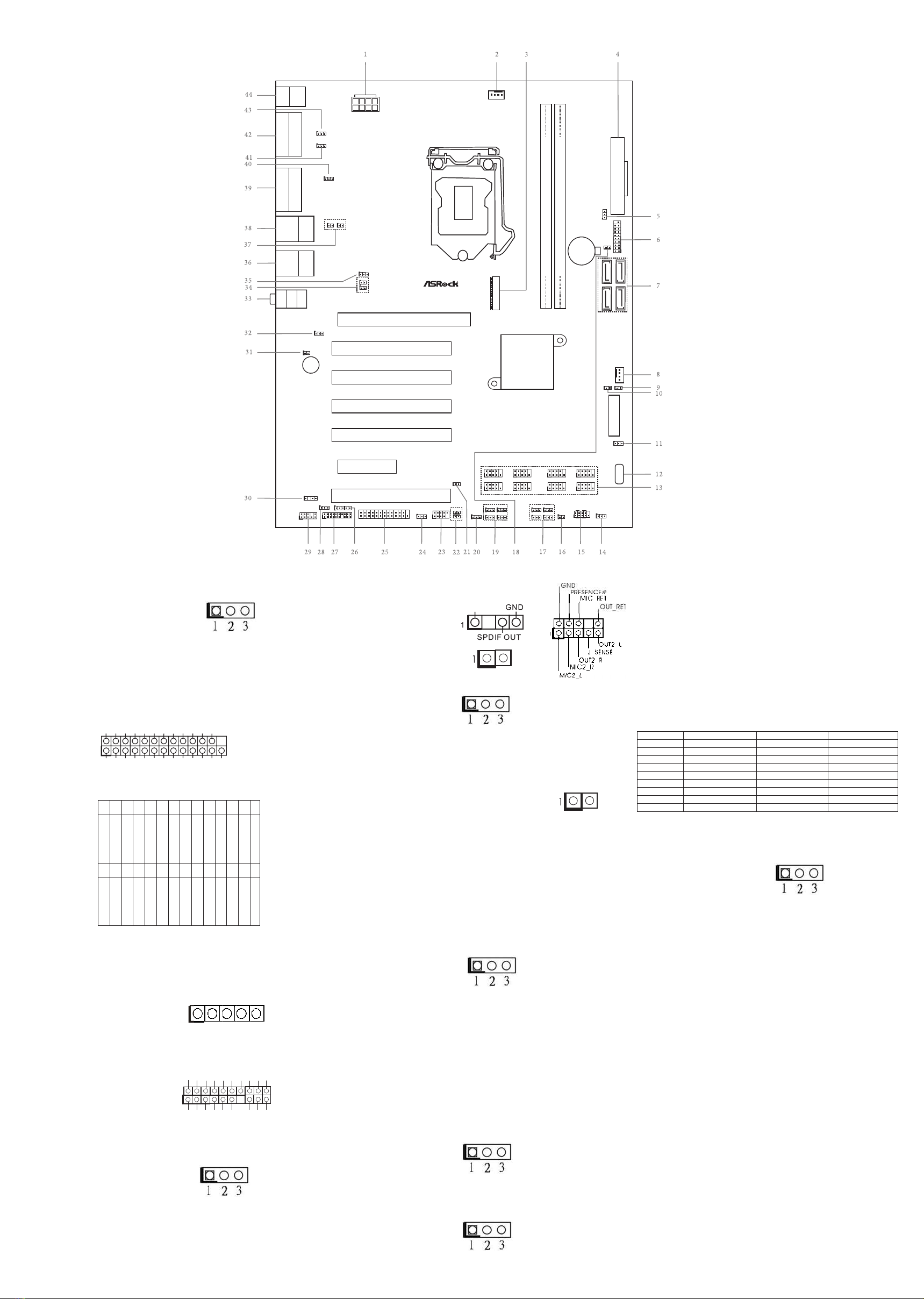
24 : USB2_PWR1 (For USB2_5_6)
1-2 : +5V
2-3 : +5VSB
25 : Printer Port / GPIO Header
(LPT_GPIO1)
Printer Port:
GPIO:
26 : Digital Input / Output Power Select
(JGPIOPWR) (JGPIO_PWR1)
1-2 : +12V
2-3 : +5V
3-4 : +5V
4-5: GND
27 : LPC Header
28 :
Digital Input / Output Power Select
(JGPIO_SET1)
1-2 : +5V
2-3 : GND
29 :
Front Panel Audio Header
30 : SPDIF Header
31 : Buzzer (BUZZ2)
32 : USB3_PWR2 (For USB3_3_4)
1-2 : +5V
2-3 : +5VSB
33 :
Audio Jacks
Blue - Line In
Green - Line Out
Pink - Mic In
LAN LED
Headers (LAN_LED1 ~ 4)
34 : LAN2 Speed LED Header (LAN_LED4),
LAN2 ACT/LINK LED Header
(LAN_LED3)
37 : LAN1 Speed LED Header (LAN_LED2),
LAN1 ACT/LINK LED Header
(LAN_LED1)
35 : USB_PWR2 (For USB2_7_8)
1-2 : +5V
2-3 : +5VSB
36 :
Top : RJ45 LAN Port (LAN2)
Bottom : USB 3.0 Ports (
USB3_3_4
)
38 :
Top : RJ45 LAN Port (LAN1)
Bottom : USB 2.0 Ports (
USB2_7_8
)
39 :
Top : VGA Port (VGA1)
Bottom : HDMI Port (HDMI1)
40 : COM Port Pin9 PWR Setting Jumper
(PWR_COM2 (For COM Port2))
1-2 : +5V
2-3 : +12V
41 :
PS2 Power Setting Jumper
(PS2_PWR1 (For PS2 Keyboard/Mouse))
1-2 : +5V
2-3 : +5VSB
ATXPWR1
DDR4_B1 (64 bit, 288-pin module)
DDR4_A1 (64 bit, 288-pin module)
PCI1
PCIE1
1
HD_AUDIO1
COM4
1
CMOS
Battery
HDLED RESET
PLED PWRBTN
PANEL1
1
CLRMOS1
1
CPU_FAN1
USB2_5_6
1
1
CI1
1
CI2
PWR_JP1
1
1
LPT_GPIO1
BUZZ1
mini-SATA
IMB-792
Top:
LAN2
USB 3.0
T: USB3
B: USB4
HDMI1
VGA1
ATX12V1
CHA_FAN1
COM3
1
SATA3_3
SATA3_4
SATA3_1
SATA3_2
LPC1
1
1
PWR_BAT1
JGPIO_SET1
1
Industrial
USB2_10
SPDIF1
1
JGPIO_PWR1
1
USB2_PWR1
1
1
PWR_COM4
1
PWR_COM3
1
PWR_COM6
1
PWR_COM5
USB2_PWR3
1
USB3_1_2
1
USB3_PWR3
1
1
PWR_COM1
1
PS2_PWR1
1
PWR_COM2
1
LAN_LED1
Top:
Line In
Center:
Line Out
Bottom:
Mic In
Top:
LAN1
USB 2.0
T: USB7
B: USB8
1
M2_SEL1
1
MSATA_SEL1
PCI2
PCI3
PCI4
PCI5
PCIE4
M.2 (Key-M)
1
LAN_LED2
1
USB_PWR2
1
LAN_LED3
1
LAN_LED4
1
USB3_PWR2
1
BUZZ2
1
PWR_COM7
1
PWR_COM8
1
PWR_COM9
1
PWR_COM10
CLRMOS2
1
COM6
1
COM5
1
COM8
1
COM7
1
COM10
1
COM9
1
1
PWR_LOSS1
COM1
COM2
PS2
Keyboard
PS2
Mouse
+5V
+ -
1
SPD0
STB#
SPD1
SPD2
SPD3
SPD4
SPD6
SPD7
GND
GND
SLIN#
PINIT#
ERROR#
AFD#
GND
GND
GND
GND
GND
GND
SPD5
ACK#
BUSY
PE
SLCT
*
If you want to use the printer port function, please
short pin4 and pin5 on
Digital Input / Output Power Select (JGPIO_PWR1).
PIN Signal Name PIN Signal Name
26 NC 25 NA
24 GND 23 SIO_GP30
22 GND 21 SIO_GP31
20 GND 19 SIO_GP32
18 GND 17 SIO_GP33
16 GND 15 SIO_GP34
14 GND 13 SIO_GP35
12 JGPIOPWR 11 SIO_GP36
10 JGPIOPWR 9 SIO_GP37
8 SIO_GP43 7SIO_GP40
6 SIO_GP44 5 SIO_GP41
4 SIO_GP45 3 SIO_GP42
2SIO_GP46 1SIO_GP47
1
1
GND
GND
S_PWRDWN#
LAD2
SMB_CLK_MAIN
PCICLK
PCIRST#
LAD3
+3V
LAD0
GND
FRAME
SMB_DATA_MAIN
LAD1
SERIRQ#
GND
+3VSB
48MHz +5V
42 :
Top : COM Port (COM1)
(RS232/422/485)*
Bottom : COM Port (COM2)
(RS232/422/485)*
43 : COM Port Pin9 PWR Setting Jumper
(PWR_COM1 (For COM Port1))
1-2 : +5V
2-3 : +12V
44 :
Top : PS/2 Mouse Port
Bottom : PS/2 Keyboard Port
* This motherboard supports RS232/422/485 on COM1, 2 ports.
Please refer to below table for the pin denition. In addition, COM1, 2
ports (RS232/422/485) can be adjusted in BIOS setup utility >
Advanced Screen > Super IO Conguration. You may refer to our
user manual for details.
COM1, 2 Port Pin Denition
PIN RS232 RS422 RS485
1 DCD, Data Carrier Detect TX- RTX-
2RXD, Receive Data RX+ N/A
3 TXD, Transmit Data TX+ RTX+
4 DTR, Data Terminal Ready RX- N/A
5 GND GND GND
6 DSR, Data Set Ready N/A N/A
7RTS, Request To Send N/A N/A
8 CTS, Clear To Send N/A N/A
9 No Power/5V/12V N/A N/A