Astor-Bannerman ABW6SP Troubleshooting guide

Warranty No
Height Adjustable Basin
ABW6SP
OWNERS MANUAL & INSTALLATION GUIDE

Page: 2 Version 2 : 11-04-2016
Operation
HO
T
D
O
WN
U
P
L
I
G
H
T
P
L
U
G
C
O
L
D
Press and hold button
to raise basin
Press and hold button
to lower basin
Press and release button
to turn Hot water on or off
Press and release button
to turn Cold water on or off
Press and release button
to raise or lower plug
Press and release button
to turn light on or off
Following functions apply to the SP
version only

Page: 3 Version 2 : 11-04-2016
Caution: The unit is fitted with a safety mechanism, if the unit encounters an obstruction
under the front portion of the basin whilst travelling downwards it will automatically stop.
Pressing the ‘Up’ button will allow the obstruction to be removed. Care should be taken
to ensure that whilst the basin assembly is moving downwards there are no obstructions
left directly beneath the basin or rise & fall unit as the safety mechanism is designed to stop the unit
only when the front of the basin is lifted.
If both the ‘Up’ and Down’ buttons are pressed at the same time the unit will not move.
Cleaning
The basin and vanity top may be cleaned using most mild cleaning agents. Chemical agents must
not be used, i.e., drain cleaners, acetone, oven cleaners or acids. The rise and fall unit, mirror and
handset should be cleaned using a warm soapy solution and rinsed with a damp cloth. Attention
should always be paid to instruction labels on the outside of cleaning agent containers.
Manual operation of the lever tap system
In normal operation the levers should be facing forward, (towards the user) when off. To operate
them, rotate the levers outwards to achieve the flow-rate required. To stop water flowing, rotate the
levers until they are facing forward once again.
The waste plug
To the rear of the tap block is a small rod with a ‘knob’ fitted to the top. This can be raised and
lowered to open or close the waste plug as required.
Operating the touch tap system
The taps are usually set as wave ON-Wave OFF.
To turn the water ON /OFF pass your hand above the Sensor on the basin top.
Touch Tap
Sensors
in position

Page: 4 Version 2 : 11-04-2016
Technical Specification.
Duty cycle: 10%, Maximum 2 min/18 min
IP Rating: IP X4
Supply voltage: 230V ac
# Item No. Item Description Qty
1 20.040.20.0005 Taps, lever handles, 1
2 20.040.30.0010 Hose, 1400mm, 3/4 BSP & 90 degree Conex fittings
(ABW6)
2
3 21.090.00.0029 Washer, 3/4 Gauze filter 2
4 75.090.00.0039 Washer, fibre 1/2 2
5 75.090.00.0060 Washer, M8, Form C (wide) stainless steel, 3
6 20.032.00.0003 Holder, handset 1
7 20.040.50.0006 Handset, ABW6, grey, 6 button, 1
8 10.041.00.0021 Tube, copper 70mm ABW6sp 2
9 10.041.00.0020 Tube, copper 45mm ABW6sp 6
10 21.090.00.0390 Tie, cable, 12 (300mm) 1
11 20.041.90.0001 Hose kit,2pr 300x550mm,1/2 flat,15mm brass tube
ABW6sp
1
12 10.041.30.0002 Plug actuator assembly 1
13 20.040.30.0008 Connector, 15mm - 1/2 in brass,303 SF 2
14 20.040.30.0009 Connector, 15mm, compression, brass T 4
15 20.041.00.0018 Elbow, 15mm conex, 2
16 21.090.00.0258 Valve,solenoid,12volt,plastic,nuts,olives,15mm 2
Power 0.25KW
Dry weights: 50Kg.
A weighted sound emission<70dB(A)
Contents of Packages

Page: 5 Version 2 : 11-04-2016
*
C
L
Plumbing:
Fit cold (on left) and hot (on right) outlets, terminating with 3/4” BSP washing machine isolation
valves, pointing upwards at 150mm maximum above the floor and offset to the left of the centre
line of the unit by 125mm. These feeds will be enclosed by 50x75mm trunking upon installation. An
1¼” waste pipe needs to be fitted at 150mm maximum above the floor, offset to the right of the
centre line of the unit by 80mm.
Electrics:
The ABW6 is supplied with mains electric (230v) and transformed to 24v within the unit. A battery
backup is fitted as standard. A 30mA RCD protected fused spur is required, with flush mounted a
flex outlet cover, on the wall behind the unit at a height of 1100mm from the floor on the centreline
of the unit.
Fixing:
The basin assembly should be fixed to a load bearing wall (i.e. strong enough to carry a 100kg load
on wall fixing) which is flat and free from obstruction from 200mm – 2200mm above the floor. If
the basin needs to be fixed to a stud wall, the wall will need special reinforcement, either noggins
as shown above or 25mm (1 inch) marine or exterior plywood should be used to cover the entire
fixing area, secured to the wall every 200mm.
Flush mounted fused spur
with flex outlet cover
fixed 1100 above floor
on the centre line of the unit
¾” BSP Washing
machine valves
150mm
Maximum
Cold
Supply
Hot
Supply
1¼”
Waste
80mm
800mm
Lower
Fixing
1200mm
Upper Fixing
125mm
Installation information.

Page: 6 Version 2 : 11-04-2016
Please Note: Due to the complexity of different building methods Astor
Bannerman do not supply installation fixings and anchors.
Important: The attachment rail is the main load bearing fixing; it is vital that it is secured
correctly .
Measure 1200mm up from the floor along the centre-line of the final position of the unit; using a
spirit level, draw a horizontal line at least 520mm long.
Place the attachment rail with the open lip upwards, on the line. With a pencil mark two of the
holes for the rail at least 250mm apart
Using a masonry bit, drill two 6mm full depth pilot holes at the marked positions and then open up
in order to accept the Anchors.
Centre of fixing holes
1200mm above Floor
Fix the attachment rail, open lip
uppermost to the wall using suitable
fixings.
Ensure that the rail is level using a spirit
level (adjust to suit) and check that it is
secure.
With assistance, place the rise and fall unit
onto the wall ensuring that the two short
rails welded to the unit engage with the
one on the wall.
Ensure that the unit is level, then mark
the wall through the remaining three
attachment points, two on the lower
horizontal beam and one on the upper
horizontal beam
Remove the unit from the wall and at the
three marked positions drill three 6mm full-depth pilot holes.
Open the upper hole to accept a plastic wall plug.
Fit supporting Anchors in the two lower holes
Place the rise and fall unit back onto the wall-mounted rail. Fully fix the rise and fall unit to the
wall.
Ensure that the mains supply to the junction box on the wall is switched OFF.
Electrically connect the rise and fall unit to fused outlet behind the unit with the three-core cable
supplied.
Lower the arms and ensure the handset is fitted BEFORE switching the power on
•
•
•
•
•
•
•
•
•
•
•
•
•

Page: 7 Version 2 : 11-04-2016
Switch on the mains voltage, a light fitted next to the
Handset socket on the right hand side of the unit,
should be illuminated.
Test the Safety Switch mechanism on the arms
works properly.
Operate the lowering function and then lift the right
hand arm to ensure the motor cuts out.
Leave the mains voltage supply switched on as it will
allow the batteries to charge.
Remove the ‘P’ Trap & straight coupling from the waste
assembly.
Fit the waste and cable tie in position as shown.
Assemble the Basin:
Cover the support arms to protect the Basin.
Rotate the support arms so they are horizontal and place the up turned basin on the arms.
Fit the tap bodies to the basin as shown. Ensure there is 35mm of threaded body showing above
the basin deck to allow fitting the handle. Ensure the nylon washer is fitted under the handle
screw to remove any clearance on the spline.
Fit the 1/2”-15mm tap adaptors
Fit the spout in position and connect the flexible hoses as shown.
Fit the overflow, hose and waste connection into the basin, apply a thin film of silicon sealant to
the faces to assist with sealing
Using the adjusting screw, set the overall length of the basin plug to 77mm.(may need adjusting
later)
Fit the plug operating actuator.
Attach the mounting bracket using 2 screws.
Stand the lower cover in place, then:-
Fit the horizontal plug lifting rod in position and set the clamp to lift the plug. See measurements.
•
•
•
•
•
•
•
•
•
•
•
•
•
•
•
•

Page: 8 Version 2 : 11-04-2016
30mm
50MM
HOT INLET
COLD INLET
SPOUT
into
BASIN
Pipe connection diagram
Sloenoid
Sloenoid
Tap
body
Tap
body

Page: 9 Version 2 : 11-04-2016
Leave the clamp in place, fit the vertical rod
Fit the water supply solenoids.
Ensure the direction of flow, indicated by an arrow on the solenoid body, is correct this should
point towards the deck of the basin.
Connect the wiring to the actuator and water solenoids. Labels indicating the wire
positions are on the side of the electrical control box.
Touch taps:
Fit the sensors before mounting the unit on the wall
Touch tap sensors should be fitted in the position agreed with the client.
Drill an 18mm in the position required, take care to avoid items under the basin.
Position the coloured ring on the sensor and fit the securing nut.
Position the second sensor.
Wire the sensors into the control box behind the mirror
The basin assembly is now ready to be fitted to the high low frame .
Remove the protective film from double-sided sticky tape fitted to the pivoting arms and place the
basin onto the support arms as far back as possible, ensuring the basin is under the white plastic
upper cover which holds the mirror.
COLD
SUPPLY
HOT
SUPPLY
Hoses
Rear view
The mains water supply can now be fitted.
Ensure both the hot and cold mains water supplies have been flushed and only then fit the open
ends of the supply hoses with the filter screens supplied onto the isolation valves.
Ensure the free end of the supply hoses are passed through the recess in the bottom left hand
side of the carcass of the rise and fall unit.
Connect the end of the supply hoses with the Conex fitting to the tap connectors.
Test the water supply:
Ensure the isolation valves are CLOSED. Place a bucket or suitable container below the plug
hole of the basin. Open both basin taps fully and then slowly open each of the isolation valves,
wait 2 minutes, then examine the supply system for leaks, correct as necessary. Close the
isolation valves.
Fit the white plastic lower cover:
Remove the mushroom heads from the plastic rivets and place aside, fit the bodies into the six
holes in the frame
Remove the P Trap and straight coupling from the waste assembly.
Feed the free end of the flexible hose through the cut out in the lower right hand side of the
•
•
•
•
•
•
•
•
•
•
•
•
•
•
•
•
•
•

Page: 10 Version 2 : 11-04-2016
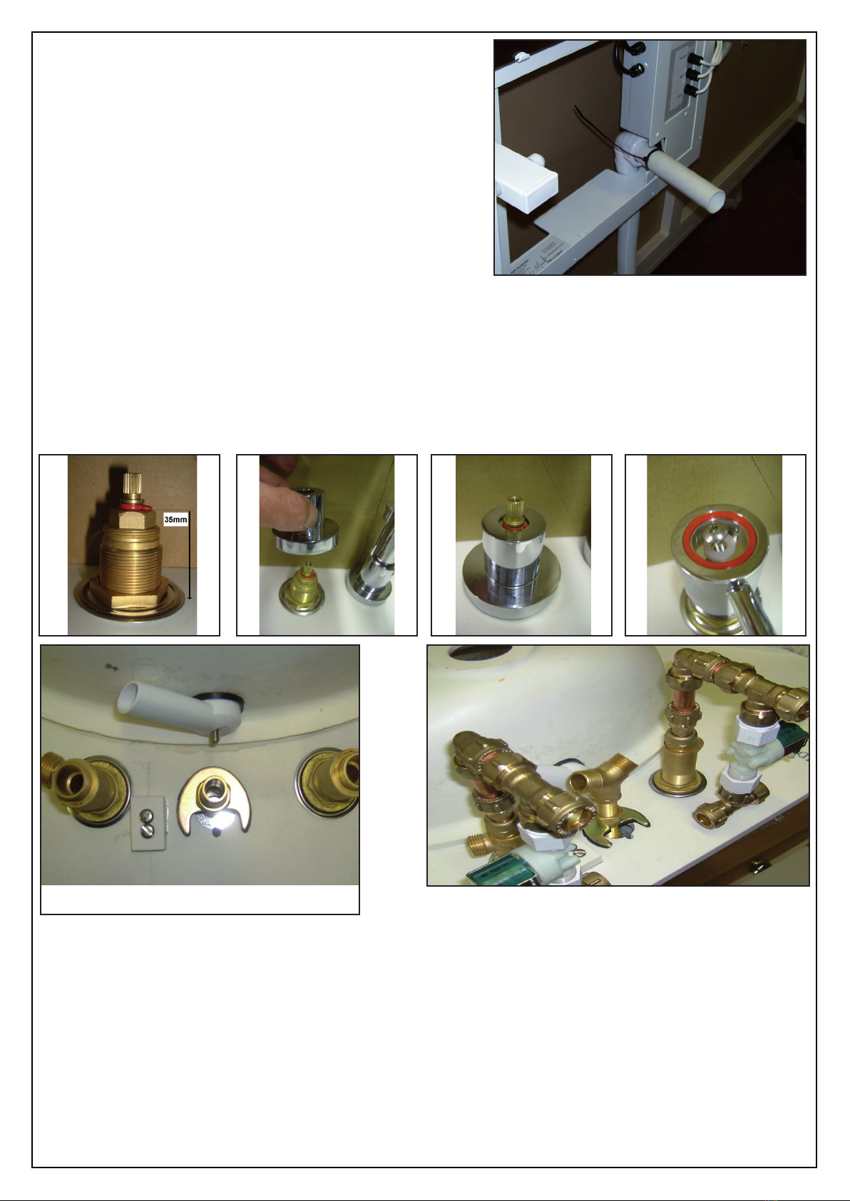
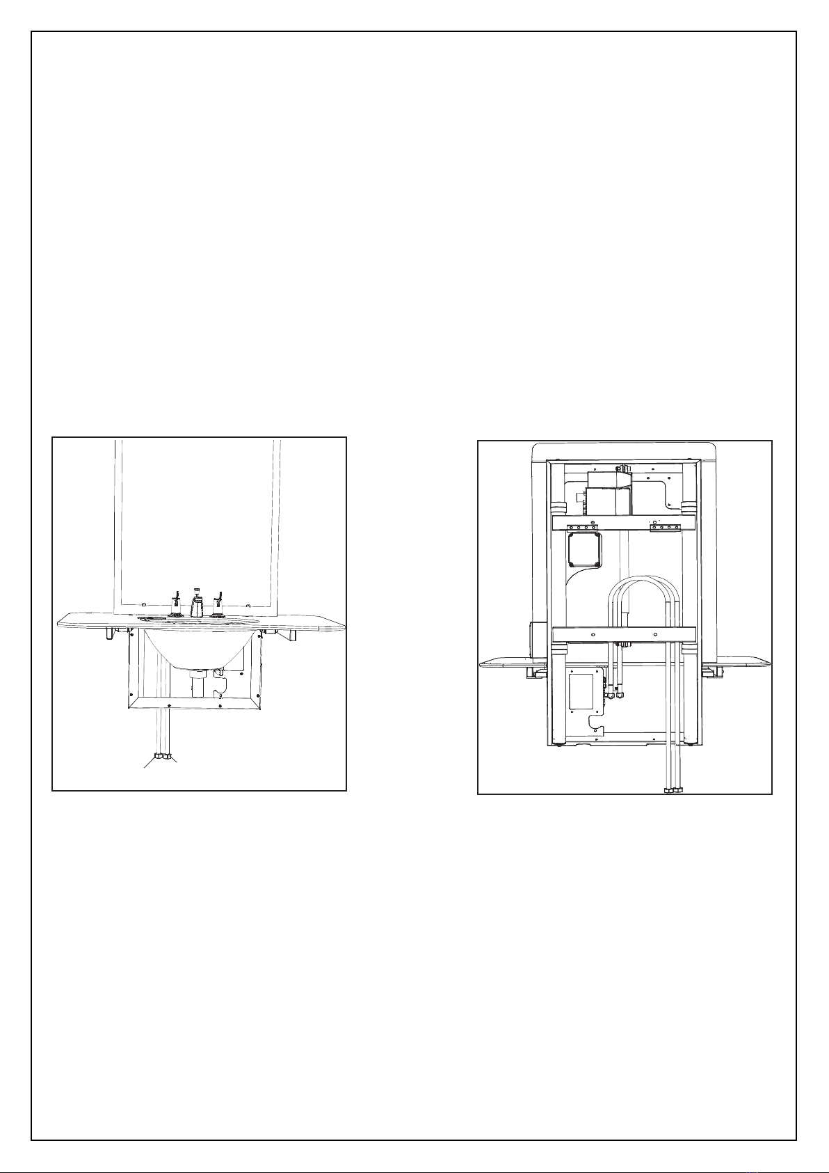
Working through the aperture in the base of the cover, support the waste assembly, fit the nut
and seals from the P trap through the front hole in the cover and then connect to the P trap
Connect the P Trap to the underside of the basin.
Fit the free end of the flexible hose to the waste pipe fitted to the site as part of the pre
installation preparations and secure with a cable tie as shown in the picture on page 5.
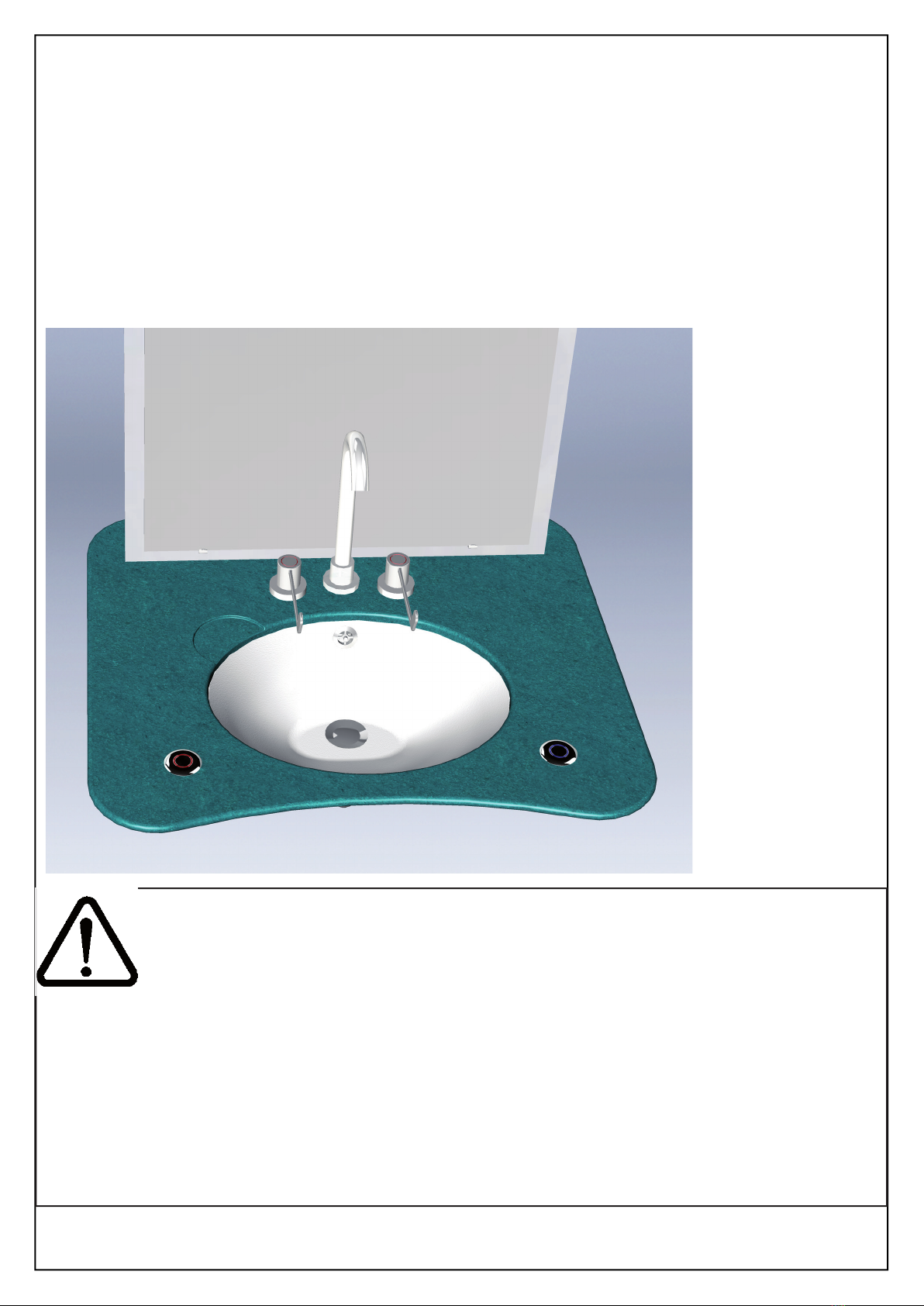
Rod
Adjuster
Basin viewed from below
Rod
Adjuster
Basin viewed from below
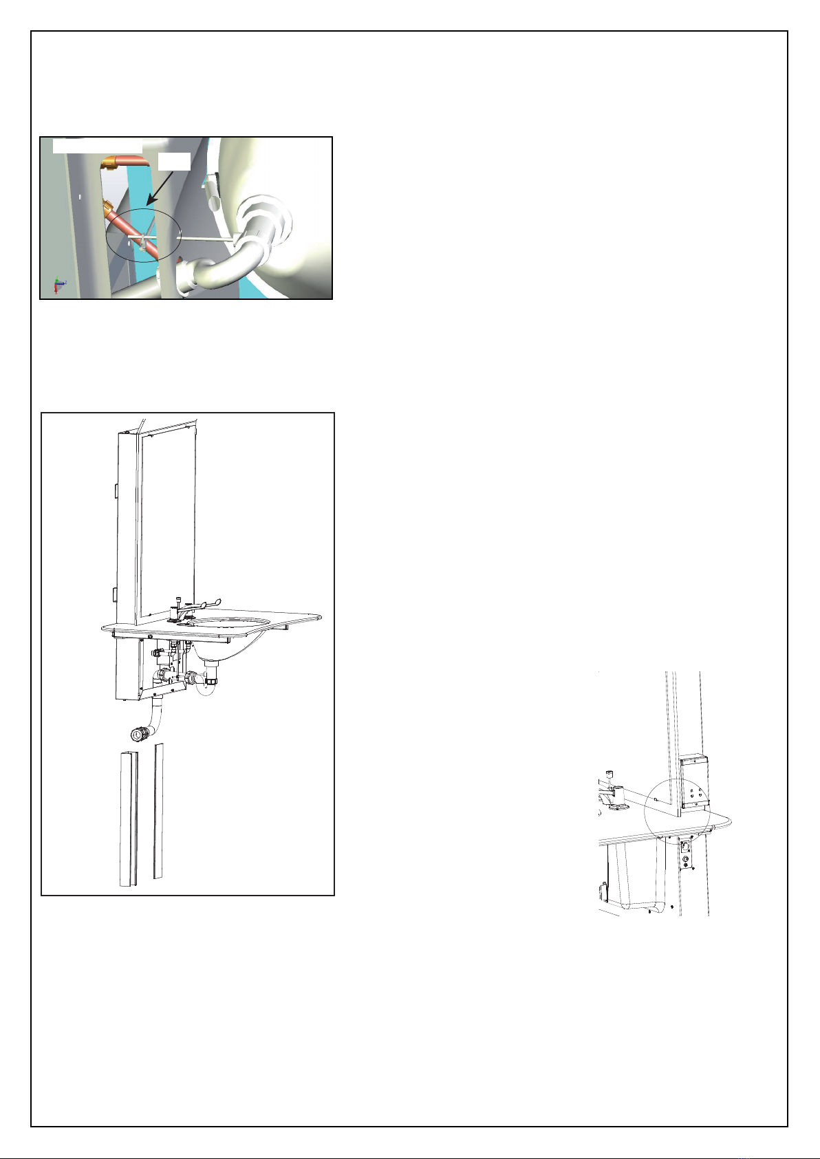
Adjustments to the screw on the pop-up waste plug
base and clamp for the rods may be necessary to ensure maximum lift of the waste plug. Access
to the clamp may be gained through the large hole in the base of the white plastic lower cover
Fit the Trunking:
The hot and cold supply hoses need to be enclosed
within the white self adhesive trunking supplied.
Using the handset, raise the assembly to its highest
position
Remove the capping from the front of the trunking.
Remove the protective film from the self adhesive tape
fitted to the rear of the trunking.
Pass the trunking behind the hot and cold supply hoses
taking care to ensure that the self adhesive tape is kept
away from the wall at this time. The top of the trunking
needs to be aligned with the recess in the bottom left
hand side of the rise and fall unit; through which were
passed the supply hoses earlier.
Using a level, ensure the
trunking is vertical. Once
aligned, press the self adhesive
tape against the wall to secure
the top of the trunking. Then
press the entire length of the
trunking into position.
Fit the capping.
Fit the mirror:
Remove the two white plastic
caps from above the top mirror
clips and remove the screws.
Place the bottom edge of the mirror into the lower catches and hold
in a vertical position. Ensure the mirror is fitted centrally. Gently push the uppermost catches
downwards into position such that they retain the mirror in its correct position. Fit the 2
security scews .
Test the unit:
Operate the handset to raise and lower the basin over the full range of travel to ensure there
is clearance between all moving surfaces. Examine for evidence of leaks correct as necessary,
examine and clean the assembly. Complete the warranty documentation and pass the completed
warranty document to the client.
•
•
•
•
•
•
•
•
•
•
•
•
•
•
•

Page: 11 Version 2 : 11-04-2016
Troubleshooting
In the unlikely event that problems occur with the unit, carry out the following easy
checks to determine whether or not an engineer is required.
Fault: The rise and fall unit does not travel up or down
Cause: The mains power supply has been disconnected for some time and the unit’s
batteries are now flat.
Remedy: Examine the light fitted to the right hand side of the unit. If the light is not
illuminated neither mains electricity nor battery backup are supplying the
unit. Examine the mains fuses/circuit breakers and reset as necessary and
ensure that mains voltage is fully reconnected then press the reset button
situated next to the handset connector. If the light fails to illuminate further
assistance will be required
Fault: The rise and fall unit travels upwards but not downwards.
Cause: There is an obstruction underneath the basin or the microswitch is not
engaged
Remedy: Depress the ‘Up’ button on the handset to gain clearance from the
obstruction and then remove the obstruction. The rise & fall unit may then
resume normal function. Check that the micro switch makes and breaks the
safety circuit when the rim of the basin is lifted slightly.
If the problem persists after carrying out these remedies, please
contact Astor-Bannerman using the details on the rear cover of this booklet.

Astor Bannerman (Medical) Limited
Unit 11f Coln Park, Andoversford, Cheltenham, GL54 4HJ
T: +44 (0)1242 820820
F: +44 (0)1242 821110
Technical Helpline - 01242 822972
© 2013 Astor Bannerman (Medical) Limited.
Our policy is one of continuous development, and we therefore reserve the right to make technical
alterations without notice. The content of this publication may not be copied either whole or in part
without the consent of Astor Bannerman (Medical) Limited
Original Document
Table of contents
Popular Plumbing Product manuals by other brands

Premier
Premier 120125 Installation

Hans Grohe
Hans Grohe Metris Series Instructions for use/assembly instructions

Axor
Axor Starck 10030XX1 Installation instructions / warranty

FM Mattsson
FM Mattsson FMM 9397 Instruction

Delabie
Delabie 130320 manual

Hansgrohe Axor
Hansgrohe Axor Montreux 16540 Instructions for use/assembly instructions