manuals.online logo
Brands
  1. Home
  2. •
  3. Brands
  4. •
  5. Schell
  6. •
  7. Plumbing Product
  8. •
  9. Schell COMPACT HF 01 165 00 99 Instruction manual

Schell COMPACT HF 01 165 00 99 Instruction manual

Made in Germany
SCHELL Urinalsteuerung COMPACT HF
DMontage- und Installationsanleitung
Urinalsteuerung COMPACT HF
230 V - Art.-Nr. 01 165 00 99
9 V - Art.-Nr. 01 166 00 99
Zubehör
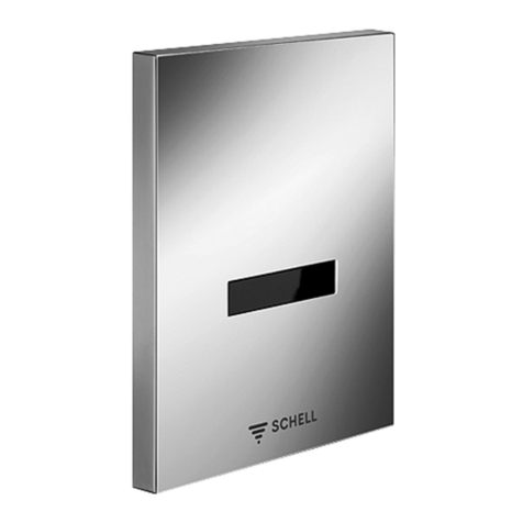
Urinal-Frontblende EDITION Art.-Nr.: 23 080 28 99
Verlängerungskabel (1 m) Art.-Nr.: 01 484 00 99
Verlängerungskabel (5 m) Art.-Nr.: 01 471 00 99
NL Montage- en installatiehandleiding
urinoirsturing COMPACT HF
230 V - Art.-nr. 01 165 00 99
9 V - Art.-nr. 01 166 00 99
Toebehoren
Urinoir frontplaat EDITION Art.-nr: 23 080 28 99
Verlengkabel (1 m) Art.-nr: 01 484 00 99
Verlengkabel (5 m) Art.-nr: 01 471 00 99
FInstructions de montage et d‘installation
de la commande pour urinoir COMPACT
HF
230 V - Réf. 01 165 00 99
9 V - Réf. 01 166 00 99
Accessoires
Plaque frontale pour
urinoir EDITION Réf.: 23 080 28 99
Câble de rallonge (1 m) Réf.: 01 484 00 99
Câble de rallonge (5 m) Réf.: 01 471 00 99
GB Assembly and installation
instructions for the COMPACT HF
urinal control
230 V - Item no. 01 165 00 99
9 V - Item no. 01 166 00 99
Accessories
EDITION urinal front panel Item no.: 23 080 28 99
Extension cable (1 m, 3.28 ft) Item no.: 01 484 00 99
Extension cable (5 m, 16.4 ft) Item no.: 01 471 00 99



– 2 – – 3 –
Technische Daten / Funktionsprinzip
Technische Daten
Fließdruck: 0,5 - 5 bar
Durchfluss: 0,3 l/s
Stromversorgung 230 V/50 Hz
Batteriebetrieb: 6 x 1,5 V Mignon
Batterien
Geräuschklasse II
Schutzart: IP 54
E-Modul und Sensor: Konformität nach
R & TTE 1999/05/EG, EMV 89/336/
EWG
HF-Leistung < 5 mW
Funktionprinzip
Das System erkennt die Bewegung des
Flüssigkeitsstrahls auf der Beckeninnen-
wand.
Es bestehen keine Auswirkungen von
Umgebungseinflüssen wie Licht, vorbei-
gehende Personen oder einem zu gerin-
gen Installationsabstand (Wand) etc.
Die Hygienespülung verhindert das
Austrocknen des Siphons.
Sensor
Nutzer
Sensorbereich
Die Bauteile der SCHELL HF-Urinal-
steuerung können in
– SCHELL COMPACT II Rohbauset
Art.-Nr.: 01 193 00 99
– SCHELL Urinal-Montagemodul
COMPACT II / COMPACT II HF/LC
Art.-Nr.: 03 282 00 99 /
03 283 00 99
installiert werden.
Zubehör
– Urinal-Zulaufgarnitur mit RV
(Art.-Nr.: 03 112 00 99)
– Frontblende EDITION
(Art.-Nr.: 23 080 28 99)
D
– 2 – – 3 –
Aansluitwaarden / Werkingsprincipe,
Valeurs de raccordement / Principe de fonctionnement
Valeurs de raccordement
Pression dynamique: 0,5 - 5 bar
Débit: 0,3 l/s
Alimentation électrique 230 V/50 Hz
Fonctionnement sur piles: 6 x piles Mignon 1,5 V
Classe sonore II
Degré de protection: IP 54
Module électronique et capteur:
conformité à R & TTE 1999/05/CE,
CEM 89/336/CEE
Puissance < 5 mW
Principe de fonctionnement
Le système détecte le mouvement du jet de
liquide sur la paroi intérieure de l’urinoir.
Les conditions ambiantes, telles que la lumière,
les personnes qui passent devant ou une dis-
tance d’installation trop faible (mur), etc., n’ont
aucune influence sur le système.
Le rinçage d’hygiène empêche un assèchement
du siphon.
capteur
utilisateur
zone du capteur
Les composants de la commande d’urinoir
SCHELL HF peuvent être installés dans
– Set à encastrer SCHELL COMPACT II
Réf.: 01 193 00 99
– SCHELL urinoir-montagemodule
COMPACT II / COMPACT II HF/LC
Réf.: 03 282 00 99 /
03 283 00 99
Accessoires
– Garniture d’alimentation pour urinoir avec
clapet anti-retour
(Réf.: 03 112 00 99)
– Plaque frontale EDITION
(Réf.: 23 080 28 99)
Aansluitwaarden
Waterdruk: 0,5 - 5 bar
Debiet: 0,3 l/s
Voeding 230 V/50 Hz
Batterijvoeding: 6 x 1,5 V Mignon-batterijen
Geruisklasse II
Beschermingsgraad: IP 54
E-module en sensor: conformiteit overeenkoms-
tig R & TTE 1999/05/EG,
EMV 89/336/EEG
Vermogen < 5 mW
Werkeringsprincipe
Het systeem herkent beweging van de vloeistof-
straal op de binnenwand van het urinoir.
Er zijn geen omgevingsinvloeden, zoals licht,
voorbijgaande personen of een te geringe instal-
latieafstand (muur) enz.
Automatische spoeling voorkomt uitdrogen van
de sifon.
sensor
gebruiker
sensorbereik
De onderdelen van de SCHELL HF-urinoirsturing
kunnen in:
– SCHELL COMPACT II inbouwset
Art.-nr.: 01 193 00 99
– SCHELL urinoir-montagemodule
COMPACT II / COMPACT II HF/LC
Art.-nr.: 03 282 00 99 /
03 283 00 99
worden geïnstalleerd.
Toebehoren
– Urinoirtoevoergarnituur met TK
(Art.-nr.: 03 112 00 99)
– Urinior frontplaat EDITION
(Art.-nr.: 23 080 28 99)
NL F



– 4 – – 5 –
Technical specifications / Functional principle
Technical specifications
Flow pressure: 0,5 - 5 bars
Flow: 0,3 l/sec
Power supply 230 V/50 Hz
Battery operation: 6 x 1,5 V batteries
(type Mignon)
Noise classification: class II
Protection class: IP 54
E-module and sensor: Conformity in
accordance with R & TTE 1999/05/EC,
EMC 89/336/EEC
HF-power output < 5 mW
Functional principle
The system detects the movement of
liquid on the inside of the urinal bowl.
Other influences of the environment
such as light, people passing or an instal-
lation distance too small (from the wall)
do not trigger flushing.
Hygienic flushing prevents the siphon
from drying out.
sensor
user
sensor area
Components of the SCHELL HF (High
Frequency) Urinal control are suited for
integration into:
– SCHELL COMPACT II roughing-in set
Item no.: 01 193 00 99
– SCHELL urinal mounting module
COMPACT II / COMPACT II HF/LC
Item no.: 03 282 00 99 /
03 283 00 99
Accessories
– Urinal inlet connection kit with back-
flow preventer
(Item no.: 03 112 00 99)
– EDITION front panel
(Item no.: 23 080 28 99)
GB
8sec
2-15
sec
6-10
sec
> 5 Nutzer/3 min
Spülen alle 60 s
8sec
2-15
sec
6-10
sec
> 5 Nutzer/3 min
Spülen alle 60 s
8sec
2-15
sec
6-10
sec
> 5 Nutzer/3 min
Spülen alle 60 s
8sec
2-15
sec
6-10
sec
> 5 Nutzer/3 min
Spülen alle 60 s
8sec
2-15
sec
6-10
sec
> 5 Nutzer/3 min
Spülen alle 60 s
8sec
2-15
sec
6-10
sec
> 5 Nutzer/3 min
Spülen alle 60 s
1
3
5
2
4
6
– 4 – – 5 –
Funktionsablauf / Functieverloop / Mode de fonctionnement /
Functional process
1. Nutzung.
2. Reaktionszeit ~ 8 s
3. Spülung 2 - 15 s (einstellbar s.S. 15)
4. Sperrzeit ca. 6 - 10 s (nachlaufendes
Wasser)
5. Bei verstopften Becken keine Spülung
(Überlaufschutz)
6. Start Stadionbetrieb:
Bei > 5 Nutzungen innerhalb von
3 Minuten = 1 Spülung / Minute
Stopp Stadionbetrieb automatisch:
Keine Nutzungen innerhalb von einer
Minute = Normalbetrieb
1. Gebruik.
2. Reactietijd ~ 8 s
3. Spoeling 2 - 15 s (instelbaar zie p. 15).
4. Spertijd ca. 6 – 10 s (nalopend water).
5. Geen spoeling als het urinoir verstopt
is (bescherming tegen overlopen).
6. Start stadionfunctie: Bij > 5 keer ge-
bruik binnen 3 min = 1 spoeling / min
Stop stadionfunctie: Geen gebruik
gedurende 1 min = normale functie.
1. Utilisation.
2. Temps de réaction ~ 8 s
3. Rinçage 2 - 15 s. (réglable cf. page 15)
4. Temps de blocage, env. 6 à 10 s
(eau courante).
5. Si l’urinoir est bouché, pas de rinçage
(protection contre le débordement).
6. Démarrage du mode stade:
S’il y a > 5 utilisations dans un délai
de 3 min = 1 rinçage / min
Arrêt du mode stade: S’il n’y a pas
d’utilisations pendant un délai d’une
minute = mode normal.
1. Use of urinal.
2. Response time ~ 8 s
3. Flushing 2 - 15 sec. (adjustable
cf p. 15).
4. Flush time approx. 6 - 10 s (run-on
time).
5. No flushing when urinal bowl is
blocked (overflow protection)
6. Start of stadium operation:
5 or more uses within a time period
of 3 min = 1 flush / min
Stop stadium operation: No uses
within 1 min = normal operation.
D
NL
F
GB







*






1
2
3
– 6 – – 7 –
Montagebeispiele
Montagebeispiele
1
Wasserstrecke oberhalb des Urinals*
2 Wasserstrecke hinter dem Urinal
3
Frontblende EDITION
montieren
(Art.-Nr.: 23 080 28 99)
Netzteil
Batteriefach
Magnetventil
E-Modul
Urinal-Zulaufgarnitur *
Verlängerungskabel Sensor (Zubehör)
HF-Sensor

Frontblende EDITION (Zubehör)
*Zulaufgarnitur mit RV installie-
ren, wenn das Rohbauset höher
als 1 m über der Zulaufgarnitur
montiert ist.
D
– 6 – – 7 –
Montagevoorbeelden / Exemples de montage / Assembly examples
Montagevoorbeelden
1 Kraanlichaam boven urinoir *
2 Watertraject achter het urinoir
3
Frontplaat EDITION
monteren
(Art.-nr.: 23 080 28 99)
Voeding
Batterijvak
Magneetventiel
E-module
Urinoir-toevoergarnituur *
Verlengkabel sensor (Toebehoren)
HF-Sensor

Frontplaat EDITION (
Toebehoren
)
*Toevoergarnituur met RV installeren
art.-nr. 03 112 00 99 (toebehoren), als
de inbouwset hoger dan 1 m boven de
toevoergarnituur gemonteerd is.
Exemples de montage
1 Canalisation d’eau au-dessus de l’urinoir *
2 Canalisation d‘eau derrière l‘urinoir
3 Monter plaque frontale
EDITION
(Réf.: 23 080 28 99)
Bloc d’alimentation
Compartiment à piles
Vanne magnétique
Module électronique
Garniture d’alimentation *
Rallonge capteur (accessoire)
Capteur HF
Plaque frontale EDITION
(
accessoire
)
* Installer la garniture d‘alimentation
avec le clapet anti-retour,
réf. 03 112 00 99 (accessoire), lorsque
le kit de raccordement est plus d‘un
mètre plus haut que la garniture
d‘alimentation.
Assembly examples
1 Roughing-in set - above urinal *
2 Water path behind the urinal
3 Mount front-facing panel
EDITION
(Item no.: 23 080 28 99)
Power supply unit
Battery compartment
Solenoid valve
E-module
Urinal inlet connection kit *
Extension cable sensor (accessories)
HF-sensor

EDITION front panel (
accessories
)
* Install supply fitting with backflow
preventer BP (Item No. 03 112 00 99
accessories), if the roughing-in set
is installed more than 1 m above the
supply fitting.
F
NL GB
















1
3
2
4
– 9 –– 8 –
Montage / Montage / Montage / Installation
1 Leitung spülen, anschließend Vorab-
sperrung schließen.
2 Adapter auf Magnetventil stecken
3 Magnetventil einschrauben, nur
handfest anziehen!
4 Netzstecker und Netzteil (230 V,
50 Hz) einbauen, bzw. Batteriefach
einsetzen.
Netzteil
Batteriefach
Stecker
Magnetventil
1 Leiding spoelen, vervolgens voorafs-
luiting sluiten.
2 Adapter op magneetventiel steken.
3 Magneetventiel erin schroeven,
maar handvast aandraaien!
4
Netstekker en voeding (230 V, 50 Hz)
monteren resp. batterijvak monteren.
Voeding
Batterijvak
Stekker
Magneetventiel
1 Rincer la tuyauterie, puis fermer le
robinet d‘arrêt.
2 Placer l‘adaptateur sur l‘électrovanne.
3 Visser l‘électrovanne (à la main)
4 Installer le connecteur et le bloc
d’alimentation (230 V, 50 Hz) resp.
installer le compartiment à piles
Bloc d’alimentation
Compartiment à piles
Connecteur
Électrovanne
1 Flush pipes, then close isolating valve.
2 Plug adapter onto solenoid valve.
3 Screw in solenoid valve, tighten until
it is hand-tight only!
4 Install mains plug and power supply
unit, insert battery compartment
respectively.
Power supply unit
Battery compartment
Plug
Solenoid valve
D
NL
F
GB



65
– 9 –– 8 –
Montage / Montage / Montage / Installation
5 Faire passer le câble du capteur dans
le tuyau creux. Monter la garniture
d‘alimentation de l‘urinoir. Installer la gar-
niture d‘alimentation avec le clapet
anti-re-
tour, réf. 03 112 00 99 (accessoire),
lorsque
le kit de raccordement est plus d‘un mètre
plus haut que la garniture d‘alimentation.
6 Mettre le module électrique en place et
établir les raccords du module électrique avec
l‘électrovanne et le capteur HF .
Remarque:
Respecter les positions lors des branchements!
Garniture d’alimentation
Capteur HF
Module électronique
5 Pull sensor cable into the empty pipe. In-
stall supply fitting . Install supply fitting
with backflow preventer BP Item No.
03 112 00 99 (accessories), if the roughing-
in set is installed more than 1 m above the
supply fitting.
6 Insert e-module , connect e-module to the
solenoid valve and HF sensor .
Note:
Observe correct positioning with plug-in
connections!
Urinal supply fitting
HF-sensor
E-module
5 Sensorkabel in Leerrohr einziehen.Urinal-
Zulaufgarnitur montieren.
Zulaufgarnitur mit RV installieren Art.-Nr. 03
112 00 99 (Zubehör), wenn das Rohbau-
set höher als 1 m über der Zulaufgarnitur
montiert ist.
6 E-Modul einsetzen, Steckverbindung
zwischen E-Modul mit Magnetventil und
HF-Sensor herstellen.
Hinweis:
Bei Steckverbindungen auf korrekte Positionie-
rung achten!
Urinal-Zulaufgarnitur
HF-Sensor
E-Modul
5 Sensorkabel in lege buis trekken. Urinoir-
toevoergarnituur monteren .
Toevoergarnituur met RV installeren art.-nr.
03 112 00 99 (toebehoren), als de inbouw-
set hoger dan 1 m boven de toevoergarnitu-
ur gemonteerd is.
6 E-module erin zetten, steekcontact E-
module met magneetventiel en HF-sensor
tot stand brengen.
Aanwijzing:
Bij steekcontacten op juiste positionering
letten!
Urinoir-toevoergarnituur
HF-Sensor
E-module
D
NL
F
GB


1
2
– 10 – – 11 –
Montage Sensor
Die Position H ist urinalabhängig!
1. Eignung der Keramik gemäß Beiblatt
prüfen (903015700a).
2. Sensorklebefläche mit Faserstift kenn-
zeichnen und reinigen
3. Klebemasse auf Sensor aufbringen
(nicht auf SCHELL Logo)
4. Sensor fest auf die Position aufdrü-
cken ca. 20 s fixieren
5. Sensorempfindlichkeit gemäß Beiblatt
einstellen (siehe Seite 15)
Hinweis:
Bei unbekannten Keramiken Montage-
position so wählen, dass der Sensor auf
der Rückseite der Keramik im Bereich des
Urinstrahls (Fliege, Kerze ...) unterhalb
des Einlaufschnabels liegt.
HF-Sensor nicht unterhalb der Sperrwas-
serhöhe positionieren .
Sensor nicht für Edelstahlbecken
geeignet!
Bei Urinalen mit langem Einlauf-
schnabel kann es zu Erfassungspro-
blemen im vorderen Einlaufbereich
kommen!
D
– 10 – – 11 –
Montage sensor / Montage capteur / Sensor installation
De positie H is afhankelijk van het urinoir!
1. Geschiktheid van de keramiek conform bij-
gevoegd blad controleren (903015700a).
2. Sensorkleefvlak met vezelstift kenmerken en
reinigen.
3. Kleefmassa aanbrengen op sensor
(niet op SCHELL logo).
4. Sensor vast op zijn plaats drukken, ca. 20 s
fixeren.
5. Sensorgevoeligheid instellen conform bijge-
voegd blad (zie pagina 15).
Aanwijzing:
Bij onbekende keramiek de montagepositie zo
kiezen, dat de sensor aan de achterkant van
de keramiek in de buurt van de urinestraal
(mikpunt) onder het inloopmondstuk ligt.
HF-sensor niet onder de spatwaterhoogte
plaatsen .
Sensor niet geschikt voor roestvrij stalen
bekkens!
Bij urinoirs met lang inloopmondstuk kunnen
er registratieproblemen in het voorste inloop-
bereik ontstaan.
La position H dépend de l‘urinoir!
1. Contrôler l‘adéquation de la céramique
conformément à la fiche (903015700a).
2. Marquer la surface adhésive du capteur au
moyen d‘un feutre et la nettoyer.
3. Placer la masse collante sur le capteur (pas
sur le logo SCHELL)
4. Presser fermement le capteur dans la positi-
on souhaitée pendant env. 20 s pour le fixer.
5. Régler la sensibilité du capteur conformé-
ment à la fiche (cf. page 15)
Remarque:
Sur les céramiques inconnues, choisir la positi-
on de montage de manière à ce que le capteur
se trouve sur la face arrière de la céramique,
à proximité du jet d‘urine (mouche, point de
visée), sous le bec d‘entrée. Ne pas placer le
capteur HF sous le niveau d‘eau .
Ce capteur ne convient pas aux urinoirs en
acier inoxydable!
Sur les urinoirs à bec d’entrée long, il peut
exister des problèmes de collecte dans la
partie avant de l’entrée!
Position H depends on the urinal!
1. Test suitability of the ceramic according to
the supplementary sheet (903015700a).
2. Label sensor adhesive surface with a fibre-
tip pen and clean.
3. Apply adhesive to sensor (not on the
SCHELL logo).
4. Press sensor firmly into position and hold for
approx. 20 s
5. Adjust sensor sensitivity according to the
supplementary sheet (see page 15)
Note:
For unknown ceramics, select the installation
position so that the sensor on the back of the
ceramic is near the flow of urine (target point
...) under the inlet spout. Do not position the
HF sensor under the flushwater level .
Sensor not suitable for stainless steel bowls!
Detection problems may occur in the front
inlet area on urinals with a long inlet spout!
NL
F
GB
3 x


max. 60 s

2
1
– 12 – – 13 –
Inbetriebnahme
Funktionstest
– Vorabsperrung geschlossen
– Prüfen ob alle Steckkontakte richtig
hergestellt wurden (Sensor/Magnet-
ventil)
Abb. 1:
– Steckverbindung vom Netzteil/Batte-
riefach zum E-Modul herstellen 
Selbsttest E-Modul:
LED blinkt 3 x = betriebsbereit 
Abb. 2:
– Der Funktionstest ist innerhalb von
60 s durchzuführen
- Funktion durch Handbewegung im
Sensorbereich simulieren 
LED blinkt = Position des Sensors in
Ordnung.
Ggf. Positionierung des Sensors
korrigieren.
Ggf. Sensorempfindlichkeit, bei un-
bekannter Keramik, auf die Dicke der
Keramik anpassen (siehe Seite 15).
– Vorabsperrung öffnen:
Keramik montieren ohne den Sensor
zu aktivieren.
D
– 12 – – 13 –
Ingebruikname / Mise en service / Start-up
Functietest
– Voorafsluiting gesloten.
– Controleren of alle steekcontacten juist tot
stand werden gebracht (sensor/magneet-
ventiel).
Afb. 1:
– Steekcontact van de voedingseenheid/batte-
rijvak naar de E-module tot stand brengen
Zelftest E-module:
LED knippert 3 x = operationeel .
Afb. 2:
– De functietest moet binnen 60 s worden
uitgevoerd
- Functie door beweging van de hand in het
sensorbereik simuleren .
LED knippert = sensor ok.
Evt. positionering van de sensor corrigeren.
Evt. sensorgevoeligheid bij onbekende
keramiek aanpassen aan de dikte ervan (zie
pagina 14).
– Voorafsluiting openen:
Keramiek monteren zonder de sensor te
activeren.
Essai de fonctionnement
– Robinet d‘arrêt fermé
– Vérifier si tous les contacts ont été cor-
rectement raccordés pour le capteur /
l‘électrovanne.
Fig. 1:
– Raccorder le bloc d‘alimentation / comparti-
ment à piles au module électrique .
Test automatique du module électrique:
LED clignote 3 x = prêt à fonctionner .
Fig. 2:
– Procéder au test de fonctionnement dans les
60 secondes
- Simuler le fonctionnement en déplacer la
main dans le champ du capteur .
La LED clignote = capteur OK.
Le cas échéant, corriger la position du
capteur.
Le cas échéant, adapter la sensibilité du
capteur, pour les céramiques inconnues, en
fonction de l‘épaisseur de la céramique (cf.
page 15).
– Ouvrir le robinet d‘arrêt:
Monter la céramique sans activer le capteur
Function test
– Isolating valve closed
– Check whether all plug contacts are connec-
ted correctly (Sensor/solenoid valve)
Fig. 1:
– Connect mains adapter/battery compartment
to e-module 
E-module self-test:
LED flashes 3 x = ready for operation .
Fig. 2:
– Function test to be carried out in under 60 s
- Simulate function by hand movement near
the sensor .
LED flashes = Sensor ok.
You may have to correct the position of the
sensor.
You may have to adjust sensor sensitivity to
the thickness of the ceramic on unknown
ceramics (see page 15).
– Open isolating valve:
Install ceramics without activating the sensor.
NL
F
GB
– 14 – – 15 –
Programmierung E-Modul / Programmering e-modul
Batteriezustand (Funktionskontrolle)
Netz/Batterie
Magnetventil
HF-Sensor
Sensorempfindlichkeit:
1 (normal)
2 (mittel)
3 (erhöht)
Batterijtoestand (functiecontrole)
Voeding/Batterij
Magneetventiel
Sensor
Gevoeligheid van sensor:
1 (normaal)
2 (midden)
3 (hoog)
État de la batterie
(contrôle du fonctionnement)
Secteur/Batterie
Électrovanne
Capteur
La sensibilité du capteur:
1 (normale)
2 (moyen)
3 (elevé)
Battery status (function indicator)
Network/battery
Solenoid valve
Sensor
Sensor sensitivity:
1 (normal)
2 (medium)
3 (high)
NLD
FGB
3

H 4 cm
– 14 – – 15 –
Programmation module électrique / Programming e-modul
Spülzeiteinstellung / Instelling spoeltijd / Réglage du temps de rinçage / Set flush time (1 s -15 s)
Spülmenge / Spoelvolume
Volume de rinçage / Flush volume
Fließdruck / Waterdruk
Pression dynamique / Flow pressure - p [bar]
V [l] 1,0 2,0 3,0 4,0 5,0
2,0 5,5 s 4,0 s 3,0 s 2,5 s 2,5 s
2,5 6,5 s 4,5 s 4,0 s 3,5 s 3,0 s
3,0 7,0 s 5,5 s 4,5 s 4,0 s 4,0 s
3,5 9,0 s 6,5 s 5,5 s 4,5 s 4,0 s
4,0 10,0 s 7,5 s 6,0 s 5,5 s 5,0 s
DFNL GB
Beispiel:
KERAMAG, Typ Renova,
siehe Beiblatt 90 301 57 00 b
Seite 1,
Fließdruck 3 bar,
2 Liter Siphon
– HF-Sensor positionieren
– Sensorempfindlichkeit
einstellen
– Spülzeit einstellen
Exemple:
KERAMAG, Type Renova,
cf.
la fiche 90 301 57 00 b
page 1,
Pression dynamique 3 bar,
Siphon de 2 litres
– Placer le capteur HF
– Régler la sensibilité du
capteur
– Régler le temps de rinçage
Bijvoorbeeld:
KERAMAG, Typ Renova,
zie
bijgevoegd blad
90 301 57 00 b
pagina 1,
Waterdruk 3 bar,
2 liter sifon
– HF-sensor plaatsen
– Sensorgevoeligheid
instellen
– Spoeltijd instellen
Example:
KERAMAG, type Renova,
see
supplementary sheet
90 301 57 00 b
page 1,
Flow pressure 3 bar,
2 litre siphon
– Position the HF sensor
– Adjust sensor sensitivity
– Set flush time
– 17 –– 16 –
Funktionstest / Functietest / Essai de fonctionnement / Functional testing
Funktionstest
1. Ca. 100 - 150 ml Wasser in das
Becken gießen (üblicher Nutzungs-
bereich)
2. Die Spülung erfolgt zeitverzögert
nach ca. 8 s.
3. Erneuter Nutzertest ca. 10 s nach
erfolgter Spülung (Sperrzeit).
4. Bei Funktionsstörung siehe Checkliste
Fehleranalyse (S. 18).
Functietest
1. Ca. 100 - 150 ml water in het urinoir
gieten (normale gebruikszone)
2. De spoeling gebeurt vertraagd na ca.
8 s.
3. Nogmaals gebruikertest ca. 10 s na
uitgevoerde spoeling (nalooptijd).
4. Als het niet werkt, zie checklist
foutenanalyse (p. 18).
Essai de fonctionnement
1. Verser env. 100-150 ml d‘eau dans la
cuvette (zone d‘utilisation habituelle).
2. Le rinçage s’effectue de façon
temporisée - env. 8 s.
3. Nouveau test env. 10 s après le premi-
er rinçage d’essai (temporisation).
4. Si le capeur ne fonctionne pas, cf. liste
de contrôle-dépannage
(page 19).
Functional testing
1. Pour approx. 100 - 150 ml (onto bowl
surface usually affected) into bowl.
2. Flushing is performed with delay -
approx. 8 sec.
3. Repeat user test approx. 10 sec. after
first flushing (refilling of water).
4. If it is not working, see check list for
troubleshooting (p. 19).
D
NL
F
GB
– 17 –– 16 –
Batteriewechsel / Batterij vervangen / Remplacement de la batterie /
Replacing the batteries
Batteriewechsel
1. LED blinkt bei niedrigem Batteriestand
- Ventil schließt, keine Spülung
2. Alle Batterien wechseln,
6 x 1,5 V Mignon AAA
3. Mit ausreichend Wasser Funktions-
test durchführen.
Batterij vervangen
1. LED knippert als ze bijna leeg is -
ventiel sluit, geen spoeling.
2. Alle batterijen vervangen, 6 x 1,5 V
Mignon AAA.
3. Functietest uitvoeren met voldoende
water.
Remplacement de la batterie
1. LED clignote quand les piles sont
déchargées - la vanne se ferme, il
n’y a pas de rinçage.
2. Remplacer toutes les piles, 6 x Mig-
non AAA 1,5 V.
3. Procéder à un essai de fonction-
nement avec une quantité d’eau
suffisante.
Replacing the batteries
1. LED flashes when batteries low -
valve closes - no more flushing.
2. Replace all batteries, 6 x 1,5V Mignon
AAA batteries.
3. Perform functional testing with suf-
ficient amount of water.
D
NL
F
GB
– 19 –– 18 –
Checkliste Fehleranalyse / Checklist foutenanalyse
D
Störung mögl. Ursache Abhilfe Abb./Seite
keine Spülung kein Wasser Vorabsperrung öffnen 8
keine Stromversorgung Netzanschluss und Steckkontakte prüfen 9
Batterie leer (LED blinkt) Alle Batterien erneuern, Steckkontakte
prüfen
17
zu geringe Testwassermenge ca. 100 - 150 ml Wasser eingießen 16
Testintervall zu kurz Zeitdifferenz nach Spülung (Wasser
fließt noch) ca. 10 s
16
Sensor nicht richtig montiert Position und die Pfeilrichtung des
Sensors prüfen
10
Sensorempfindlichkeit stimmt nicht Sensorempfindlichkeit erhöhen 15
zu lang nachlaufendes Wasser evtl. Zulaufgarnitur mit RV montieren,
Magnetventil erneuern
9
E-Modul defekt E-Modul erneuern 9
Dauerläufer Fließdruck zu niedrig Vorabsperrung öffnen (min. 0,5 bar) 8
Magnetventil defekt Magnetvnetil erneuern 8
E-Modul defekt E-Modul erneuern 9
keine ausreichende
Spülung
Fließdruck zu niedrig Vorabsperrung öffnen (min. 0,5 bar) 8
Spülzeit ist zu kurz Spülzeit einstellen 15
NL
Defect/indicatie Oorzaak/oplossing Zie Afb./pagina
Geen spoeling geen water Regelstopkraan openen 8
geen voeding Netaansluiting en steekcontacten
controleren
9
batterij leeg (LED knippert) Alle batterijen vervangen, steekcontac-
ten controleren
17
te weinig testwater ca. 100 - 150 ml Water ingieten 16
testinterval te kort Tijdverschil na spoeling (water stroomt
nog) ca. 10 s
16
sensor niet juist gemonteerd Positie en pijlrichting van sensor cont-
roleren
11
gevoeligheid van sensor verkeerd Gevoeligheid van sensor verhogen 15
water loopt te lang na Eventueel toevoergarnituur met TK
monteren, magneetkraan vervangen
9
E-module defect E-module vervangen 9
Blijft lopen Waterdruk te laag Regelstopkraan openen (min. 0,5 bar) 8
Magnetkraan defect Magneetkraan vervangen 8
E-module defect E-module vervangen 9
Onvoldoende spoeling Waterdruk te laag Regelstopkraan openen (min. 0,5 bar) 8
Spoeltijd te kort Spoeltijd instellen 15
– 19 –– 18 –
Liste de contrôle le dépannage / Checklist for troubleshooting
F
Panne Cause possible Remède Fig./page
Pas de rinçage pas d’eau Ouvrir le robinet d’arrêt 8
pas d’alimentation électrique Contrôler le branchement sur le secteur
et les connecteurs
9
Pile plate (LED clignote) Remplacer toutes les piles, contrôler les
connecteurs
17
Quantité d’eau trop faible pour l’essai Verser env. 100 -150 ml d’eau 16
Intervalle d’essai trop court Différence de temps après le rinçage
(l‘eau continue de couler): env. 10 s.
16
Le capteur n’est pas monté
correctement
Contrôler la position et le sens de la
flèche du capteur
11
La sensibilité du capteur n’est pas
correctev
Augmenter la sensibilité du capteur 15
L’eau continue à couler trop longt-
emps
Monter éventuellement la garniture
d’alimentation avec clapet anti-retour,
remplacer l’électrovanne
9
Module électronique défectueux Remplacer le module électronique 9
Fonctionnement en
continu
Pression dynamique trop basse Ouvrir le robinet d’arrêt (min. 0,5 bar) 8
Électrovanne défectueuse Remplacer l’électrovanne 8
Module électronique défectueux Remplacer le module électronique 9
Rinçage insuffisant Pression dynamique trop basse Ouvrir le robinet d’arrêt (min. 0,5 bar) 8
Temps de rinçage trop court Régler te temps de rinçage 15
GB
Defect/indication of
malfunction Possible cause(s) Remedy Fig./page
No flushing no water open shut-off valve 8
no power supply power supply and plug-contacts 9
batteries low (LED flashing) replace all batteries, check plug-contacts 17
test water volume too small pour in approx. 100 - 150 ml of water 16
testing interval too short time difference after flush (water still
running) approx. 10s
16
sensor installation incorrect check position and arrow indicator of
sensor
11
sensor sensitivity incorrect heighten sensor sensitivity 15
water flow after flush too long if required, install urinal inlet connec-
tion kit with bakflow preventer and/or
replace solenoid valve
9
E-module defective replace E-module 9
Constant flushing Flow pressure too low open shut-off valve (min. 0,5 bar) 8
solenoid valve defective replace solenoid valve 8
E-module defective replace E-module 9
Flushing insufficient flow pressure too low open shut-off valve (min. 0,5 bar) 8
flushing time too short set flush time 15






SCHELL GmbH & Co. KG
Armaturentechnologie
Raiffeisenstraße 31
57462 Olpe
Germany
Telefon +49 (0) 27 61 / 8 92-0
Telefax +49 (0) 27 61 / 8 92-199
[email protected]
www.schell.eu
90 301 41 00 c
Ersatzteile / Wisselstukken / Pièces de rechange / Spare parts
DNL FGB
Netzteil Voeding Bloc d’alimentation Power supply unit # 01 474 00 99
Batteriefach Batterijvak Compartiment à piles Battery compartment # 01 475 00 99
Rohbauset Inbouwset Set à encastrer Roughing-in set # 01 193 00 99
Magnetventi Magneetventiel Vanne magnétique Solenoid valve # 01 451 00 99
E-Modul E-module Module électronique E-module # 01 500 00 99
Verlängerungskabel,
5 m
verlengkabel, 5 m rallonge, 5 m extension cable, 5 m
(16.4 ft)
# 01 471 00 99
Verlängerungskabel,
1 m
verlengkabel ,1 m rallonge, 1 m extension cable, 1 m
(3.28 ft)
# 01 484 00 99
HF-Sensor HF-Sensor Capteur HF HF (High Frequency)
sensor
# 01 501 00 99

This manual suits for next models

1

Other Schell Plumbing Product manuals

Schell XERIS SC 02 258 06 99 User manual

Schell

Schell XERIS SC 02 258 06 99 User manual

Schell CELIS E HD-K User manual

Schell

Schell CELIS E HD-K User manual

Schell COMFORT 01 846 06 99 Operating instructions

Schell

Schell COMFORT 01 846 06 99 Operating instructions

Schell SCHELLOMAT BASIC 02 476 06 99 Operating instructions

Schell

Schell SCHELLOMAT BASIC 02 476 06 99 Operating instructions

Schell XERIS E small HD-K Operating instructions
Schell

Schell XERIS E small HD-K Operating instructions

Schell POLAR 03 979 06 99 Manual

Schell

Schell POLAR 03 979 06 99 Manual

Schell GRANDIS E 00 242 06 99 User manual

Schell

Schell GRANDIS E 00 242 06 99 User manual

Schell CELIS E 01 264 06 99 User manual

Schell

Schell CELIS E 01 264 06 99 User manual

Schell WBD-E-V 01 822 00 99 User manual

Schell

Schell WBD-E-V 01 822 00 99 User manual

Schell COMPACT INFRA Batterie 9 V 01 123 06 99 Guide

Schell

Schell COMPACT INFRA Batterie 9 V 01 123 06 99 Guide

Schell PURIS 01 362 06 99 User manual

Schell

Schell PURIS 01 362 06 99 User manual

Schell WBD-SC-M User manual

Schell

Schell WBD-SC-M User manual

Schell EDITION E 01 546 28 99 User manual

Schell

Schell EDITION E 01 546 28 99 User manual

Schell COMPACT 03 230 00 99 User manual

Schell

Schell COMPACT 03 230 00 99 User manual

Schell POLAR II 03 995 03 99 Manual

Schell

Schell POLAR II 03 995 03 99 Manual

Schell SCHELLOMAT 02 202 06 99 Operating instructions

Schell

Schell SCHELLOMAT 02 202 06 99 Operating instructions

Schell CELIS 01 271 06 99 Instruction manual

Schell

Schell CELIS 01 271 06 99 Instruction manual

Schell WC COMPACT II 01 194 00 99 Instruction manual

Schell

Schell WC COMPACT II 01 194 00 99 Instruction manual

Schell Masterbox WBW-E-M User manual

Schell

Schell Masterbox WBW-E-M User manual

Schell POLAR II 03 998 03 99 Manual

Schell

Schell POLAR II 03 998 03 99 Manual
Schell PURIS E 01 200 06 99 HD-K User manual

Schell

Schell PURIS E 01 200 06 99 HD-K User manual

Schell LINUS 02 162 06 99 User manual
Schell

Schell LINUS 02 162 06 99 User manual

Schell 01 230 06 99 User manual

Schell

Schell 01 230 06 99 User manual

Schell LINUS D-C-T User manual

Schell

Schell LINUS D-C-T User manual

Popular Plumbing Product manuals by other brands

Mora Rexx TILLVAL manual

Mora

Mora Rexx TILLVAL manual

ICO KONTOUR K4053E installation guide

ICO

ICO KONTOUR K4053E installation guide

American Standard Town Square Countertop Sink 0700.001 Features & dimensions

American Standard

American Standard Town Square Countertop Sink 0700.001 Features & dimensions

Kraus Oletto KPF-3101CH installation manual

Kraus

Kraus Oletto KPF-3101CH installation manual

Black & Decker Price Pfister 808 Series manual

Black & Decker

Black & Decker Price Pfister 808 Series manual

American Standard Savona Bidet 5089.024 Specifications

American Standard

American Standard Savona Bidet 5089.024 Specifications

Pegler Yorkshire PERFORMA T555 Guide to the installation, care and maintenance

Pegler Yorkshire

Pegler Yorkshire PERFORMA T555 Guide to the installation, care and maintenance

Dietsche BRAVAT Oslo Instruction & Guarantee Card

Dietsche

Dietsche BRAVAT Oslo Instruction & Guarantee Card

RUVATI RVH6222 installation guide

RUVATI

RUVATI RVH6222 installation guide

Hans Grohe Metris C 15752 1 Series Installation/User Instructions/Warranty

Hans Grohe

Hans Grohe Metris C 15752 1 Series Installation/User Instructions/Warranty

THG PARIS G00.40AM installation instructions

THG PARIS

THG PARIS G00.40AM installation instructions

Sterling Plumbing Shower System with Backer Boards 72120106 Specification sheet

Sterling Plumbing

Sterling Plumbing Shower System with Backer Boards 72120106 Specification sheet

fine fixtures GRAND GD18 installation instructions

fine fixtures

fine fixtures GRAND GD18 installation instructions

Hans Grohe Metropol 15700 Series manual

Hans Grohe

Hans Grohe Metropol 15700 Series manual

Hans Grohe Focus 100 CoolStart 31509000 Instructions for use

Hans Grohe

Hans Grohe Focus 100 CoolStart 31509000 Instructions for use

DURAVIT DuraStyle 2804300000 Mounting instructions

DURAVIT

DURAVIT DuraStyle 2804300000 Mounting instructions

Felton REFLEX SINK MIXER RSMCA installation guide

Felton

Felton REFLEX SINK MIXER RSMCA installation guide

Bradley S19-130F Installation

Bradley

Bradley S19-130F Installation

manuals.online logo
manuals.online logoBrands
  • About & Mission
  • Contact us
  • Privacy Policy
  • Terms and Conditions

Copyright 2025 Manuals.Online. All Rights Reserved.