Astra miniLIFT CLASSIC User manual

User Manual
miniLIFT
CODE DESCRIPTION SERIAL NUMBER
AE1001 miniLIFT CLASSIC
Spray booths ·Welding ·Benches ·Lifts


1 Information about this manual
1.1 Symbols of the manual
2 Intended use
3 Installation
3.1 Unpacking
3.2 Assembly
3.3 Start-up
3.4 First use
4 How it works
4.1 Installation of the pads
4.2 Positioning of the elevator
4.3 Positioning of basic pads
4.4 Lift maneuver (front side of the vehicle)
4.5 Lift maneuver (rear side of the vehicle)
4.6 Lift maneuver (special side elevation maneuver)
4.7 Installation of the safety stands
4.8 Installation of the 4x4 adaptors
5 Maintenance
5.1 Maintenance plan
5.2 Cleaning
5.3 Regular inspection
6 Technical description
6.1 Technical data
6.2 Schematic pneumatic circuit
6.3 Exploded view
6.4 CE Declaration of Conformity
7 Inspection log
Page 04
Page 04
Page 04
Page 05
Page 05
Page 06
Page 07
Page 07
Page 08
Page 08
Page 09
Page 10
Page 11
Page 11
Page 12
Page 13
Page 14
Page 15
Page 15
Page 15
Page 16
Page 16
Page 16
Page 16
Page 17
Page 23
Page 24
INDEX
3USER MANUAL · AE1001 MINILIFT

For your safety, read this manual carefully before installing or using this product.
The miniLIFT is a scissor lift with two pneumatic actuators and small size designed for those workshops
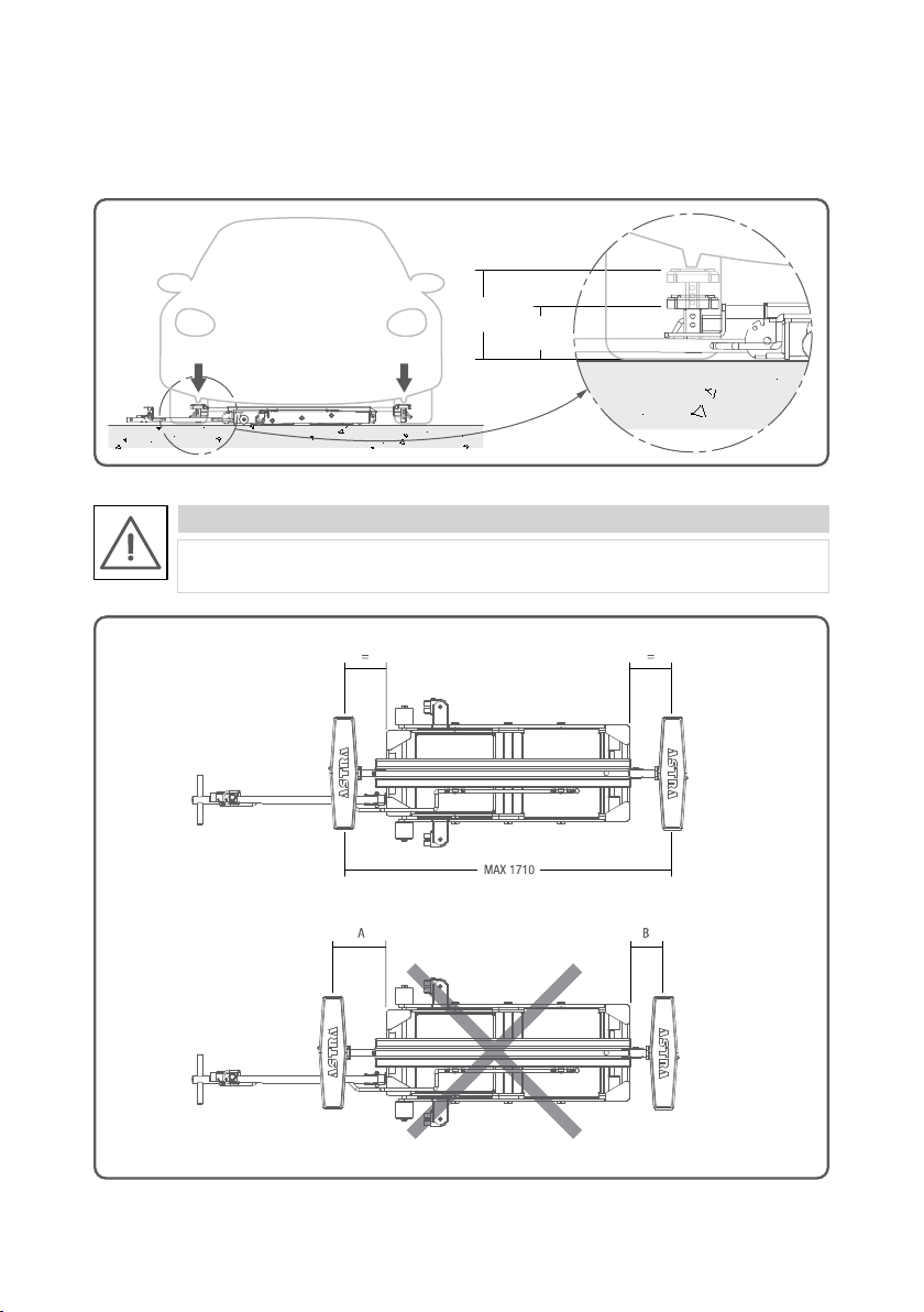
where is able to lift half of the vehicle up to 2.500kg.This lift is able to carry out three different movements:
·Front side elevation
·Rear side elevation
·Special side elevation
It means that, when you lift the car, front or rear wheels will be always raised.
The miniLIFT is an easy to use and versatile product. Thanks to its handle you can move the lift without
making effort to any place of the garage and, in addition, to control the elevation of the lift.
The pneumatic system is easy to connect (you only need an air intake).
1 Information about this manual
2 Intended use
1.1 Symbols of the manual
DANGER
CAUTION
NOTE
Possible risk of death, serious injury and / or material damage.
Possible risk of injury and / or material damage.
Recommendations for the correct use.
4USER MANUAL · AE1001 MINILIFT

1. Elevator
2. Handle
3. Wheels
4. Rubber pad
5. Basic pads
6. Lifting arms
7. Safety stands
8. Manual and pins
02
01
03 05 0604 07 08
3 Installation
3.1 Unpacking
DANGER
Incorrect transportation. Use always proper devices for this function (forklift, crane, etc) and
wear protective shoes.
All the parts that form the elevator are sent in a simple pallet (“Figure 01”).
MANIPULATION OF THE CONTENT
Figure 01
· Place the lift in horizontal position and fix the crane to the elevator with two belts at each end, to transport
the structure correctly.
· Make sure that the tapes are in good conditions and correctly placed.
· Place the lift in the area intended for use so that the wheels are in contact with the pavement.
5USER MANUAL · AE1001 MINILIFT

· Set the wheels as shown in the “Figure 02”.
· Set the handle as shown in the “Figure 03”.
Figure 02
3.2 Assembly
Figure 03
6
USER MANUAL · AE1001 MINILIFT

· Set the pneumatic quick connector (not supplied) as shown in the “Figure 04”.
3.3 Start up
3.4 First use
· Connect the compressed air funnel and check the air pressure (from 6 to 9 BAR).
· Check that there are no leaks in the pneumatic ducts, the actuating valve and/or the pneumatic actuators.
· For lifting, press the pneumatic valve lever as shown in the “Figure 05”.
· For descending, press the pneumatic valve lever as shown in the “Figure 06”.
CHECKING THE LIFT / DESCENT MANEUVER
Figure 04
Figure 05 Figure 06
7USER MANUAL · AE1001 MINILIFT

4 How it works
4.1 Installation of the pads
· Place the lifting arms into the gaps of the elevator as shown in “Figure 7”.
· Fix the basic pads in the adaptors as showb in the “Figure 8”.
In those vehicles where there are no “heel pads”, but you can find some other lifting points under the
chassis, you can use the following optional pads (not included in the basic package).
· If you got these optional pads, you should follow the “Figure 09”.
Figure 07
Figure 08
Figure 09
8USER MANUAL · AE1001 MINILIFT

4.2 Positioning of the elevator
· Drive the lift by the handle and position it under the vehicle according to the desired part to be lifted
(“Figure 10”). See sections 4.4, 4.5 and 4.6.
· Follow the steps specified in the “Figure 11” for placing the handle in horizontal position.
DANGER
Use always the lift in areas with no obstructions neither inclinations.
CAUTION
The elevator must remain perpendicular to the length of the car (“Figure 12”).
If the vehicle is new or it’s wet, you must clean the area where the pads work, to prevent
any possible slide.
Figure 12
Figure 10 Figure 11
9
USER MANUAL · AE1001 MINILIFT

4.3 Positioning of the basic pads
Place the basic pad behind the area of the lifting point (in the middle) as shown in the “Figure 13”.
DANGER
Place the basic supports at the same length from the platform and without exceeding the
maximum as shown in the “Figure 14”.
Figure 13
Figure 14
MIN
123mm
MAX
215mm
10USER MANUAL · AE1001 MINILIFT

01
02
UP
DOWN
01
02
UP
DOWN
4.4 Lifting/down maneuver (front side of the vehicle)
4.5 Lifting maneuver (rear side of the vehicle)
Place the lift next to the gravity point of the car, in the front/rear part of the vehicle, as it’s showed on the
“Figure 15” and press the relevant button (“Figure 16”).
Place the lift next to the gravity point of the car, in the front/rear part of the vehicle, as it’s shown in the
“Figure 17” and press the relevant button (“Figure 16”).
DANGER
DANGER
Never place the lift in the gravity point of the car.
Place the supplied safety stands once the vehicle has been raised.
Never place the lift in the gravity point of the car.
Place the supplied safety stands once the vehicle has been raised.
Figure 15 Figure 16
Figure 17 Figure 16
11
USER MANUAL · AE1001 MINILIFT

4.6 Special side lifting maneuver
Place the rubber pad in the hole designed for it as shown in “Figure 18”.
Place the lift under the vehicle. The rubber should be placed in the hole intended for it, in alignment with
the heel or tab of the vehicle as shown in “Figure 19”.
DANGER
The side lifting maneuver is only possible when the pad is placed correctly as in “Figure 18”.
Please, be extremely caution careful during this operation.
Figure 18
Figure 19
12
USER MANUAL · AE1001 MINILIFT

4.7 Installation of the safety stands
Place the safety stands as shown in the “Figure 21”, and descend the lift until the stands make contact
with the ground.
DANGER
DANGER
Safety stands do not allow the operator to work under the vehicle.
STOP the lifting maneuver before the car be supported directly by the lift as in “Figure 20”.
Figure 21
Figure 20
13
USER MANUAL · AE1001 MINILIFT

4.8 Installation and use of the 4x4 adaptors (optionals)
Place the 4x4 pads as shown in “Figure 22”. It can be combined with the basic pads and the other optional
pads:
Figure 23
Figure 22
DANGER
Place the basic supports at the same length from the platform and without exceeding the
maximum length as shown in the “Figure 23”.
14USER MANUAL · AE1001 MINILIFT

5.1 Maintenance plan
Before each use.
At 6 months.
At 12 months.
At 6 years.
· Check the operation of the controls.
· Visual inspection of damages and leaks.
· Cleaning (see point 5.2).
· Regular inspection (see point 5.7).
· Replacing the pneumatic ducts.
· Replacing the pneumatic actuators.
TYPE TASKSPERIOD
5.2 Cleaning
Remove the dirt with a wet rag and dry it later with another rag.
CAUTION
Do not use abrasive detergents or water jet directly on the lift.
5 Maintenance
15USER MANUAL · AE1001 MINILIFT

5.7 Regular inspection
6.2 Schematic Pneumatic Circuit
The lift must be inspected by a specialist at least once every 12 months.
Here are the inspection points:
Mechanic system
Pneumatic system
· Review of all the points of union between scissors (seeger and bolts).
· Tighten all existing nuts.
· Check the welds for cracks or deformations.
· Check the readability of the adhesives.
· Review of all pneumatic ducts in search of leaks, cracks, deformations or any deterioration
symbol.
NOTE
We recommend you to keep an exhaustive control of elevator inspections in the “inspection
log” that you will find on page 24 of this manual.
6.1 Technical data
Maximum load admitted
Maximum height from the ground
Minimum height from the ground
Maximum width
Minimum length
Long maximum
Weight of the structure with accessories
Pneumatic circuit pressure
Ascent time
Descent time
2500 Kg
550 mm
130 mm
626 mm
1382 mm
2060 mm
152 Kg
6 a 8 BAR
13 seconds
17 seconds
6 Technical description
Figure 24
16USER MANUAL · AE1001 MINILIFT

6.3 Exploded view
Figure 25
INDEX
Top (Page 18)
Pneumatic system (Page 19)
Scissors (Page 20)
17USER MANUAL · AE1001 MINILIFT

Figure 26
01
05
02
03
04
06
07
08
09
10
11
12
13
14
15
16
17
18
19
20
21
22
23
18USER MANUAL · AE1001 MINILIFT

Figure 27
28
27
29
31
30
30
29
24
25
26
19USER MANUAL · AE1001 MINILIFT

Figure 28
32
33
34
35
36
37
38
39
40
41
42
43
44
45
46
47
48
49
50
51
20USER MANUAL · AE1001 MINILIFT
Table of contents