Snorkel S3219E User manual


Table of Contents
S3219E/S3220E/S3226E/S4726E/S4732E – 1500842 1
Table of Contents
Table of Contents
EC Declaration of Conformity .....................................2
Safety Rules ...............................................................3
Fall Restraint Lanyard Anchor Points .........................4
Introduction .................................................................5
............................................5
Special Limitations......................................................6
Platform Capacity ....................................................6
Manual Force ..........................................................6
Drive/Lift Pothole Protector Interlock .......................6
Drive/Lift Level Sensor Interlock .............................6
Lowering Alarm .......................................................6
Lowering Interrupt ...................................................6
Overload Protection ................................................6
Beaufort Scale .........................................................7
Controls and Indicators...............................................8
Battery Disconnect Switch ..........................................9
Lower Controls ...........................................................9
Emergency Stop Button ..........................................9
Control Selector/Ground Operation Switch .............9
Platform Raise/Lower Switch ..................................9
Upper Controls ...........................................................9
Emergency Stop Button ........................................10
Drive/Lift Selector Switch ......................................10
Joystick .................................................................10
Interlock Switch .....................................................10
Steer Switch ..........................................................10
Drive Range Switch
S3226E/S3220E/S4726E/S4736E .....................10
Horn Button ...........................................................10
Battery Condition Indicator ....................................10
Pre-Operation Safety Inspection ..............................10
System Function Inspection ..................................... 11
Operation ..................................................................12
Preparing for Operation ............................................12
Lower Controls .........................................................12
Upper Controls .........................................................12
Platform ....................................................................12
Raising and Lowering ............................................13
Lowering Interrupt .................................................13
Overload Protection ..............................................13
Extending ..............................................................13
Driving and Steering .................................................13
Drive Range Switch
S3226E/S3220E/S4726E/S4736E .....................14
Drive Speeds ........................................................14
Drive/Lift Level Sensor Interlock ...........................14
Fold Down Guardrails ...............................................14
Swing-Out Trays .......................................................15
Emergency Lowering ................................................15
Transporting the Machine .........................................16
Preparing for Transportation .................................16
Transporting ..........................................................16
Lifting With a Forklift ..............................................16
Winching ...............................................................16
Driving ...................................................................17
Hoisting .................................................................17
Storage .....................................................................17
Maintenance .............................................................18
Hydraulic Fluid ......................................................18
Check Hydraulic Fluid ...........................................18
Battery Maintenance .............................................18
Battery Charging ...................................................18
Inspection and Maintenance Schedule.....................19
Daily Preventative Maintenance Checklist ...............20
Preventative Maintenance Report .........................20
...........................................21
...........................................22
...........................................23
...........................................24
...........................................25

2 S3219E/S3220E/S3226E/S4726E/S4732E – 1500842
EC Declaration of Conformity of Machinery 2006/42/EC
EC-Konformitätserklärung für Maschinen 2006/42/EC
Declaration De Conformite CE pour les Machines 2006/42/EC
Declaracion De Conformidad CE Para Maquinaria 2006/42/EC
Dichiarazione Di Conformità CE Per Le Macchine 2006/42/EC
CE Conformiteitsverklaring voor Machinerie 2006/42/EC
EU Deklaration Avseende Överensstammelse För Maskinutrustning
2006/42/EC
EF-Samsvarserklaering For Maskiner 2006/42/EC
EF-Overensstemmelseserklaering for Maskiner 2006/42/EC
EU Vaatimustenmukaisuusvakuutus 2006/42/EC
Model Modello SXXXXE
Modell Verticaal model
Modele Malli
Modelo
Serial number Serienummer SXXXXE-04-XXXXXX
Matricola Numero de serie
Sarajanumero Matricola
Notified body Powered Access
Notifizierte Stelle Certification Ltd (PAC)
Organisme notifie Applethwaite Lodge, The Common
Organismo notificado Windermere
Aangemelde instantie Cumbria
Myndighet LA23 1JQ
Avendte harmoniserte standarder United Kingdom
Udpeget organ Notified body number 0545
Asiasta on tehty ilmoitus seuraaville tahoille
Ente Notificatore
EC Type Examination Certificate number
EC-Typenprufung Zertifikat-Nr
Examen type CE Numero de Certificat
Inspeccion tipo CE Numero de certificado
Attestato di certificazione CE nr
Onderzoek van het type EC Certificaatnummer
EU typkontroll Certifieringsnummer
EF-typeproving Sertifikatnummer
EF-typegodkendelse Nummer pa typeattest
EU-tyyppitarkastuksen nr.
Signed for Snorkel
Manufacturing Quality Manager Date
Gary Bradbury
Powered Access
Vigo Centre
Washington
Tyne and Wear
NE38 9DA
England
Manufacturer Snorkel,
Hersteller Fabrikant Vigo Centre, Washington,
Fabricant Tillverkare Tyne and Wear, England
Fabricante Produsent Tel: +44 (0) 845 1557 755
Fabbricante Valmistaja Fax: +44 (0) 845 1557 756
Authorized Representative
Autorisierte Vertretung
Representant autorise
Representante autorizado
Mandatario
Erkend vertegenwoordiger
Auktoriserad representant
Autorisert representant
Represenentant
Valtuutettu edustaja
Description Aerial Work Platform
Bezeichnung Arbeitsbühne
Description Plate-forme elevatrice de personnel
Descripcion Platforma aerea de trabajo con motor
Descrizione Piattaforma di sollevamento motorizzata
Beschrijving Mechanisch aangedreven werkplatform
Beskrivning Höj-och sänkbar arbetsplattform
Beskrivelse Selvgående arbetsplattform
Beskrivelse Motordrevet lofteplatform
Kuvaus Konevoimalla toimiva nostolava
Selvgående personarbetslift

S3219E/S3220E/S3226E/S4726E/S4732E – 1500842 3
Warning
All personnel shall carefully read, understand and follow all safety rules and operating instructions
before operating or performing maintenance on any Snorkel aerial work platform.
Electrocution Hazard Tip Over Hazard Collision Hazard Fall Hazard
THIS MACHINE IS
NOT INSULATED!
NEVER elevate the platform
or drive the machine while
elevated unless the machine
is on a firm, level surface.
NEVER position the platform
without first checking for
overhead obstructions or
other hazards.
NEVER climb, stand, or sit
on platform guardrails or
midrail.
USE OF THE AERIAL WORK PLATFORM: This aerial work platform is intended to lift persons, their tools and materials
used for the job. It is designed for repair, assembly, stockpicking jobs, etc., and assignments at workplaces above head height
(ceilings, cranes, roof structures, buildings, shelving, etc.). All other uses of the aerial work platform are prohibited and the
rules below must be adhered to!
THIS AERIAL WORK PLATFORM IS NOT INSULATED! Refer to applicable national standards for safe approach distances.
is prohibited! See “Platform Capacity” on page 6 for details.
The use and operation of the aerial work platform as a lifting tool or a crane is prohibited!
NEVER exceed the manual force allowed for this machine. See “Manual Force” on page 6 for details.
DISTRIBUTE all platform loads evenly on the platform.
NEVER
or debris; and avoiding them.
OPERATE machine only on surfaces capable of supporting wheel loads.
NEVER operate the machine when wind speeds exceed this machine’s wind rating. See “Beaufort Scale” on page 7 for details.
Do not operate the aerial platform in windy or gusty conditions. Do not add anything to or take anything into the aerial platform
that will increase the wind loading such as billboards, banners, flags, etc.
IN CASE OF EMERGENCY push EMERGENCY STOP switch to deactivate all powered functions.
IF ALARM SOUNDS
Climbing up the railing of the platform, standing on or stepping from the platform onto buildings, steel or prefab concrete
structures, etc., is prohibited!
Dismantling the entry gate or other railing components is prohibited! Always make certain that the entry gate is closed!
It is prohibited to keep the entry gate in an open position when the platform is raised!
To extend the height or the range by placing of ladders, scaffolds or similar devices on the platform is prohibited!
NEVER perform service on machine while platform is elevated without blocking elevating assembly.
INSPECT the machine thoroughly for cracked welds, loose or missing hardware, hydraulic leaks, loose wire connections, and
damaged cables or hoses before using.
VERIFY that all labels are in place and legible before using.
NEVER use a machine that is damaged, not functioning properly, or has damaged or missing labels.
To bypass any safety equipment is prohibited and presents a danger for the persons on the aerial work platform and in its
working range.
NEVER
are prohibited or permissible only at the approval by Snorkel.
AFTER USE, secure the work platform from unauthorized use by turning the keyswitch off and removing key.
Certain inherent risks remain in the operation of this machine despite utilizing proper design practices and safeguarding.
Care must be taken to ensure that the machines meets the requirements of stability during use, transportation, assembly,
dismantling when out of service, testing, or foreseeable breakdowns.
In the event of an accident or breakdown see “Emergency Lowering” on page 15, do not operate the aerial platform if it is
platform back into service.
SAFETY RULES

4 S3219E/S3220E/S3226E/S4726E/S4732E – 1500842
Fall Restraint Lanyard Anchor Points
All fall restraint lanyard anchor points on Snorkel aerial work platforms have been tested with a force of 61.3 KN (3,650 lbs)
per person.
See below examples of anchor points used on Snorkel machines with their corresponding per person rating.
NOTE: There can be more anchor points in the platform than the maximum number of occupants allowed in the
platform. Refer to the machine specifications for the correct occupancy rating before use.
Type 1
Type 2
Type 3
Type 4
Top View Top View
Top View Top View
Front View
Front View
Anchor point Type 1 is rated for one lanyard
attachment per loop. Refer to machine “Specifica-
tions” and platform decals for maximum number of
platform occupants.
Two Lanyards
Attached
One Lanyard
Attached
Anchor point Type 2 is rated for two lanyard
attachments per loop. Refer to machine “Specifications”
and platform decals for maximum number of platform
occupants.
Two Lanyards
Attached
One Lanyard
Attached
Anchor point Type 3 is rated for one lanyard
attachment per loop. Refer to machine “Specifications”
and platform decals for maximum number of platform
occupants.
One Lanyard
Attached
One Lanyard
Attached
Anchor point Type 4 is rated for one lanyard
attachment per loop. Refer to machine “Specifications”
and platform decals for maximum number of platform
occupants.

Introduction
S3219E/S3220E/S3226E/S4726E/S4732E – 1500842 5
Introduction
This manual covers the S3219E, S3220E, S3226E,
S4726E, and S4732E Aerial Work Platforms.
This manual must be stored on the machine at all times.
Read, understand and follow all safety rules and operating
instructions before attempting to operate the machine.
When contacting Snorkel for service or parts information,
be sure to include the MODEL and SERIAL NUMBERS
from the equipment nameplate. Should the nameplate
be missing, the SERIAL NUMBER is also stamped on
the front of the chassis.
Scissors
Structure
Right Side
Platform
Guardrails
Left Side
Chassis
Upper
Controls
Entry
Doors
Platform Extension
Battery Tray
Drive and Steer
Wheels
Pothole
Protector Skid
Groundstrap
Tie-Down/Lifting
Lugs
Electrical
Power Outlet
Battery Tray
Hydraulic Tray
Pump/Reservoir/Fluid Filter
Control Valve Tray
Freewheeling Valve/Brake Release Valve
Hand Pump/Diagnostic Display
Entry
Step
Toeboards
Lower
Controls
Operator’s
Manual
Battery Charger
LED Charge Indicators
Tie-Down/Lifting Lugs
Rear
Front
Forklift
Pockets
Emergency Lowering
Lever – S3219E
Serial
Number
Power to Platform
Receptacle
Battery
Charger
Receptacle
Emergency Lowering
Handle – S3220E
S3226E, S4726E, S4732E

Special Limitations
6 S3219E/S3220E/S3226E/S4726E/S4732E – 1500842
Special Limitations
Travel with the platform raised is limited to creep speed
range. Elevating the platform is limited to firm, level
surfaces only.
Danger
The elevating function shall ONLY be used when the
work platform is level and on a firm surface.
The work platform is NOT intended to be driven over
uneven, rough, or soft terrain.
Platform Capacity
The maximum platform capacity for the aerial platform is
stated in the “Specifications” on pages 21-25.
Danger
DO NOT exceed the maximum platform capacity or
the platform occupancy limits for this machine.
Manual Force
Manual force is the force applied by the occupants to
objects such as walls or other structures outside the
work platform.
Refer to the platform capacity decal on the machine for
specific maximum allowable manual force information.
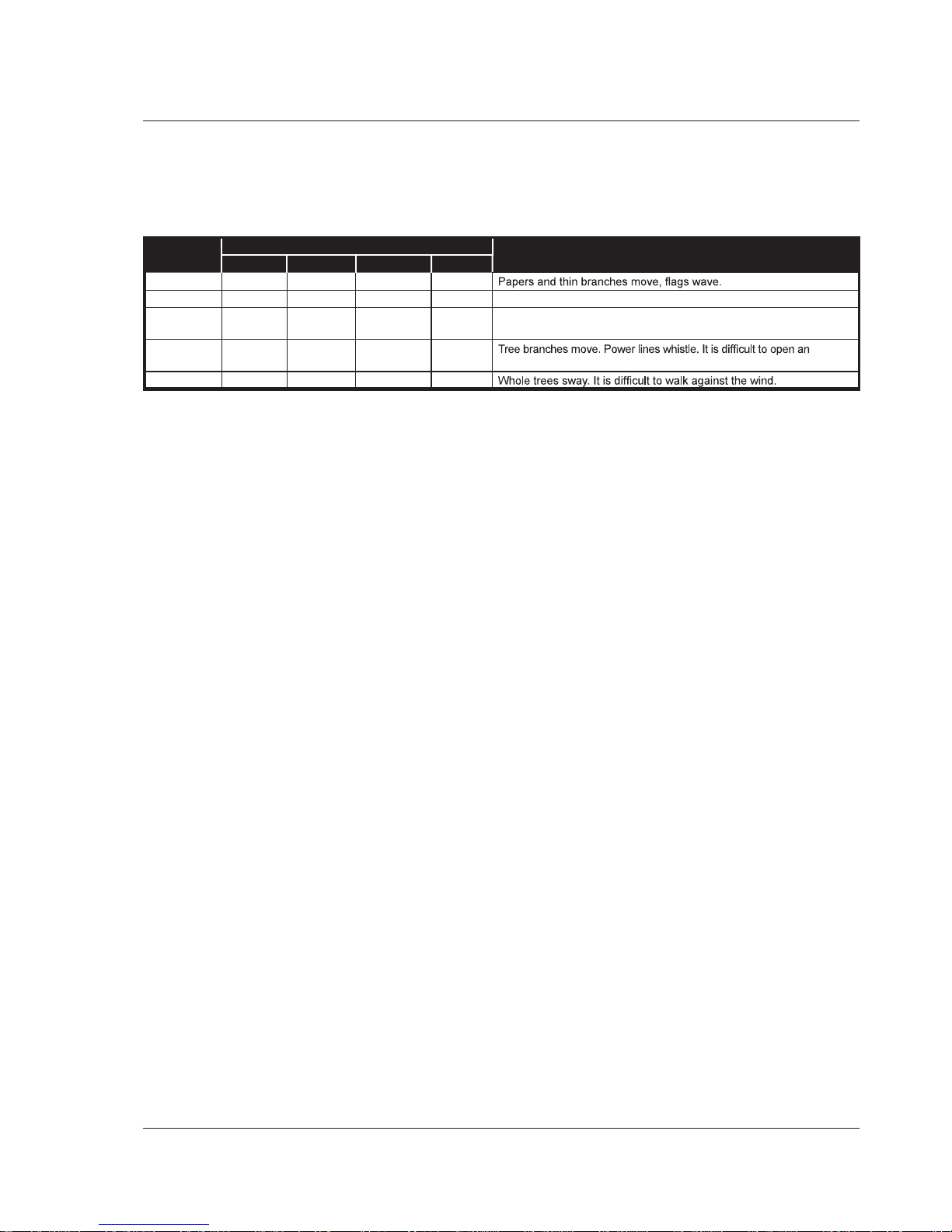
The maximum allowable manual force varies depending
on wind speed. The maximum allowable wind speed is
12.5 m/s (28 mph).
Danger
DO NOT exceed the maximum amount of manual
force for this machine.
Drive/Lift Pothole Protector Interlock
The aerial platform drive and lift functions are interlocked
through a limit switch inside the chassis that senses
whether or not the pothole protection linkage is locked
into position. The drive/lift pothole interlock operates when
the platform is elevated approximately 1.8 m (6 ).
If an obstruction under the skids, or some other impairment
prevents the skids from locking into position, the drive and
steer functions will not operate and an alarm will sound.
Lower the platform and remove the obstruction when the
drive/lift pothole protector interlock alarm sounds.
Drive/Lift Level Sensor Interlock
The aerial platform drive and lift functions are interlocked
through a level sensor system. The drive/lift level sensor
interlock operates when the platform is elevated approxi-
mately 1.8 m (6 ).
If the chassis is tilted too far out of level, the drive and
lift functions will not operate and an alarm will sound.
Refer to the machine specifications for the level sensor
factory setting.
Lower the platform and drive to a level surface when the
drive/lift level sensor alarm sounds.
The drive/lift level sensor system is for added protection
and does not justify operating on anything other than firm,
flat, level surfaces.
Lowering Alarm
When the joystick is moved out of neutral to lower the
platform, the alarm emits a loud beeping sound to warn
personnel in the work area to stand clear.
Danger
Pinch points exist on the scissors structure. Death
or serious injury will result if the scissors structure
lowers onto personnel within the scissors arms or
under the raised platform. Stand clear while raising
and lowering the platform.
Be careful when lowering the platform. Keep hands and
fingers away from the scissors structures components.
Lowering Interrupt
When the platform is lowered to about 1.8 m (6 ) lowering
stops. The platform will not lower for five seconds regard-
less of the control position to allow personnel to clear the
area of the scissors before the platform completely lowers.
Center the control in neutral to reset the lowering function,
then continue to lower the platform.
When the platform is below 1.8 m (6 ) and the control is
moved to lower the platform, there is a 1.5 second delay
before movement begins.
Overload Protection
When the load in the platform is near or at rated capac-
ity, an alarm will sound and the red light on the lower
The alarm and light warn the operator that the platform
is close to becoming overloaded. All functions remain
fully operational.
Danger
The aerial platform can tip over if it becomes unstable.
Death or serious injury will result from a tip-over ac-
cident. Do not exceed the capacity values indicated
on the platform rating placard.
If the platform is fully lowered and is overloaded, when
it is elevated just past 1.8 m (6 ), a control module will
stop the lift and drive functions and the alarm will sound
lowered to remove the excess load.
If the platform is elevated just past 1.8 m (6 ) and material
is added to the platform overloading it, a control module
will stop the lift, drive and lower functions and the alarm
remove the load in excess of rated capacity and cycle

Special Limitations
S3219E/S3220E/S3226E/S4726E/S4732E – 1500842 7
BEAUFORT
RATING
WIND SPEED GROUND CONDITIONS
m/s km/h ft/s mph
3 3,4~5,4 12,25~19,4 11.5~17.75 7.5~12.0
4 5,4~8,0 19,4~28,8 17.75~26.25 12.0~18 Dust is raised, paper whirls up, and small branches sway.
5 8,0~10,8 28,8~38,9 26.25~35.5 18~24.25 Shrubs with leaves start swaying. Wave crests are apparent in ponds
or swamps.
6 10,8~13,9 38,9~50,0 35.5~45.5 24.5~31 umbrella.
7 13,9~17,2 50,0~61,9 45.5~56.5 31.~38.5
Figure 1 – Beaufort Scale
the emergency stop button at the upper controls to return
to normal operation.
Beaufort Scale
Never operate the machine when wind speeds exceed
12.5 m/s (28 mph) [Beaufort scale 6]. Refer to Figure 1.

Controls and Indicators
8 S3219E/S3220E/S3226E/S4726E/S4732E – 1500842
Figure 3 – Upper Controls and Indicators
Danger
Pinch points may exist between moving components.
Death or serious injury will result from becoming
trapped between components, buildings, structures,
or other obstacles. Make sure all personnel stand
clear while operating the aerial platform.
Controls to position the platform are located on the
lower control panel on the chassis and on the upper
control panel in the platform.
Controls to drive the aerial platform are located on the
upper control panel only.
The diagnostic center LCD display is located in the hy-
draulic tray next to the fluid reservoir (refer to Figure 4).
Upper Controls – Top
Upper Controls – Front
13
7
8
910
12
11
Controls and Indicators
The operator shall know the location of each control and
indicator and have a thorough knowledge of the function
and operation of each before attempting to operate the
machine.
Figure 2 – Rear of Chassis
1. Battery disconnect switch
2. Control selector/ground operation switch
3. Platform overload protection light
4. Platform raise/lower switch
5. Emergency stop button
6. Battery charger codes
7. Battery condition indicator
8. Interlock switch
9. Joystick
10. Steer switch
11. Drive range switch – S3220E/S3226E/S4726/S4732E
12. Drive/lift selector switch
13. Horn button
1
6
2
5
4
3
3
5

Controls and Indicators
S3219E/S3220E/S3226E/S4726E/S4732E – 1500842 9
Figure 4 – Diagnostic Center LCD Display
The LCD display shows the accumulated aerial platform
operating time and the available battery power to operate
the machine, when the battery disconnect and emergency
stop switch are in the on position.
Battery Disconnect Switch
The battery disconnect switch is located at the rear of the
chassis (refer to Figure 2).
The battery disconnect removes electrical power from all
electrically controlled functions when in the off position.
Place the switch in the on position to electrically con-
nect the battery to the electrical system.
Caution
Only authorized personnel should operate the aerial
platform. Unqualified personnel may cause injury
to coworkers or property damage. Lock the battery
disconnect switch in the off position before leaving
the aerial platform unattended.
Lock the battery disconnect switch in the off position
to prevent unauthorized use of the aerial platform.
Lower Controls
The lower controls (refer to Figure 2) are located at the
rear of the chassis. Only platform functions can be oper-
ated from the lower controls.
The following are located on the lower control panel:
Emergency stop button
Control selector/ground operation switch
Platform raise/lower switch
Platform overload protection light
Emergency Stop Button
The emergency stop is a two-position red push button.
Push the button inward to disconnect power to all
control circuits.
Twist the button to restore power.
Control Selector/Ground Operation Switch
Insert the key into the control selector/ground operation
switch.
In the upper position, aerial platform functions will not
operate from the lower or upper controls.
Turn the switch to the upper controls position to operate
the aerial platform functions from the upper controls.
Hold the switch downward continually in the lower con-
trols position to enable the platform raise/lower switch
functions. The switch is spring returned to the off position.
The upper controls will not operate while the control
selector is in the lower position.
Platform Raise/Lower Switch
The platform raise/lower switch is used to raise or lower
the platform. The switch is spring returned to the center
off position.
Hold the switch upward to raise the platform.
Hold the switch downward to lower the platform.
An alarm will sound as the platform lowers.
Upper Controls
The upper controls (refer to Figure 3) are located on the
control panel at the platform. Platform and drive functions
can be operated from the upper controls.
Warning
The potential for an accident increases from improp-
erly driving or steering the aerial platform. Death or
serious injury could result from such accidents. Make
sure the upper control panel is securely fastened in-
side the platform and facing the front of the machine.
Avoid driving the platform with the upper controls facing
the rear or side of the machine. In this position the ma-
chine is difficult to control because the drive and steer
control movements and their resulting machine move-
ments will not correspond.
Only operate the upper controls when the upper control
panel is securely fastened inside the platform and facing
the front of the machine.
The following are located on the upper control panel:
Emergency stop button
Drive/lift selector switch
Drive range switch – S3220E/S3226E/S4726/S4732E
Joystick to control platform lift, drive, and steer
Horn button
Battery condition indicator
Platform overload protection light

Pre-Operation Safety Inspection
10 S3219E/S3220E/S3226E/S4726E/S4732E – 1500842
Emergency Stop Button
The emergency stop (refer to Figure 3) is a two-position,
red push button on the front of the upper control panel.
Push the button inward to disconnect power from all
control circuits at the upper controls.
Twist the button to restore power.
Push the emergency stop button inward when the
upper controls are not in use to protect against unin-
tentional operation.
Note
The lower controls override the upper controls. If the up-
per control emergency stop is engaged the lower controls
can still be used to operate the aerial platform.
Drive/Lift Selector Switch
The drive/lift selector switch (refer to Figure 3) is used to
select either machine drive or lift functions. Both functions
can not be operated at the same time.
Place the drive/lift selector switch in the drive position
to drive the aerial platform using the joystick. The
platform will not raise or lower while driving.
Place the drive/lift selector switch in the lift position to
raise and lower the platform using the joystick.
Joystick
Use the joystick (refer to Figure 3) to operate the follow-
ing functions:
Aerial platform steering
Aerial platform drive and speed
Platform raise/lower and speed
Movement of the joystick in a given direction produces
a corresponding movement of the aerial platform. The
steering and drive functions may be operated separately
or simultaneously.
Interlock Switch
The joystick has an interlock switch in the handle (refer
to Figure 3).
Engage the interlock by grasping the joystick and
pulling the switch toward the handle.
Engage the interlock to activate the steering, drive,
or lift functions.
Steer Switch
The steer switch (refer to Figure 3) is a momentary con-
tact, rocker switch on top of the drive joystick. This switch
controls the two front wheels to steer the aerial platform.
To steer to the right, engage the interlock switch on
the joystick and hold down the right side of the steer
switch.
To steer to the left, engage the interlock switch on the
joystick and hold down the left side of the steer switch.
Note
The steering wheels are not self-centering. Set the steer-
ing wheels straight ahead after completing a turn.
Drive Range Switch
S3220E/S3226E/S4726E/S4732E
The drive range switch (refer to Figure 3) has two posi-
tions to select drive wheel operation:
High (Rabbit) – for normal driving conditions
Low (Turtle) – for driving on grades up to 25 percent
that require low speed and high torque operation,
Horn Button
The horn button (refer to Figure 3) is on the front of the
upper control panel.
Press the button to sound the horn.
Battery Condition Indicator
The battery condition indicator (refer to Figure 3) is lo-
cated on the top of the upper control panel. When the
light comes on, the lift function is cut out and drive speed
is reduced to slow.
Pre-Operation Safety Inspection
Note
Carefully read, understand and follow all safety rules,
operating instructions, labels and National Safety Instruc-
tions/Requirements. Perform the following steps each
day before use.
1. Open the trays and inspect for damage, fluid leaks
or missing parts.
2. Check the level of the hydraulic fluid with the platform
fully lowered. The fluid level must be between the full
and add marks. Add recommended hydraulic fluid if
necessary. See “Specifications” on pages 21-25.
3. Check that the fluid level in the batteries is correct.
See “Battery Maintenance” on page 18.
4. Verify that the batteries are charged.
5. Check that the AC extension cord has been discon-
nected from the outlet on the side of the chassis.
6. Check that all guardrails are in place and all fasteners
are properly tightened.
7. Inspect the machine thoroughly for cracked welds
and structural damage, loose or missing hardware,
hydraulic leaks, damaged control cable and loose
wire connections.

System Function Inspection
S3219E/S3220E/S3226E/S4726E/S4732E – 1500842 11
System Function Inspection
Refer to “Controls and Indicators” on page 8 for the loca-
tions of various controls and indicators.
Warning
STAND CLEAR of the work platform while performing
the following checks.
Before operating the machine, survey the work area
for surface hazards such as holes, drop-offs, bumps
and debris.
Check in ALL directions, including above the work
platform, for obstructions and electrical conductors.
1. Move the machine, if necessary, to an unobstructed
area to allow for full elevation.
2. Twist the Lower Control Emergency Stop Switch to
the ON position.
3. Twist the Upper Control Emergency Stop Switch to
the ON position.
4. Visually inspect the elevating assembly, lift cylinder,
and hoses for cracked welds and structural damage,
loose hardware, hydraulic leaks, loose wire connec-
tions, and erratic operation. Check for missing or
loose parts.
5. Hold the ground operation switch downward. Test
each machine function from the lower control station
(refer to Figure 2).
6. Test the emergency lowering system for proper op-
eration.
7. Push the Lower Control Emergency Stop Button to
check for proper operation. All machine functions
should be disabled. Twist the Lower Control Emer-
gency Stop Button outward to resume.
8. Enter the platform and close the gate.
9. Check that the route is clear of obstacles (persons,
obstructions, debris), is level, and is capable of sup-
porting the wheel loads.
10. Test each machine function from the upper control
station by engaging the interlock and operating the
function controls (refer to Figure 3).
11. Push the Upper Control Emergency Stop Button to
check for proper operation. All machine functions
should be disabled. Twist the Upper Control Emer-
gency Stop Button to resume.

Operation
12 S3219E/S3220E/S3226E/S4726E/S4732E – 1500842
Operation
The aerial platform may be operated from either the lower
or upper controls.
Danger
The aerial platform is not electrically insulated. Death
or serious injury will result from contact with, or inade-
quate clearance from, an energized conductor. Do not
go closer than the minimum safe approach distance
as defined by ANSI or national safety regulations.
Pinch points may exist between moving components.
Death or serious injury will result from becoming
trapped between components, buildings, structures,
or other obstacles. Make sure there is sufficient
clearance around the machine before moving the
chassis or platform. Allow sufficient room and time
to stop movement to avoid contact with structures
or other hazards.
The aerial platform can tip over if it becomes unstable.
Death or serious injury will result from a tip-over
accident. Operate the aerial platform on a firm, flat,
level surface. Avoid travel speeds and/or rough ter-
rain that could cause sudden changes in platform
position. Do not drive or position the aerial platform
for elevated use near any drop-off, hole, slope, soft
or uneven ground, or other tip-over hazard. Do not
operate the aerial platform in unapproved locations
or wind conditions.
The platform rated work load is the total weight of the per-
sonnel and equipment that may be lifted in the platform.
The work loads are stated on the platform rating placard
at the entrance to the platform.
Danger
The aerial platform can tip over if it becomes unstable.
Death or serious injury will result from a tip-over ac-
cident. Do not exceed the capacity values indicated
on the platform rating placard.
Capacity values indicate the rated lifting capacity and do
not indicate aerial platform stability.
The operator bears ultimate responsibility for ensuring
that the aerial platform is properly set up for the particular
conditions encountered.
Preparing for Operation
Use the following procedure to prepare the aerial platform
for operation:
1. Perform a pre-operation safety and system function
inspection.
2. Close and latch the control valve, hydraulic, and bat-
tery trays.
3.
Place the battery disconnect switch in the on position
.
Lower Controls
Only the platform raise and lower functions may be oper-
ated from the lower controls. The lower controls may be
used for initial set up of the aerial platform, and for testing
and inspection.
Use the following procedure to raise or lower the platform
using the lower controls.
1. Twist the emergency stop button (refer to Figure 2).
2. Insert the key into the control selector/ground opera-
tion switch and turn the switch to the lower controls
position. Hold the switch in the lower controls position.
3. Hold the platform raise/lower toggle switch up to raise
the platform and down to lower it.
4. Release the toggle switch to stop movement.
Upper Controls
The upper controls may be used for driving and position-
ing the aerial platform while on the job.
Before operating the upper controls, properly set up the
aerial platform as described under Preparing for Opera-
tion.
Use the following procedure to operate the aerial platform
from the upper controls:
1. From the lower controls, twist the emergency stop
button to restore power (refer to Figure 2).
2. Insert the key into the control selector switch and turn
the switch to the upper controls position.
Note
The upper controls will not operate while the control
selector is in the lower position.
3. Enter the platform and secure the gate.
4. From the upper controls, twist the emergency stop
button to restore power (refer to Figure 3).
5. The aerial platform may be driven and the platform
may be raised and lowered from the upper controls.
Platform
Use care when entering and exiting the platform to avoid
slipping and/or falling. Securely close the safety gate
when the platform is occupied.
Danger
The potential for an accident increases when the fold
down rails are lowered. Death or serious injury can
result in such accidents. Do not elevate the platform
with the fold down rails lowered. Use extreme care
when moving the aerial platform while the fold down
rails are lowered.

Operation
S3219E/S3220E/S3226E/S4726E/S4732E – 1500842 13
Be sure the fold down guardrails are up and the hardware
is securely tightened, anytime the machine is not being
transported.
Raising and Lowering
The raise speed is proportional to the joystick position.
The farther the joystick is moved, the faster the platform
raises. There is only one lowering speed.
1. Place the drive/lift selector switch (refer to Figure 3)
in the lift position.
2. Squeeze and hold the interlock switch against the
joystick.
To raise the platform, slowly pull the joystick
backward, until the desired height is reached.
To lower the platform, push the joystick forward.
Lowering Interrupt
When the platform is lowered to about 1.8 m (6 ) lowering
stops. The platform will not lower for five seconds regard-
less of the joystick position.
Center the control in neutral to reset the lowering function,
then continue to lower the platform.
When the platform is below 1.8 m (6 ) and the control is
moved to lower the platform, there is a 1.5 second delay
before movement begins.
Overload Protection
When the load in the platform is near or at rated capac-
ity, an alarm will sound and the red light on the upper
controls will flash.
The alarm and light warn the operator that the platform
is close to becoming overloaded. All functions remain
fully operational.
Danger
The aerial platform can tip over if it becomes unstable.
Death or serious injury will result from a tip-over ac-
cident. Do not exceed the capacity values indicated
on the platform rating placard.
If the platform is fully lowered and is overloaded, when
it is elevated just past 1.8 m (6 ), a control module will
stop the lift and drive functions and the alarm will sound
and the warning light will flash. The platform can still be
lowered to remove the excess load.
If the platform is elevated just past 1.8 m (6 ) and material
is added to the platform overloading it, a control module
will stop the lift, drive and lower functions and the alarm
will sound and the warning light will flash. In this case,
remove the load in excess of rated capacity and cycle
the emergency stop button at the upper controls to return
to normal operation.
Extending
The platform can be extended and securely locked into
position.
Use the following procedure to extend the platform:
1. Enter the platform and close the gate.
Caution
The extension deck is free to move when the exten-
sion handle locks are disengaged. Personal injury may
result from accidentally extending or retracting the
deck. Make certain both extension handle locks are
fully engaged when the deck is extended in the work-
ing position and when it is stowed. Do not attempt to
extend or retract the platform unless the aerial platform
is on a level surface.
2. While facing the front of the platform, grasp the
platform extension handles, raise them and push
the extension deck forward to extend the deck. Fully
lower the handles at the mid or front position and
ensure they are locked in their lowered position.
3. Try to move the rails back and forth to make sure the
platform extension deck is locked in position.
Use the following procedure to retract the platform:
1. Enter the platform and close the gate.
Caution
The extension deck is free to move when the exten-
sion handle locks are disengaged. Personal injury may
result from accidentally extending or retracting the
deck. Make certain both extension handle locks are
fully engaged when the deck is extended in the work-
ing position and when it is stowed. Do not attempt to
extend or retract the platform unless the aerial platform
is on a level surface.
2. While facing the front of the platform, grasp the
platform extension handles, raise them and pull the
extension deck backward to retract the deck. Fully
lower the handles at the stowed position and ensure
they are locked in the lowered position.
3. Try to move the rails back and forth to make sure the
platform extension deck is locked in position.
Driving and Steering
Danger
The aerial platform can tip over if it becomes unstable.
Death or serious injury will result from a tip-over ac-
cident. Do not drive an elevated aerial platform on
soft, uneven, or sloping surfaces. Do not drive on
grades that exceed 25 percent.

Operation
14 S3219E/S3220E/S3226E/S4726E/S4732E – 1500842
A fully stowed machine may be operated on grades up
to 25 percent. A grade of 25 percent is a 0.76 m (30 )
vertical rise in 3.05 m (10 ) horizontal length.
Warning
Death or serious injury could result from improperly
driving or steering the aerial platform. Read and un-
derstand the information in this manual and on the
placards and decals on the machine before operating
the aerial platform on the job.
Use the following procedure to operate the drive and
steer functions.
1. Place the drive/lift selector switch (refer to Figure 3)
in the drive position.
2. Push the drive joystick forward to move the chassis
forward. Pull the joystick backward to move the chas-
sis backward. The drive speed is proportional to the
joystick position.
3. To stop drive motion, return the joystick to neutral.
Note
To make an emergency stop push the emergency stop
button inward to apply the parking brakes.
4. The steer switch is a momentary contact, rocker
switch on top of the drive joystick. This switch controls
the two front wheels to steer the aerial platform.
To steer to the right, hold down the right side of
the steer switch.
To steer to the left, hold down the left side of the
steer switch.
Note
Holding the steer switch down too long may result in
a sharp turn. This is especially true when driving and
steering at the same time. It may be easier to turn the
wheels in small increments using a series of quick taps
on the steer switch.
5. Set the steer wheels straight ahead after completing
a turn. The steering wheels are not self-centering.
Drive Range Switch
S3220E/S3226E/S4726E/S4732E
The drive range switch has two positions to select drive
wheel operation:
High (Rabbit) – for normal driving conditions.
Low (Turtle) – for driving on grades up to 25 percent
that require low speed and high torque operation,
In high the machine will travel up to 3.2 km/h (2 mph) when
the platform is raised less than 2.4 m (8 ) and up to 0.6 km/h
(0.4 mph) when the platform is raised above 2.4 m (8 ). Place
the drive range switch in high for normal machine operation.
Caution
The extension deck is free to move when the exten-
sion handle locks are disengaged. Personal injury may
result from accidentally extending or retracting the
deck. Make certain both extension handle locks are
fully engaged when the deck is extended in the work-
ing position and when it is stowed. Do not attempt to
extend or retract the platform unless the aerial platform
is on a level surface.
Place the drive range switch in low, with the platform fully
lowered and the extension deck securely pinned, before
driving up a ramp to load the machine for transport.
Drive Speeds
The drive speed is proportional to the joystick position. The
farther the joystick is moved, the faster the travel speed.
Always slow down before traveling over rough terrain or
any sloped surface.
Drive speed ranges are interlocked through limit switches
that sense the platform position.
When the platform is elevated below approximately
1.8 m (6 ) the aerial platform may be driven with the
full range of drive speeds.
When the platform is elevated above 1.8 m (6 ) only
the slowest drive speed will work.
Warning
The potential for an accident increases when safety
devices do not function properly. Death or serious
injury could result from such accidents. Do not alter,
disable, or override any safety device.
Do not use the aerial platform if it drives faster than 0.6
km/h (0.4 mph), which is 5.3 m (7 7 ) in 30 seconds,
when elevated above 1.8 m (6 ).
Drive/Lift Level Sensor Interlock
drive functions are interlocked through a level sensor
system. If the chassis is tilted more than specified side-
to-side or front-to-rear (refer to “Specifications” on pages
21-25), platform raise and drive functions are disabled
and an alarm sounds when those controls are activated.
If the drive/lift level sensor interlock shuts off the platform
raise and drive functions, lower the platform and drive to
a level surface.
Fold Down Guardrails
The platform guardrails may be folded down to pass the
machine under low height obstructions.
This manual suits for next models
3
Table of contents
Other Snorkel Scissor Lift manuals
Popular Scissor Lift manuals by other brands

Niuli
Niuli Maxiton GTJZ Series Operation and maintenance manual

Kleton
Kleton MJ521 instruction manual

Linde
Linde CiTi One Series Original instructions

EASTMAN
EASTMAN ES1930 Operation & maintenance manual

Vestil
Vestil CART-500-LA Operation and maintenance manual

MAHA
MAHA TWIN F III 4.0 operating instructions

Beta
Beta 3910 Operation manual and instructions

U-Line
U-Line H-3767 manual

Mec
Mec 69 Series Operator's manual

Presto Lifts
Presto Lifts XP24-3 Series Installation, operation and service manual

Genie
Genie GS-2668 RT operators manual with maintenance information

DINGLI
DINGLI S06-EH operators manual with maintenance information