Astral Pool LumiPlus FLUIDRA CONNECT User manual

1
LUMIPLUS
MODBUS MANUAL V2
© Fluidra, S.A. 2013. All Rights Reserved.
All the trademarks are registered by Fluidra SA and/or its a iliates, or its respective owners. Fluidra
SA and its licensors will own all right, title and interest to the manual, technology and in ormation
including all portions, copies or modi ications thereo .
Every e ort has been made to ensure that the in ormation given is correct. However, due to
continuous product improvement, Fluidra reserves the right to make changes to products and
technical data without prior notice.

2
1.
INTRODUCTION TO MODBUS AND PRODUCT 4
1.1.
Principle o operation 4
1.2.
Basic Characteristics 4
2.
ELECTRICAL CONNECTIONS 5
3.
CABLE CHARACTERISTICS 5
4.
BUS ISOLATION AND TERMINATION RESISTORS 6
5.
PANEL INDICATOR 7
6.
MODBUS FUNCTIONS 7
6.1.
Functions supported 7
6.2.
Exception responses 8
7.
DEVICE DESCRIPTION AND CONFIGURATION 8
7.1.
General Description 8
7.2.
State Machine Diagram 9
7.3.
Address and baud rate selection 10
7.3.1.
Address setting 10
7.3.2.
Baud rate selecti n 10
7.4.
Broadcasting 11
7.5.
Watchdog 11
7.5.1.
Watchd g Triggering 11
7.5.2.
Watchd g SETUP 12
7.5.3.
Watchd g predefined C l r/Sequence 13
8.
OPERATION MODES 14
8.1.
Basic mode 14
8.1.1.
Start Predefined C l r/Sequence 14
8.1.2.
Checking current state 15
8.1.3.
Actuat r Change Request 16
8.1.4.
Request ON 16
8.1.5.
Request OFF 17
8.1.6.
Changing C l r 17
8.1.7.
Changing Sequence 19
8.1.8.
Changing Speed 20
8.1.9.
Sleep Time 21
8.1.10.
Checking LATCHED Alarms Register 21
8.1.11.
Checking instantane us err r Register 22
9.
BASIC MODBUS-RTU REGISTER MAP 23
1 . TROUBLESHOOTING GUIDE 28
11.
PRODUCT REVISION 28

3

4
1. INTRODUCTION TO MODBUS AND PRODUCT
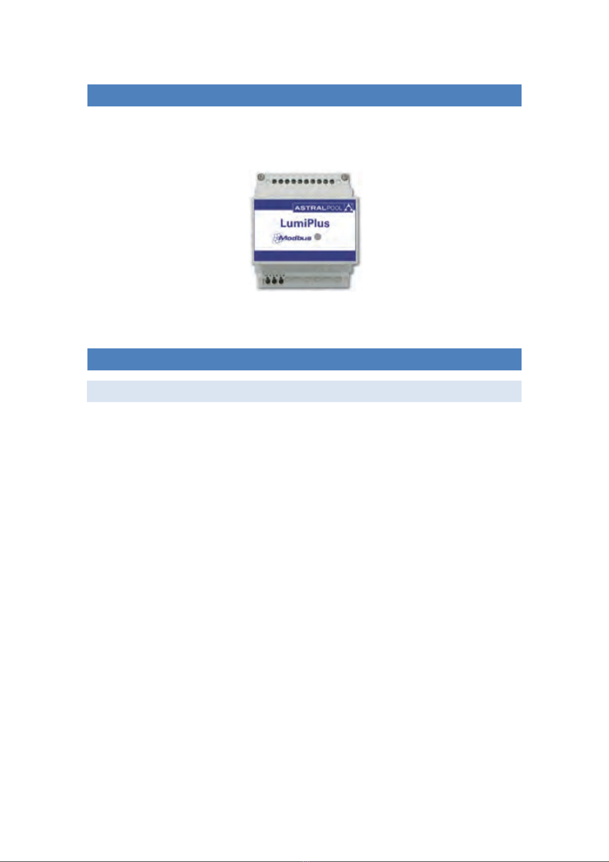
Thank y u very much f r purchasing ur Lumiplus with MODBUS-RTU features. This manual is
intended f r pr fessi nal installer, if y u are n t, please c nsult t y ur fficial distribut r.
MODBUS is an pen field bus successfully used thr ugh the w rld t c nnect field devices t a main
c ntr ller. This is the reas n why MODBUS has been ur ch ice t ffer t ur cust mers and
partners an aut mated s luti n easy t integrate n t nly with ur brand pr ducts but als with a
vast c llecti n f third party c mp nents and c ntr llers
MODBUS, MODBUS-RTU and ther related names are registered trademarks f MODBUS
Organizati n. Further inf rmati n and d cumentati n can be f und at http://www.M dbus. rg/
1.1. PRINCIPLE OF OPERATION
The Lumiplus implements MODBUS-RTU as a c ntr l-c mmunicati ns feature that all ws its
perati n and supervisi n tasks fr m a MODBUS aut mati n envir nment. Preventive maintenance
and fault analysis is als p ssible thanks t the implementati n f internal registers in the Lumiplus
with the m re relevant perati nal and err r events.
Whenever the Lumiplus is installed, y u are n t f rced t c nnect it t a MODBUS system, as far as
y u d n t aim t c ntr l r supervise it externally. The Lumiplus can run in l cal m de, as
traditi nally d ne, with ut using the MODBUS layer.
H wever, we expect that the implementati n f MODBUS-RTU in the Lumiplus will pen t ur
advanced cust mers and partners a wide range f new pp rtunities and implementati n scenari s
thanks t the simplicity and flexibility f the MODBUS-RTU layer.
Using a MODBUS-RTU message, the Lumiplus can change t a specific c l r, sequence r vel city,
rep rt err rs, hist rical data and s n, giving t the user/installer a wide range f new features
based in the aut mati n f an already existing and pr ved Lumiplus.
1.2. BASIC CHARACTERISTICS
The MODBUS c mmunicati n system pr vides a Master/Slave implementati n am ng devices sharing
a physical c nnecti n. F r the Lumiplus, the physical c nnecti n is a RS485 half duplex serial layer,
which has been ch sen am ng ther pti ns due t its wide implementati n and r ughness.
F r the Lumiplus, a RS-485 half duplex wired c nnecti n has been implemented and the pr ject r is
designed t run in a single-master system. In this implementati n, Master and Slave figures has a
clear r le that is crucial t clear understand f r a pr per system implementati n.
Master Device: Device that c ntr ls the data exchange in the bus and, if necessary, implements c -
rdinati n tasks am ng different slaves (i.e. PLC Pr grammable L gic C ntr ller, SCADA, etc).
Slave Device: Devices c nnected t the bus that attends t the requests fr m the master, either
rep rting inf rmati n r executing tasks as per Master request.

5
2. ELECTRICAL CONNECTIONS
Image 1 Electrical Connection
N te: s me manufacturers assign f r the RS-485 p rt the “A” c nnecti n as a “+”, and “B” as a “-“,
while thers reverses this n menclature. The Lumiplus uses the “A” as “+”, and the “B” as “-”. Mind
this aspect when c nnecting t the bus devices c ming fr m different manufacturers.
3. CABLE CHARACTERISTICS
The rec mmended wiring f r a MODBUS-RTU C mmunicati n is based in a linear structure, active
bus with terminati n at b th ends. Is p ssible c upling and unc upling f devices during perati n
with ut affecting ther devices. The wire shall be twisted and shielded acc rding t EN 50 170.
The values f transmissi n rate supp rted f r the device, all w maximum cable length f 1,200 m
with ut repeaters, r up t 10 km using repeaters, when installati n is acc rding t the standard.
F r the balanced pairs used in an RS485-system, a Characteristic Impedance with a value higher than
100 Ohms may be preferred, especially f r 19200 and higher baud rates.

6
4. BUS ISOLATION AND TERMINATION RESISTORS
If the c mmunicati n bus is accessible f r the user, it shall be d uble insulated. As far as in general
the accessibility f the bus t users will depend n each single installati n, safety is lati n has been
implemented in the Lumiplus physical bus layer. M re ver, f r safety purp ses, it is rec mmended t
ensure that ther devices sharing this bus als implements this insulati n.
Additi nally, the use f bus insulated devices n t nly enhances the security level, furtherm re
increases the equipment reliability, larger immunity t electr magnetic interference, l nger life,
higher reliability, m re stability ver the range f temperatures.
Whenever single r multiple devices are c nnected sharing a bus physical c nnecti n, it is
rec mmended t use terminating resist rs at the ends f the bus, even m re when use large cable
length r high speed data rates. The terminating resist r is used t prevent an RF signal fr m being
reflected back fr m the end, causing interference. The terminating resist r must be in b th ends f
the bus, c nnected in parallel (as sh wn in the image bel w). A typical value f this resistance is
120Ω, 0.5W. The value f the resist r must be the same in b th ends. The terminating resist rs are
the resist rs ܴ
்
f the image bel w
Image 2 Terminating Resistors

7
5. PANEL INDICATOR
The Lumiplus m dule has a LED that is ON when the m dule is p wered. When data is transmitted
thr ugh M dbus, this LED blinks.
Image 3 Lumiplus Panel Indicator
6. MODBUS FUNCTIONS
6.1. FUNCTIONS SUPPORTED
Please, be care ul at the possible actuations, and make sure that the unction used is the correct.
BIT ACCESS MODE
Functi ns in bit access m de are implemented acc rding t the MODBUS-RTU standard described in
http://www.M dbus. rg/d cs/M dbus_Applicati n_Pr t c l_V1_1b.pdf
0x01 READ COILS
0x0F WRITE MULTIPLE COILS
0x05 WRITE SINGLE COIL. This function is not implemented in the Lumiplus. Since they can be work
rounded with the functions “Write Multiple Coils”, to the special case where the number of coils to be
written is one.
0x02 READ DISCRETE INPUTS.
REGISTER ACCESS MODE
Functi ns in register access m de are implemented acc rding t the MODBUS-RTU standard
described in http://www.M dbus. rg/d cs/M dbus_Applicati n_Pr t c l_V1_1b.pdf. In general
registers are unsigned 16 bit c ded.
0x03 READ HOLDING REGISTERS
0x04 READ INPUT REGISTERS
0x10 WRITE MULTIPLE REGISTERS

8
6.2. EXCEPTION RESPONSES
Excepti n resp nses are implemented acc rding t the MODBUS-RTU standard described in the
chapter MODBUS excepti n resp nses:
http://www.M dbus. rg/d cs/M dbus_Applicati n_Pr t c l_V1_1b.pdf
The excepti ns implemented are fr m 1 t 3.
7. DEVICE DESCRIPTION AND CONFIGURATION
7.1. GENERAL DESCRIPTION
If a request is made thr ugh M dbus and later an ther ne with the rem te c ntr l, the M dbus will
indicate the c l r set thr ugh M dbus, it is because the unidirecti nality between M dbus m dule
and the Lumiplus m dulat r c ntr lled tr ugh rem te c ntr l.
When a simultane us request is made thr ugh M dbus and rem te c ntr l, and there is n c nflict,
the last request will take effect.
In general, there is n t check n the c nstancy f the values sent t specific registers. Theref re is the
perat r resp nsibility t check that c nsistency.
In this manual, the numbers in hexadecimal have been represented with the f rmat 0xZZ, where ZZ is
the number.
The register map that g verns the7.2 State Machine Diagram and all that is explained bel w is in the
chapter 9 Basic M dbus-RTU register map.

9
7.2. STATE MACHINE DIAGRAM
When the sistem P wers ON, the state is always Start. The Start m de d es n t indicates a Light ON,
it nly idicates the alimentati n f the Lumiplus, and NO request has been made after alimentati n.
It is p ssible t change the Start Predefined C l r, Sequence and Speed, alls is p ssible t c nfigure
the Start m de with all the Lights OFF. Fr m Start is p ssible t g t Request C l r State tr ugh
requesting an Update Predefined C l r, is p ssible t g t Request Sequence & Speed State thr ugh
requesting an Update Sequence & Speed r g t the Watchd g State if it triggers.
Diagram 1 State Machine Diagram

10
7.3. ADDRESS AND BAUD RATE SELECTION
7.3.1. ADDRESS SETTING
The address f the Lumiplus in the bus is set thr ugh the 0x00 H lding Register.
ID_Address: Address f the Lumiplus in the bus.
Fact ry setting: 0x30.
Suggested range: 0x30 - 0x3F.
The fact ry default f r the Lumiplus is (0x30). H wever y u can change this value by sending writing
this h lding registers and as far as y u check t d n t intr duce c llisi ns r c nflicts with ther
slave’s addresses.
Example: changing the address ID fr m 0x30(default) t 0x31.
Transmit Message: 30 10 00 00 00 01 02 00 31 3E 15
Where:
30 is the slave address. (The actual ID address).
10 is the functi n used. Write Multiple Registers.
00 00 is the address f the H lding Register t be written.
00 01 is the number f H lding Registers t be written. 1 in this case.
02 is the number f bytes f data t be sent.
00 31 is the new ID address.
3E 15 is the CRC.
7.3.2. BAUD RATE SELECTION
The Baud Rate selecti n f the serial c mmunicati ns with the Lumiplus set thr ugh the 0x01 H lding
Register. By default, 9600 bps and 8E1 (8 data bits, Even Parity, 1 st p bit) is implemented. H wever,
19200 bps and 2 st p bits are als supp rted (when NO parity is implemented).
The reas n f r supp rting N2 frames is t keep the MODBUS standard requirement f sending eleven
bits per byte ( 1 start + 8 data + 1 parity + 1 st p). Whenever a N parity c nfigurati n is ch sen, then
2 st p bits are intr duced t keep the eleven bits per byte required by the standard.
F r c mpatibility reas ns, N1 frames are als supp rted. H wever, mind that using this selecti n y u
are n t fulfilling the MODBUS standard requirements as far as nly ten bits per byte are used.
Acc rding t this, the baud rate and frame selecti n is c mpleted defining the baud rate (in bauds),
number f data bits, parity and number f st p bits.

11
COM_Setup: C mmunicati n setup
Fact ry setting: 0 9600, 8E1
Supp rted values: 0 9600, 8E1
1 19200, 8E1
2 9600, 8N2
3 19200, 8N2
4 9600, 8N1
5 19200 8N1
7.4. BROADCASTING
Br adcasting is n t supp rted by the Lumiplus.
7.5. WATCHDOG
The watchd g is a feature implemented in the Lumiplus aimed t check if the c mmunicati ns in the
bus keep alive. This is meanly a safety feature intended t detect a fail in the c mmunicati ns, and
all ws changing t a predefined state.
The Watchd g is triggered when the device d es n t receive tw messages in less than watchd g
time specified.
Acc rding t these descripti ns, either the time c nsidered f r triggering the watchd g as well as h w
t pr ceed then, needs t be defined.
If the watchd g has been activated, any request thr ugh M dbus will n t be made. In this State, the
Lumiplus nly can be read, and will n t accept changes. The alarm f the watchd g in h lding register
0x20 will be at 1; nly setting this alarm t 0 thr ugh M dbus r switching OFF the p wer supply,
Lumiplus will all w changes r requests.
T all w c rrect err rs if a bad c nfigurati n f the watchd g has been d ne, the first 30 sec nds f
the P wer ON f Lumiplus, the watchd g will be st pped. This all ws the user t change the
watchd g time if a sh rt time has been c nfigured, r all ws t deactivate the watchd g.
7.5.1. WATCHDOG TRIGGERING
The watchd g triggering time is defined in the H lding Register 0x10. This time is set in sec nds. 0s
means watchd g is disables. This is the default value.
T enable the watchd g feature, set the watchd g time t a value different fr m 0. H wever, mind
the implicati ns f this value as l ng times may deal t useful setups.

12
Example: Set watchd g triggering time t 30s:
Transmit Message: 30 10 00 10 00 01 02 00 1E 7D 59
Where:
30 is the slave address.
10 is the functi n used. Write Multiple Registers.
00 10 is the address f the first H lding Register t be written.
00 01 is the number f H lding Registers t be written. 1 in this case.
02 is the number f bytes f data t be sent.
00 1E is the value t be sent. 30 in decimal.
7D 59 is the CRC.
N w, the watchd g time is set t 30s. Theref re, whenever tw pr perly c nstructed messages are
read in less than 30s, even n t addressed t the Lumiplus, the watchd g is n t triggered. Otherwise, it
is triggered.
T kn w the Watchd g time, is necessary read the h lding registers.
The resp nse f the Watchd g_time, in this case, will be: 30 03 02 00 1E 45 88
30 is the slave address.
03 is the functi n used. Read h lding registers.
02 is the number f bytes f data t be read.
00 1E is the time c nfigured. 30 in decimal.
45 88 is the CRC.
7.5.2. WATCHDOG SETUP
The Watchd g Setup, register 0x11, must be setup in c njuncti n with the Watchd g triggering
register, and the watchd g predefined c l r/sequence.
The High Byte f the register defines h w t pr ceed when the Watchd g is triggered. If it is set t 0,
then the Watchd g predefined c l r/sequence will be c nsidered. If it is set t 1, then the
c mmunicati n bridge is reset.
The Low Byte is n t c nsidered in this functi n. Set it t 0.
Example: C nfiguring the watchd g t d the defined in the watchd g predefined c l r/sequence:
Transmit Message: 30 10 00 11 00 01 02 00 00 FC 80
Where:
30 is the slave address.
10 is the functi n used. Write multiple registers.
00 11 is the address f the first register t be written.
00 01 is the number f registers t be written. 1 in this case
02 is the number f bytes t be sent.
00 High Byte. The watchd g will d the defined in the Watchd g predefined c l r/sequence.

13
00 L w Byte. Is n t c nsidered, 00 is a c rrect value.
FC 80 is the CRC.
7.5.2 Watchd g SETUP and 7.5.3 Watchd g predefined C l r/Sequence sh uld be c nfigured in
c njuncti n. See the example 7.5.3 Watchd g predefined C l r/Sequence, defining the C l r /
Sequence t be executed when watchd g triggers.
7.5.3. WATCHDOG PREDEFINED COLOR/SEQUENCE
The watchd g predefined c l r sequence, H lding Register 0x14, determines the c l r r the
sequence predefined when the watchd g triggers.
The High byte set the speed f the sequence, it can take values fr m 0 t 8. If it is set t 0, the speed
will be 0, which means that a c l r is fixed.
The Low Byte sets the color if the High Byte is 0, r the sequence if a different value f 0 is set in the
High Byte. The L w byte, can take values fr m 0 t 12, these are 12 p ssible c l rs r 8 p ssible
sequences, t be ch sen. If the L w Byte is set t 0 n c l r has been selected, which means that the
Lumiplus has n lights turned ON.
If the register is c nfigured like (0xFFFF), the luminaries remain with the c l r / sequence previ us f
the alarm state.
Example:
Set watchd g predefined c l r/sequence in case that watchd g is triggered, in this example the
Lumiplus will has all the lights turned OFF, and the Status when triggers will be Watchd g:
Transmit Message: 30 10 00 14 00 01 02 00 00 FC D5
Where:
30 is the slave address.
10 is the functi n used. Write multiple registers.
00 14 is the address f the first register t be written.
00 01 is the number f registers t be written.. 1 in this case.
02 is the number f bytes t be sent.
00 High Byte. is the speed, 0 is a fixed c l r.
00 L w Byte. C l r 0 ch sen. (C l r 0 nly exist in the watchd g predefined c l r/sequence,
and in the Start predefined c l r/sequence) there is n c l r, which means turn OFF the
lights.
F5 D5 is the CRC.
NOTE: Mind that watchd g functi n is implemented f r safety reas ns. H wever, the reas ns f r
activating it, r n t, depends n the installer/integrat r criteria. Always, mind f implicati ns n what
is being implemented. Use this feature under y ur resp nsibility.

14
8. OPERATION MODES
8.1. BASIC MODE
In this secti n it is assumed that a successful c nnecti n has been established with the Lumiplus and
theref re, address, baud settings and watchd g behavi r has been already set.
8.1.1. START PREDEFINED COLOR/SEQUENCE
The Start Predefined C l r/Sequence, is the c l r r sequence in which will w rk the Lumiplus when it
P wers ON.
The High byte set the speed f the sequence, it can take values fr m 0 t 8. if it is set t 0, the speed
will be 0 which means that a c l r is fixed.
The Low byte sets the color if the High byte is 0, r the sequence if a different value f 0 is set in the
High Byte. The L w byte can take values fr m 0 t 12, these are 12 c nfigured c l rs, r 8 sequences.
If it is set t 0, any light will be ON when the Lumiplus p wers ON.
If the register is c nfigured like (0xFFFF), the luminaries remain with the c l r / sequence previ us f
the last OFF.
The way t setting this parameter is the same that the Watchd g predefined c l r sequence, the nly
difference is the number f the h lding register, in this case the h lding register is 0x15.
In the Start Predefined C l r/Sequence and in the Watchd g predefined C l r/Sequence, is n t
necessary t make a request update t change the c l r, when the system Starts r, the watchd g
actuates.
Specific c l r requests and sequences are defined acc rding t the f ll wing c dificati n:

15
8.1.2. CHECKING CURRENT STATE
The state in which the Lumiplus is currently set is available thr ugh Status Input Register 0x00. This
register has a different meaning f r the L w byte and f r the High byte.
The less significant bit is used t sh w if an err r has ccurred and is set t 1 whenever an err r exist.
Detailed inf rmati n f the err r/err rs detected can be requested t the Alarms Input register at
0x01. Only the watchd g alarm has been implemented, which means that if an err r exist, surely is a
watchd g err r (watchd g has been triggered). Further t the raising f an err r the Lumiplus rep rt
an unrec verable err r that needs t p wer ff-p wer n t reset, r set the alarm t 0.
Until the alarms have been reset, the Lumiplus will n t accept any change, and nly will resp nse
inf rmati n (read nly).
The High Byte is used t sh w the current state f the Lumiplus.
The c des f r the different states implemented in the high byte are sh wn in the f ll wing table:
0x00 Start.
0x01 Watchd g.
0x02 Request C l r.
0x03 Request Sequence.
Mind the unidirecti nality described in chapter 7.1 General Descripti n.
C ding Examples (High byte first):
0x0002 2 Start State. ON, N err r.
0x0101 257 Watchd g State, Alarm. Light OFF. Reset needed. (This casuistic is p ssible
when the watchd g predefined c l r/sequence is c nfigured t turn OFF the lights).
0x0103 259 Watchd g State, Alarm. Light ON. Reset needed. (This casuistic is p ssible
when the watchd g predefined c l r/sequence is a c l r r sequence).
Example:
T kn w in which State is the Lumiplus, the transmit message must be:
30 04 00 00 00 01 35 EB
Where:
30 is the slave address.
04 is the functi n used. Read input registers.
00 00 is the address f the first input register t be read.
00 01 is the number f input registers t be read, 1 in this case.
35 EB is the CRC
The resp nse is 30 04 02 00 02 45 35, that indicates Start M de, with ut alarm, and light ON.
Where:

16
30 is the slave address.
04 is the functi n used. Read input registers.
02 is the number f bytes t be read.
00 is the high byte, it indicates that is in Start M de
02 is the l w byte, it indicates s me light is ON.
45 35 is the CRC.
In the example bel w, the time watchd g has been activated and the time with ut c mmunicati ns
has exceeded the watchd g time:
The resp nse is 30 04 02 01 01 04 A4, that indicates Watchd g State with watchd g alarm.
Where:
30 is the slave address.
04 is the functi n used. Read input registers.
02 is the number f bytes t be read.
01 is the high byte, it indicates that is in Watchd g state.
01 is the l w byte, it indicates that there is s me alarm.
04 A4 is the CRC.
8.1.3. ACTUATOR CHANGE REQUEST
Actuat r change request can be sent t the Lumiplus thr ugh the H lding Register 0x21. H wever,
these requests can als be sent using a bit address m de starting n c il bit 0x210. Mind that y u can
ch se either register address m de r bit address m de. H wever, f r clarificati n purp ses and t
av id misunderstandings, y u sh uld n t mix b th appr aches as far as y u d n t have a clear idea
n what are y u d ing.
8.1.4. REQUEST ON
T turn ON the lights f Lumiplus thr ugh MODBUS, the simplest way is setting t 1 the c il 0x210.
Example, bit address m de:
Transmitting message: 30 0F 02 10 00 01 01 01 ED AE
Where:
30 is the slave address.
0F is the functi n used. Write multiple c ils.
02 10 is the address f the first c il t be set.
00 01 is the number f c ils t be set, 1 in this case.
01 is the number f bytes f data t be sent.
01 is t set the request, and then turn ON the lights.
ED AE is the CRC.
Example, byte m de, H lding Register:

17
Transmitting message: 30 10 00 21 00 01 02 00 01 38 B0
Where:
30 is the slave address.
10 is the functi n used. Write multiple registers.
00 21 is the address f the first H lding Register t be set.
00 01 is the number f H lding Register t be set, 1 in this case.
02 is the number f bytes f data sent
00 01 is the data send.
38 B0 is the CRC
8.1.5. REQUEST OFF
T turn OFF the lights f Lumiplus thr ugh MODBUS, the simplest way is setting t 1 the c il 0x211.
Example:
Transmitting message 30 0F 02 11 00 01 01 01 D0 6E
Where:
30 is the slave address.
0F is the functi n used. Write multiple c ils.
02 11 is the address f the first c il t set.
00 01 is the number f c ils t be set, 1 in this case.
01 is the number f bytes f data sent.
01 is t set the request, and then turn OFF the lights.
D0 6E is the CRC.
Als , is p ssible t make a Request OFF by setting the H lding Register 0x21 t 0x02
8.1.6. CHANGING COLOR
T change the c l r f the Lumiplus thr ugh M dbus, is necessary t c mplete tw steps, these
steps, where n t necessary in the Watchd g and Start Predefined C l r/Sequence.
1. It is necessary to choose the prede ined color.
2. It is necessary to make a Request Update Prede ined Color.
Choosing the prede ined color:
The way t ch se the c l r is using the Requests H lding Register (0x25).
There is 12 predefined c l rs t ch se. Fr m 0x1 t 0xC (fr m 1 t 12) acc rding t the table ab ve.

18
Example:
Transmitting message 30 10 00 25 00 01 02 00 01 39 34
Where:
30 is the slave address.
10 is the functi n used. Write multiple registers.
00 25 is the address f the first H lding Register t be set.
00 01 is the number f H lding Register t be set, 1 in this case.
02 is the number f bytes f data sent
00 01 is the c l r send (Red)
39 34 is the CRC
Request Update Prede ined Color:
A way t request an Update Predefined C l r is using the bit-address m de n the Requests H lding
Register 0x21. The simplest way is setting t 1 the c il 0x213.
Transmitting message: 30 0F 02 13 00 01 01 01 A9 AE
Where:
30 is the slave address.
0F is the functi n used. Write multiple c ils.
02 13 is the address f the first C il t be set.
00 01 is the number f C ils t be set, 1 in this case.
01 is the number f bytes f data sent
01 is the request Update
A9 AE is the CRC
Als , is p ssible t make a Request Update predefined C l r by setting the H lding Register 0x21 t
0x08.

19
8.1.7. CHANGING SEQUENCE
T change the Sequence f the Lumiplus thr ugh M dbus, is necessary t c mplete tw steps.
1. It is necessary to choose the prede ined sequence.
2. It is necessary to make a Request Update Sequence & Speed.
Choosing the prede ined sequence:
The way t ch se the sequence is using the Requests H lding Register 0x26.
There is 8 predefined sequences t be ch sen. Fr m 0x1 t 0x8 (fr m 1 t 8).
Example: changing the sequence t 8.
Transmitting message 30 10 00 26 00 01 02 00 08 F9 01
Where:
30 is the slave address.
10 is the functi n used. Write multiple registers.
00 26 is the address f the first H lding Register t be set.
00 01 is the number f H lding Registers t be set, 1 in this case.
02 is the number f bytes f data t be sent.
00 08 is the sequence t be send (the sequence 8).
F9 01 is the CRC.
Request Update Prede ined Sequence & Speed:
A way t request an Update Predefined sequence & speed is using the bit-address m de n the
Requests H lding Register 0x21, setting t 1 the c il 0x214.
Transmitting message: 30 0F 02 14 00 01 01 01 1C 6E
Where:
30 is the slave address.
0F is the functi n used. Write multiple c ils.
02 14 is the address f the first C il t be set.
00 01 is the number f C ils t be set, 1 in this case.
01 is the number f bytes f data t be sent.
01 is the request Update.
1C 6E is the CRC.
Als , is p ssible t make a Request Update predefined Sequence & Speed by setting the H lding
Register 0x21 t 0x10.

20
8.1.8. CHANGING SPEED
T change the Speed f the Lumiplus thr ugh M dbus, is necessary t c mplete tw steps.
1. It is necessary to choose the prede ined speed.
2. It is necessary to make a Request Update Sequence & Speed.
Choosing the prede ined speed:
The way t ch se the sequence is using the Requests H lding Register (0x27).
There is 8 predefined speed t ch se. Fr m 0x1 t 0x8 (fr m 1 t 8).
Example: changing the speed t 8.
Transmitting message 30 10 00 27 00 01 02 00 08 F8 D0
Where:
30 is the slave address.
10 is the functi n used. Write multiple registers.
00 27 is the address f the first H lding Register t be set.
00 01 is the number f H lding Registers t be set, 1 in this case.
02 is the number f bytes f data sent.
00 08 is the speed send (speed 8).
F8 D0 is the CRC.
Request Update Prede ined Sequence & Speed:
A way t request an Update Predefined sequence & speed is using the bit-address m de n the
Requests H lding Register 0x21. The simplest way is setting t 1 the c il 0x214.
Transmitting message: 30 0F 02 14 00 01 01 01 1C 6E
Where:
30 is the slave address.
0F is the functi n used. Write multiple c ils.
02 14 is the address f the first C il t be set.
00 01 is the number f C ils t be set, 1 in this case.
01 is the number f bytes f data t be sent.
01 is the request Update.
1C 6E is the CRC.
Als , is p ssible t make a Request Update predefined Sequence & Speed by setting the H lding
Register 0x21 t 0x10.
This manual suits for next models
2
Table of contents